Figures
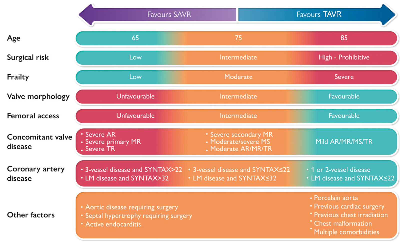
eFigure 15.3
TAVR and SAVR. This chart shows the decision-making process between TAVR and SAVR in patients with AS. The SYNTAX score is an angiographic grading tool to determine the complexity of coronary artery disease. Abbreviations: AR, aortic regurgitation; AS, aortic stenosis; LM, left main; MR, mitral regurgitation; MS, mitral stenosis; SAVR, surgical aortic valve replacement; TAVR, transcatheter aortic valve replacement; TR, tricuspid regurgitation. With permission from Windecker et al.11
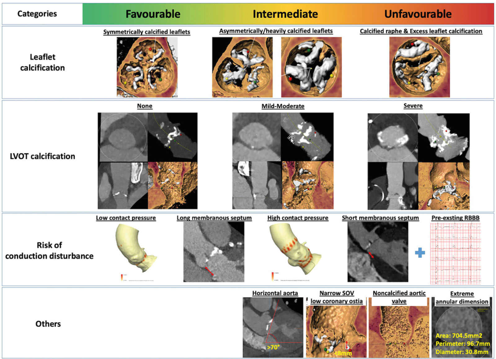
eFigure 15.4
TAVR suitability. This chart risk stratifies native AoV morphology into categories of favorable, intermediate, unfavorable to indicate the suitability for TAVR. Abbreviations: AoV, aortic valve; LVOT, left ventricular outflow tract; RBBB, right bundle branch block; SoV, sinus of Valsalva; TAVR, transcatheter aortic valve replacement. With permission from Windecker et al.11
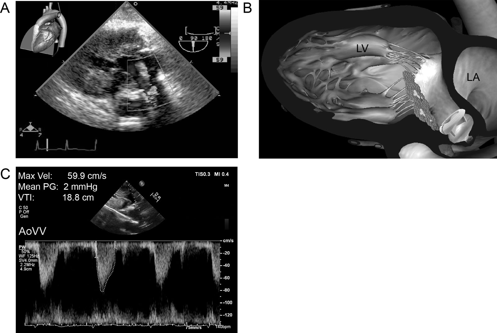
eFigure 15.11
Bioprosthetic transvalvular pressure gradient. (A,B) Deep modified TG view at 90° with CFI of a bioprosthetic AoV during systole shows turbulent flow through the valve. (C) The mean transvalvular PG is 2 mmHg using CWD. Abbreviations: AoV, aortic valve; AoVV, aortic valve velocity; CFI, color flow imaging; CWD, continuous wave Doppler; LA, left atrium; LV, left ventricle; Min, minimum; PG, pressure gradient; TG, transgastric; Vel, velocity; VTI, velocity–time integral.
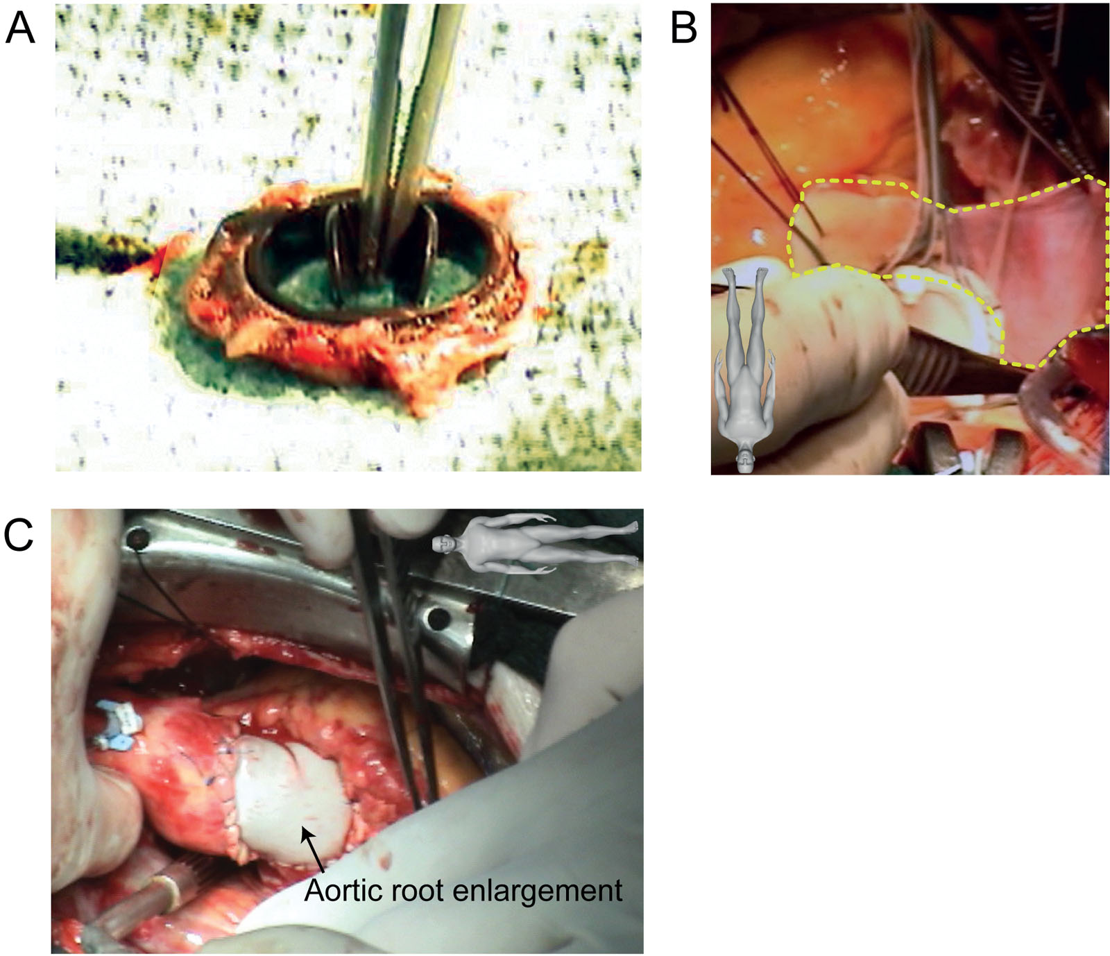
eFigure 15.13
AVR PPM. This is 71-year-old man with a body surface area of 1.89 m2 was re-operated on for symptoms of severe prosthetic valve stenosis associated with a Carbomedics 19 mm mechanical bileaflet prosthesis (effective orifice area = 1.06 cm2) implanted 4 years earlier. (A) The preoperative mean gradient was 41 mmHg, although intraoperative inspection of the explanted prosthetic valve was completely normal. (B,C) The surgeon performed an aortic root enlargement to accommodate a larger bioprosthetic valve. Abbreviations: AVR, aortic valve replacement; PPM, patient prosthetic mismatch. Source: Courtesy of Dr. Michel Carrier.
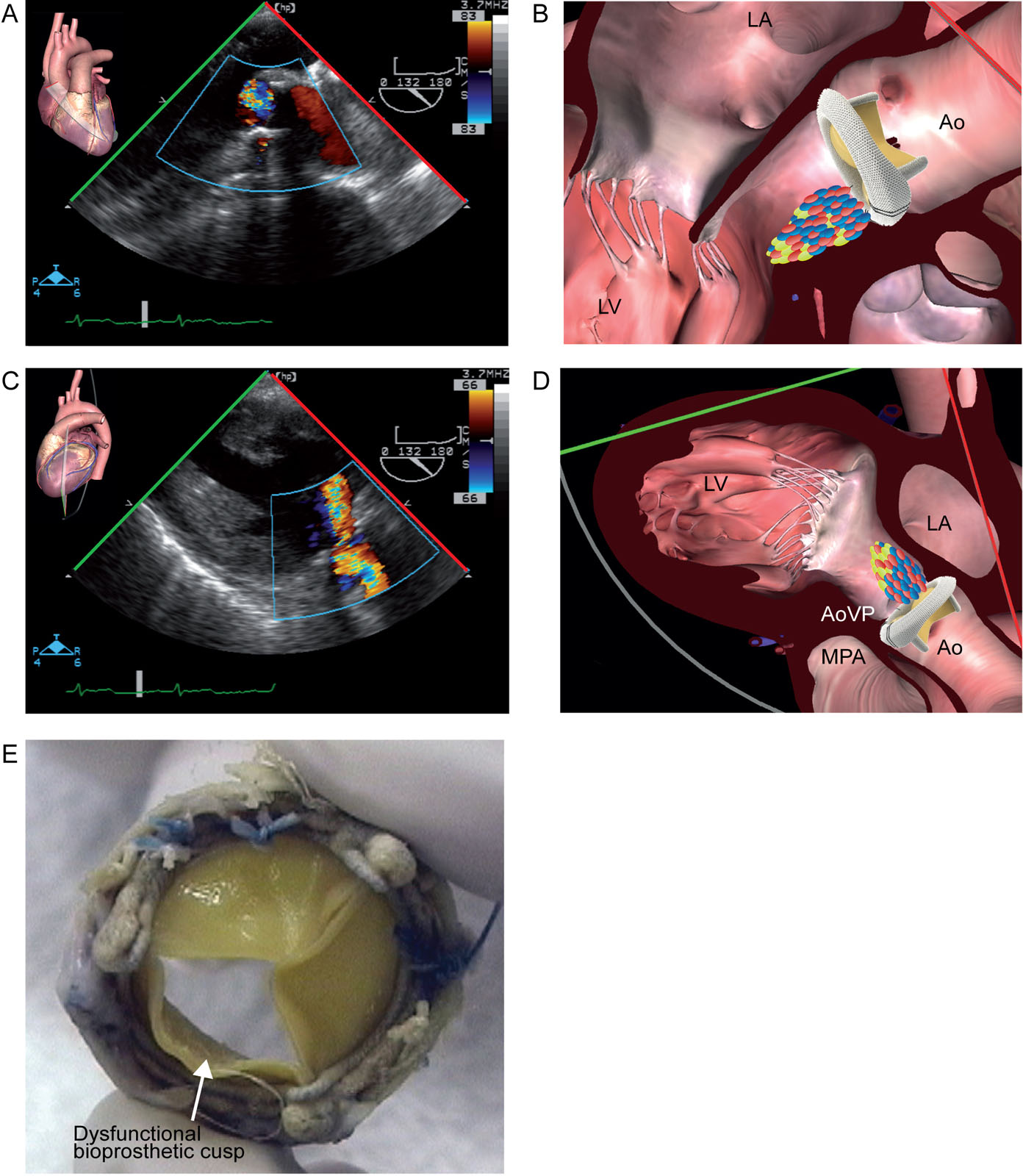
eFigure 15.14
Bioprosthetic AVR dysfunction. A 60-year-old man was reoperated for periprosthetic AR. (A–D) After the procedure, the ME LAX and TG LAX views with CFI show significant valvular AR. The new bioprosthesis was removed and replaced by another one. (E) Examination of the defective bioprosthesis showed abnormal motion of one of the leaflets. Abbreviations: Ao, aorta; AoVP, aortic valve prosthesis; AR, aortic regurgitation; AVR, aortic valve replacement; CFI, color flow imaging; LA, left atrium; LAX, long-axis; LV, left ventricle; ME, mid-esophageal; MPA, main pulmonary artery; TG, transgastric. Source: Photo E courtesy of Dr. Tack Ki Leung.
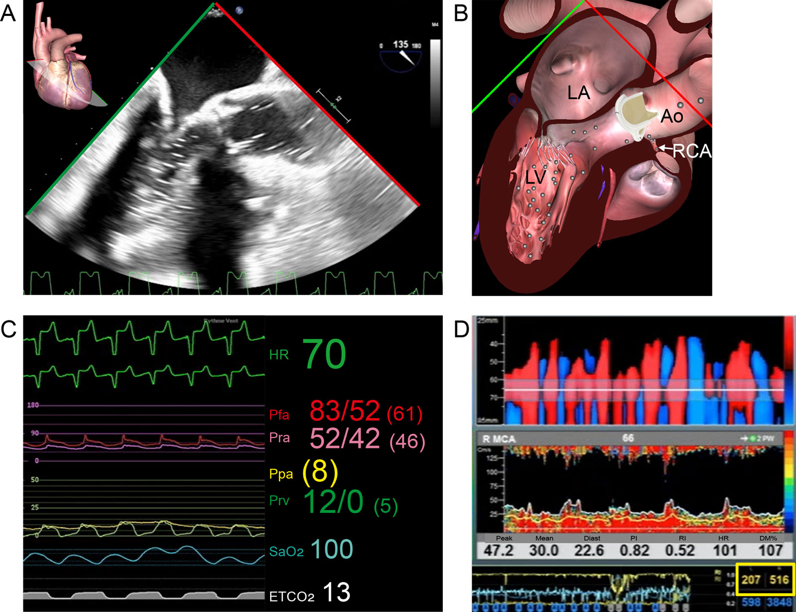
eFigure 15.15
Air embolism. This 61-year-old woman after surgical AVR experiences difficulty during weaning from CPB. (A,B) ME LAX view shows air in the LVOT and aortic root resulting air embolism in the RCA with RV dysfunction. (C) Hemodynamic parameters show ST changes on the ECG but also a significant difference between the Pfa and Pra. (D) Air emboli detection using TCD detected 207 and 516 high intensity transient signals on the right and left middle cerebral artery (MCA) (yellow box) respectively. Abbreviations: Ao, aorta; AVR, aortic valve replacement; CPB, cardiopulmonary bypass; DM%, % difference of mean velocity; ECG, electrocardiogram; ETCO2, end-tidal carbon dioxide; HR, heart rate; LA, left atrium; LAX, long-axis; LV, left ventricle; ME, mid-esophageal; PI, pulsatility index; Ppa, pulmonary artery pressure; Pra, radial artery pressure; Prv, right ventricular pressure; RCA, right coronary artery; RI, resistance index; RV, right ventricle; SaO2, arterial oxygen saturation; TCD, transcranial Doppler.
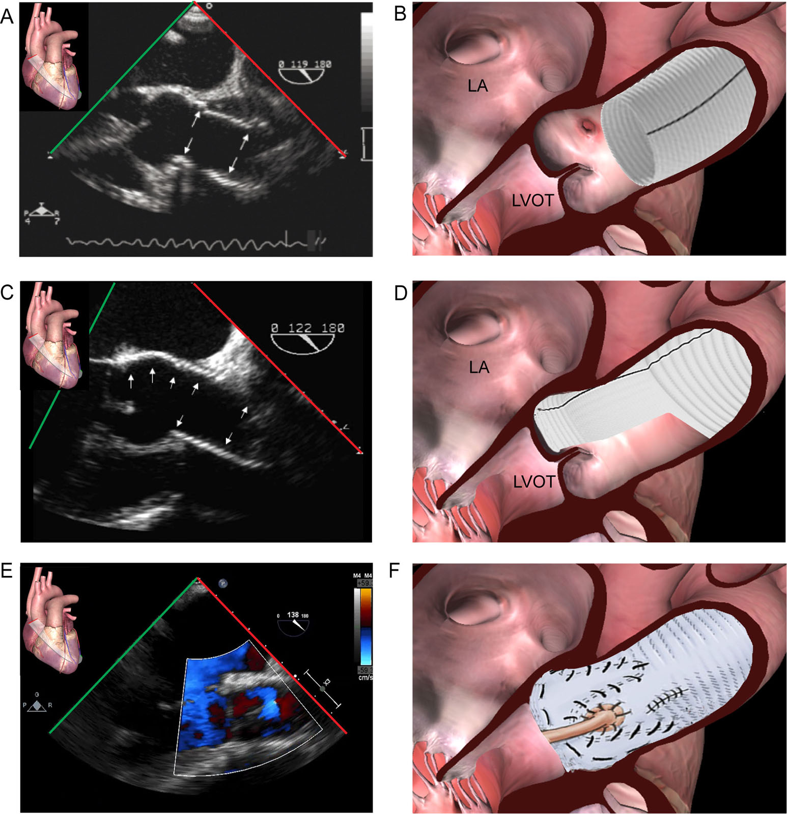
eFigure 15.31
AR type I repairs. These ME Asc Ao LAX views show different valve sparing procedures. (A,B) This is the typical tube graft sutured at the STJ with the preservation of the native AoV, sinuses of Valsalva and the coronary arteries to correct ascending aorta dilatation. (C,D) This shows a partial remodeling procedure with an hemi-graft. The ascending Ao and the left coronary sinus are replaced with a scalloped Valsalva prosthesis with the preservation of the native right and non-coronary sinuses. (E,F) The reimplantation (David) procedure preserves the native AoV and replaces the entire aortic root with a Dacron tube graft. There are different variations of this procedure depending on the root pathology. Abbreviations: Ao, aorta; AoV aortic valve; AR, aortic regurgitation; Asc Ao, ascending aorta; LA, left atrium; LAX, long-axis; LVOT, left ventricular outflow tract; ME, mid-esophageal; STJ, sinotubular junction.
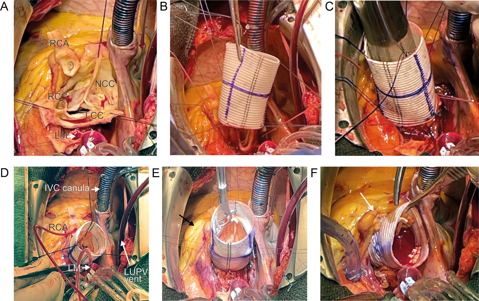
eFigure 15.33
Tirone David procedure. These intraoperative photos show the key procedural steps. (A) The initial step involves removing the entire aortic wall, leaving the crown-shaped valve and its commissures. (B) A straight Dacron graft is inserted around the aortic root to (C) the aortic annulus. (D) The commissures and valve are resuspended into the Dacron graft. Selective coronary cardioplegia is given in the RCA and LM. (E) During resuspension the effective height of all three cusps should be 8 mm for a tricuspid AoV. (F) The coronaries are re-anastomosed to the graft and a water test occurs. RCA anastomosis (arrow) on the graft. Abbreviations: AoV, aortic valve; IVC, inferior vena cava; LCC, left coronary cusp; LM, left main; LUPV, left upper pulmonary vein; NCC, non-coronary cusp; RCA, right coronary artery; RCC, right coronary cusp. Courtesy of Dr Demers.

eFigure 15.34
AR Type IB. (A,B) Color compare ME AoV LAX view shows the aneurysm of the root with a loss of central coaptation and a central AR jet. The ME AoV SAX view confirms the tethering of the cusps with ensuing central AR originating at the level of the loss of coaptation (not shown). (C,D) ME AoV LAX view with CFI post-reimplantation David procedure shows the native AoV inside the tube graft. Coaptation is perfect without residual AR. (E) The David procedure removes the entire aortic wall, only leaving the crown-shaped valve and its commissures that are sutured inside the Dacron tube graft. (F) The coronary arteries are reimplanted into the Dacron graft. Abbreviations: Ao, aorta; AoV, aortic valve; AR, aortic regurgitation; CFI, color flow imaging; LAX, long-axis; LVOT, left ventricular outflow tract; ME, mid-esophageal; SAX, short-axis. Source: Surgical films, courtesy of Prof. Gebrine El Khoury.
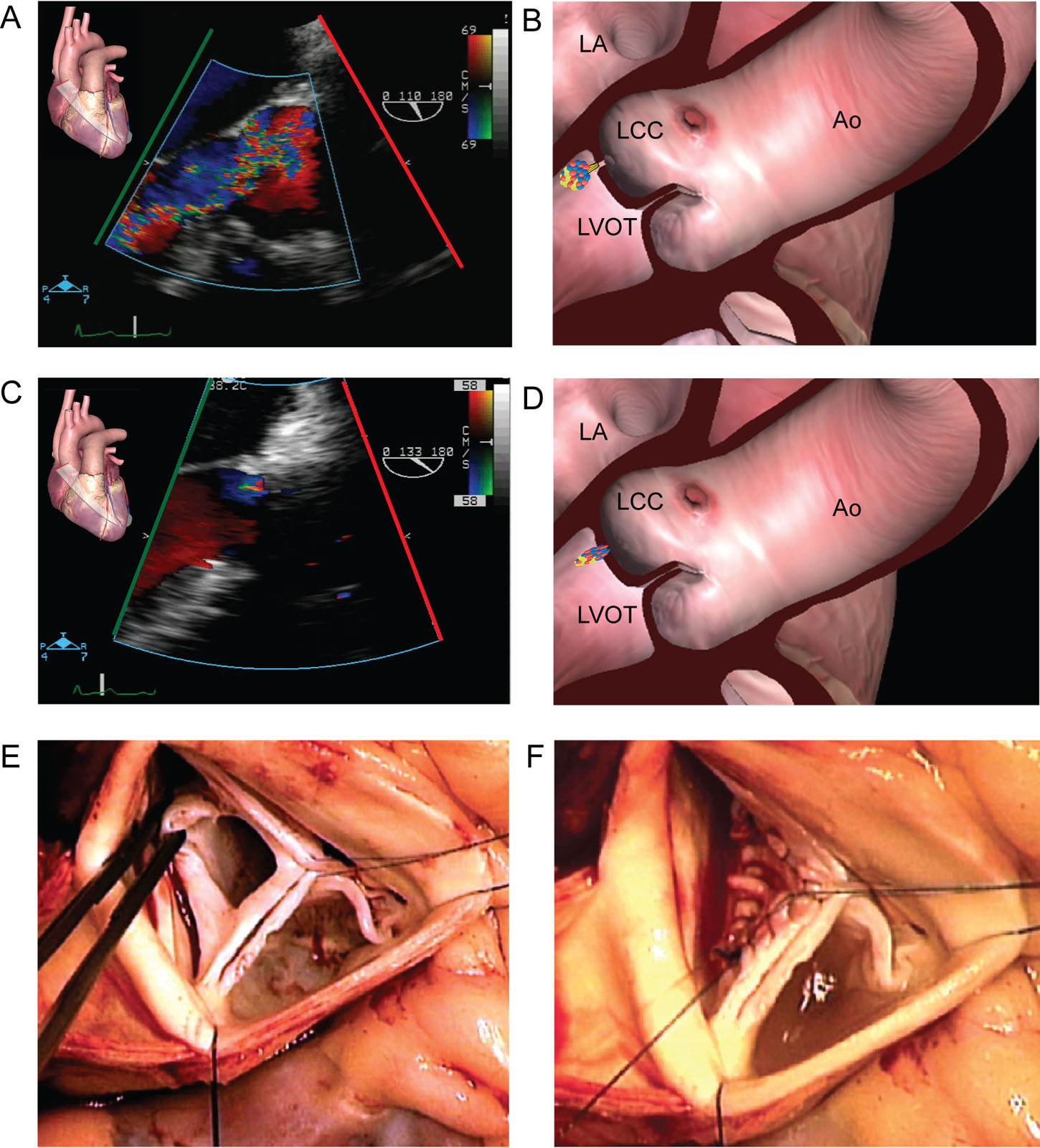
eFigure 15.35
AR Type ID from perforated LCC. This patient presents with a covered perforation of the LCC probably from healed endocarditis (A,B) ME AoV LAX view with CFI shows severe AR. (C,D) The same view after patch repair shows only trivial residual AR. (E,F) These are intraoperative photos (E) before and (F) after repair with a pericardial patch. Abbreviations: Ao, aorta; AoV, aortic valve; AR, aortic regurgitation; CFI, color flow imaging; LA, left atrium; LAX, long-axis; LCC, left coronary cusp; LVOT, left ventricular outflow tract; ME, mid-esophageal. Source: Surgical films, courtesy of Prof. Gebrine El Khoury.
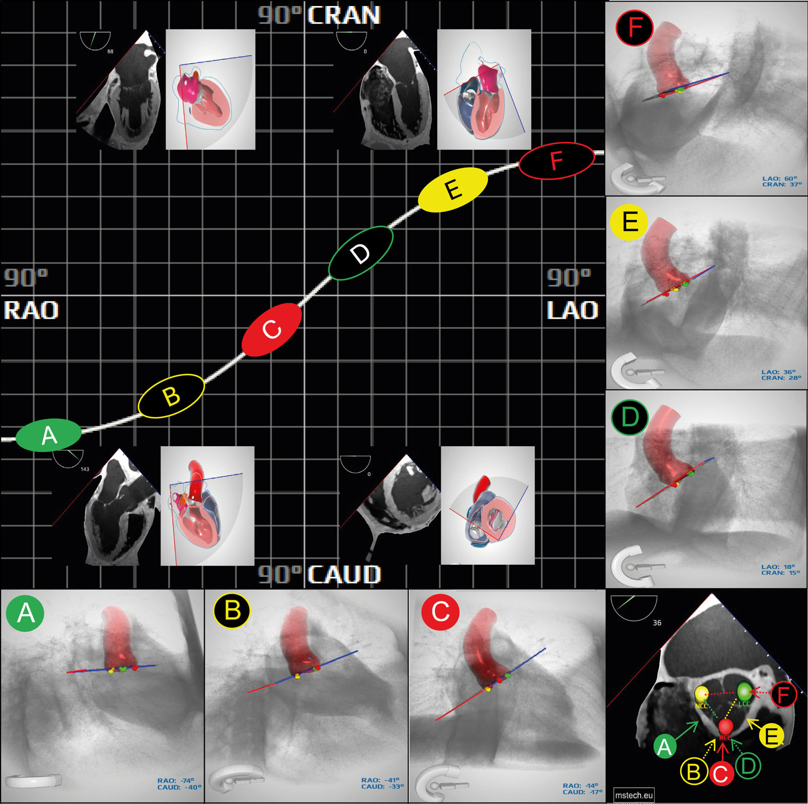
eFigure 15. 39
AoV S-curve, CT, fluoroscopic and TEE views. Depending on the selected CT, fluoroscopic, or corresponding TEE view, a different number of heart chambers will be optimally visualized. Those include a ME 2C (RAO-CRAN), ME 4C (LAO-CAUD), ME 3C or LAX (RAU-CAUD) and TG-SAX (LAO-CAUD). The left upper panel represent the AoV valve S-curve. In four quadrants corresponding view of the heart is shown. Right lower panel represents a TEE SAX view of the AoV. Markers on the AoV are located in the valsalva sinuses: left (green marker on the LCC), right (red marker in the RCC), non coronary (yellow marker in the NCC). Solid A, C, E circles represent fluoroscopy views with all Valsalva sinuses separated and visible symmetrically. The color of solid circle corresponds to a sinus locard centrally. Black B, D, F circles represent views with two sinuses overlaping. The color of the separated sinus corresponds to the circle outline color. Variations may be identified depending on different orientation of cardiac structures. Abbreviations: 2C, two-chamber; 3C, three-chamber; 4C, four-chamber; AoV, aortic valve; CAUD, caudal; CRAN, cranial; CT, computed tomography; LAO, left anterior oblique; LAX, long-axis; LCC, left coronary cusp; ME, mid-esophageal; NCC, non-coronary cusp; RAO, right anterior oblique; RCC, right coronary cusp; TEE, transesophageal echocardiography. Curtesy of Andrzej Gackowski from Medical Simulation Technology adapted from Zgheib et al.119
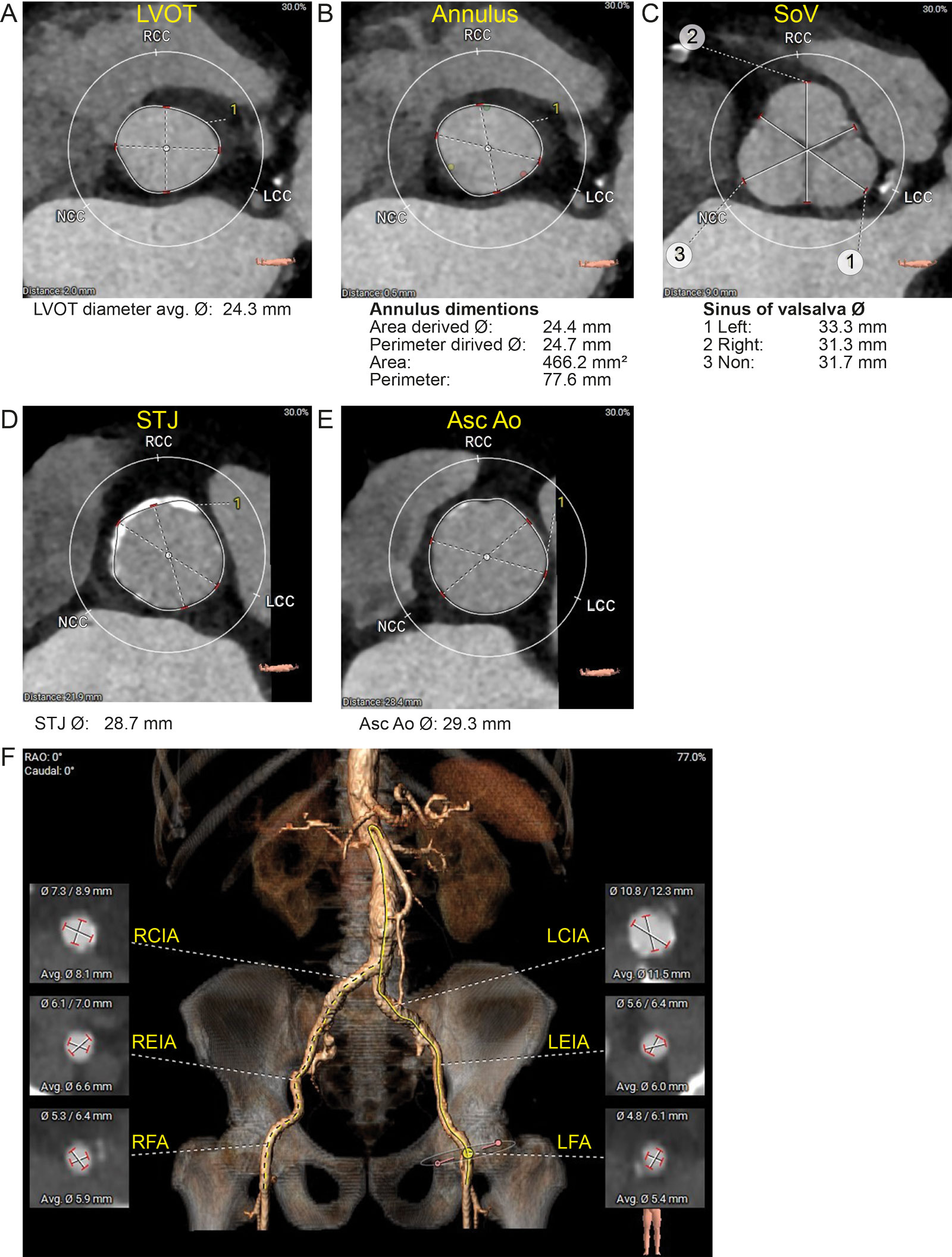
eFigure 15.41
Pre-TAVR evaluation. (A-E) CT reconstruction of the aortic root allows for measurements of the transverse LVOT, AoV annulus, SoV, STJ and Asc Ao transverse diameter. (F) CT reconstruction allows for measurements of proximal lower extremity aortic branches. Abbreviations: Asc Ao, ascending aorta; AVG, average; CT, computed tomography; LCC, left coronary cusp; LCIA, left common iliac artery; LEIA, left external iliac artery; LFA, left femoral artery; LVOT, left ventricular outflow tract; NCC, none-coronary cusp; RAO, right anterior oblique; RCC, right coronary cusp; RCIA, right common iliac artery; REIA, left external iliac artery; RFA, right femoral artery; SoV, sinus of Valsalva; STJ, sinotubular junction; TAVR, transcatheter aortic valve replacement.
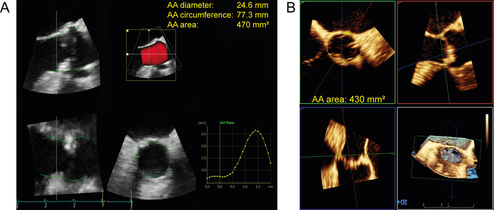
eFigure 15.42
Aortic annulus measurements. These are examples of aortic annular measurements using MPR with a 3D dataset acquired by (A) General Electric and Philips (B) ultrasound systems. Abbreviations: 3D, three-dimensional; AA, aortic annulus; MPR, multiplanar reconstruction.
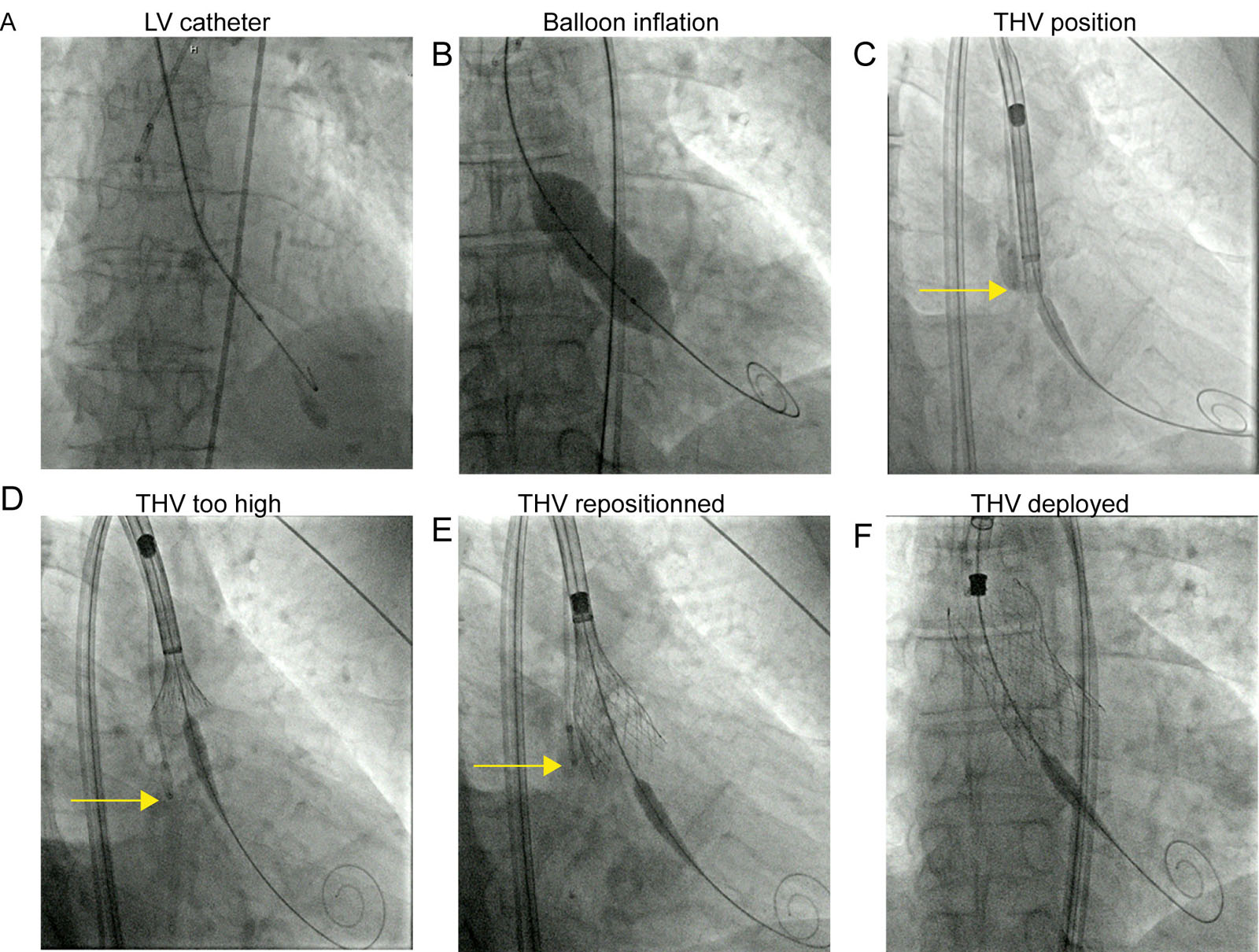
eFigure 15. 43
THV procedure with a Medtronic Evolut ProTM. These are fluoroscopic images during THV procedure. (A) An LV catheter is inserted to pace and measure the Plv and Pa. (B) Balloon inflation (optional for Medtronic THV Evolut type) occurs during controlled pacing. (C) The THV is positioned using the catheter tip in the sinus of Valsalva (arrow) initially. (D) During valve deployment, cephalad motion resulted in a THV which was too high in relation to the aortic annulus (arrow). (E) This required the repositioning of the THV at the AoV annular level. (F) This is the final position of the THV.Abbreviations: AoV, aortic valve; LV, left ventricular; Pa, arterial pressure; Plv, left ventricular pressure; THV, transcatheter heart valve.
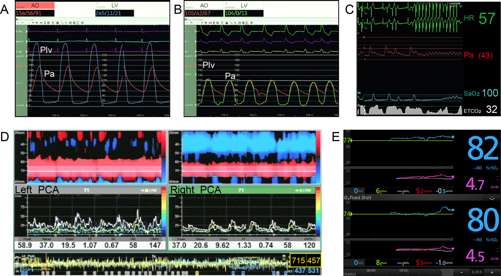
eFigure 15.44
THV procedure. (A,B) These pressure traces show the AoV pressure gradients before and after THV. (C) Hemodynamic data during pacing and balloon inflation show an absence of peripheral perfusion. (D) Transcranial Doppler associated with 715 and 457 high intensity transient signals on the left (L) and on the right (R) at the end of the procedure. The DM% increased at 147% and 120% compared to baseline mean TCD velocities. (E) In addition, there was an increase in both L and R regional oxygen saturation (rSO2).Abbreviations: %rSO2, percent change in rSO2; Dbase%, percent change in regional oxygen saturation compared to baseline; DcHbi, change in total hemoglobin index; DHHbi, change in deoxygenated hemoglobin index; DO2Hbi, change in oxygenated hemoglobin index; DSpO2%, peripheral oximetry change; AoV, aortic valve; AUC, area under curve; DM%, % difference of mean velocity; PI, pulsatility index; PCA, posterior cerebral artery; Plv, left ventricular pressure; RI, resistance index; SaO2, arterial oxygen saturation; TVH, transcatheter heart valve.
Videos
Chapter 15 Fig07AB
Chapter 15 Fig07D
Chapter 15 Fig07E
Chapter 15 Fig08A
Chapter 15 Fig08B
Chapter 15 Fig08C
Chapter 15 Fig08D
Chapter 15 Fig08E
Chapter 15 Fig08F
Chapter 15 Fig09A
Chapter 15 Fig09C
Chapter 15 Fig10C
Chapter 15 Fig10D
Chapter 15 Fig12A
Chapter 15 Fig12BD
Chapter 15 Fig13A
Chapter 15 Fig13B
Chapter 15 Fig14AC
Chapter 15 Fig14E
Chapter 15 fig15A
Chapter 15 Fig15ABC
Chapter 15 Fig16A
Chapter 15 Fig16C
Chapter 15 Fig16D
Chapter 15 Fig17A
Chapter 15 Fig17B
Chapter 15 Fig17DE
Chapter 15 Fig18A
Chapter 15 Fig18C
Chapter 15 Fig19A
Chapter 15 Fig20A
Chapter 15 Fig20C
Chapter 15 Fig21A
Chapter 15 Fig21B
Chapter 15 Fig21DE
Chapter 15 Fig21F
Chapter 15 Fig22A
Chapter 15 Fig22B
Chapter 15 Fig22D
Chapter 15 Fig24A
Chapter 15 Fig24C
Chapter 15 Fig25A
Chapter 15 Fig25C
Chapter 15 Fig25E
Chapter 15 Fig26A
Chapter 15 Fig26B
Chapter 15 Fig31E
Chapter 15 Fig32E
Chapter 15 Fig33B
Chapter 15 Fig33D
Chapter 15 Fig33E
Chapter 15 Fig34A
Chapter 15 Fig34C
Chapter 15 Fig34EF
Chapter 15 Fig35A
Chapter 15 Fig35C
Chapter 15 Fig36A
Chapter 15 Fig36C
Chapter 15 Fig38A
Chapter 15 Fig38C
Chapter 15 Fig38DE
Chapter 15 Fig38F
Chapter 15 Fig39
Chapter 15 Fig43DE
Chapter 15 Fig44
Chapter 15 Fig46AC
Chapter 15 Fig47ACDE
Chapter 15 Fig48A
Chapter 15 Fig48D
Chapter 15 Fig49A
Chapter 15 Fig49B
Chapter 15 Fig50
Chapter 15 Fig51A
Chapter 15 Fig51C
Tables
eTable 15.6 Normal Reference Values of EOAs for the Aortic Prostheses
| 19 | 21 | 23 | 25 | 27 | 29 | |
| Aortic stented bioprosthesis | ||||||
| Mosaic | 1.1±0.2 | 1.2±0.3 | 1.4±0.3 | 1.7±0.4 | 1.8±0.4 | 2.0±0.4 |
| Hancock II | - | 1.2±0.1 | 1.3±0.2 | 1.5±0.2 | 1.6±0.2 | 1.6±0.2 |
| CE Perimount | 1.1±0.3 | 1.3±0.4 | 1.5±0.4 | 1.8±0.4 | 2.1±0.4 | 2.2±0.4 |
| CE Magna* | 1.3±0.3 | 1.5±0.3 | 1.8±0.4 | 2.1±0.5 | - | - |
| Biocor (Epic)* | 1.0±0.3 | 1.3±0.5 | 1.4±0.5 | 1.9±0.7 | - | - |
| Mitroflow* | 1.1±0.1 | 1.2±0.1 | 1.4±0.3 | 1.6±0.3 | 1.8±0.3- | - |
| Trifecta | 1.4 | 1.6 | 1.8 | 2.0 | 2.2 | 2.4 |
| Aortic stentless bioprosthesis | ||||||
| Medtronic Freestyle | 1.2±0.2 | 1.4±0.2 | 1.5±0.3 | 2.0±0.4 | 2.3±0.5 | - |
| St Jude Medical Toronto SPV | - | 1.3±0.3 | 1.5±0.3 | 1.7±0.8 | 2.1±0.7 | 2.7±1.0 |
| Prima Edwards | 1.3±0.3 | 1.6±0.3 | 1.9±0.4 | |||
| Aortic mechanical prostheses | ||||||
| Medtronic-Hall | 1.2±0.2 | 1.3±0.2 | - | - | - | - |
| Medtronic Advantage* | - | 1.7±0.2 | 2.2±0.3 | 2.8±0.6 | 3.3±0.7 | 3.9±0.7 |
| St Jude Medical Standard | 1.0±0.2 | 1.4±0.2 | 1.5±0.5 | 2.1±0.4 | 2.7±0.6 | 3.2±0.3 |
| St Jude Medical Regent | 1.6±0.4 | 2.0±0.7 | 2.2±0.9 | 2.5±0.9 | 3.6±1.3 | 4.4±0.6 |
| MCRI On-X | 1.5±0.2 | 1.7±0.4 | 2.0±0.6 | 2.4±0.8 | 3.2±0.6 | 3.2±0.6 |
| Carbomedics Standard and Top Hat | 1.0±0.4 | 1.5±0.3 | 1.7±0.3 | 2.0±0.4 | 2.5±0.4 | 2.6±0.4 |
| ATS Medical a | 1.1±0.3 | 1.6±0.4 | 1.8±0.5 | 1.9±0.3 | 2.3±0.8 |
EOA is expressed as mean values available in the literature.*These results are based on a limited number of patients and thus should be interpreted with caution. Prostheses EAO is expressed as mean values available in the literature. Further studies are needed to validate these reference values. aFor the ATS medical valve, the label valve sizes are 18, 20, 22, 24 and 26mm. High velocities are common in size 19 or 21 prostheses. Adapted with permission from Pibarot et al. 106. Abbreviations: CE, Carpentier-Edwards; EAO, effective orifice area
eTable 15.10 AVR indications in patients undergoing CABG surgery
Class I |
AVR is indicated with severe AS who meet the criteria for valve replacement. (LOE: C) |
Class IIa |
AVR is reasonable with moderate AS (MG 30–50 mmHg or Doppler velocity 3–4 m/s). (LOE: B) |
Class IIb |
AVR may be considered with mild AS (MG < 30 mmHg or Doppler velocity < 3 m/s) when there is evidence, such as moderate-to-severe valve calcification, that progression may be rapid. (LOE: C) |
Abbreviations: AS, aortic stenosis; AVR, aortic valve replacement; CABG, coronary artery bypass graft; LOE, level of evidence; MG, mean gradient. Adapted from Bonow et al.110 |
|
eTable 15.12 TEE imaging sequence during THV
TEE view |
Probe position and maneuver |
Periprocedural function of views |
2D ME 5C |
0-10° |
1. Retrograde wires crossing into LV, with a clear view of LV apex |
2D ME LAX |
120-140° |
|
2D ME LAX |
120-140° |
1. Prosthesis positioning during balloon dilation and live depiction of AoV calcification behavior during implantation (especially when less visible fluoroscopically) |
3D ME LAX |
30-45° |
|
2D multiplane imaging (ME LAX and SAX) |
||
2D ME 5C |
0-10° |
1. CFI post-procedure for success and complications |
2D ME SAX |
120-140° |
|
Live 3D-MPR |
30-45° |
|
Abbreviations: 2D, two-dimensional; 3D, three dimensional; 5C, five-chamber; AoV, aortic valve; CFI, color flow imaging; LAX, long-axis; LV, left ventricular; ME, mid-esophageal; MPR, multiplane reconstruction; MV, mitral valve; SAX, short-axis; TEE, transesophageal echocardiography; THV, transcatheter heart valve. Adapted from Raja-Shariff et al. 1 |
||
eTable 15.13 3D area THV sizing for balloon-expandable valves (Edwards Sapien 3 Ultra)
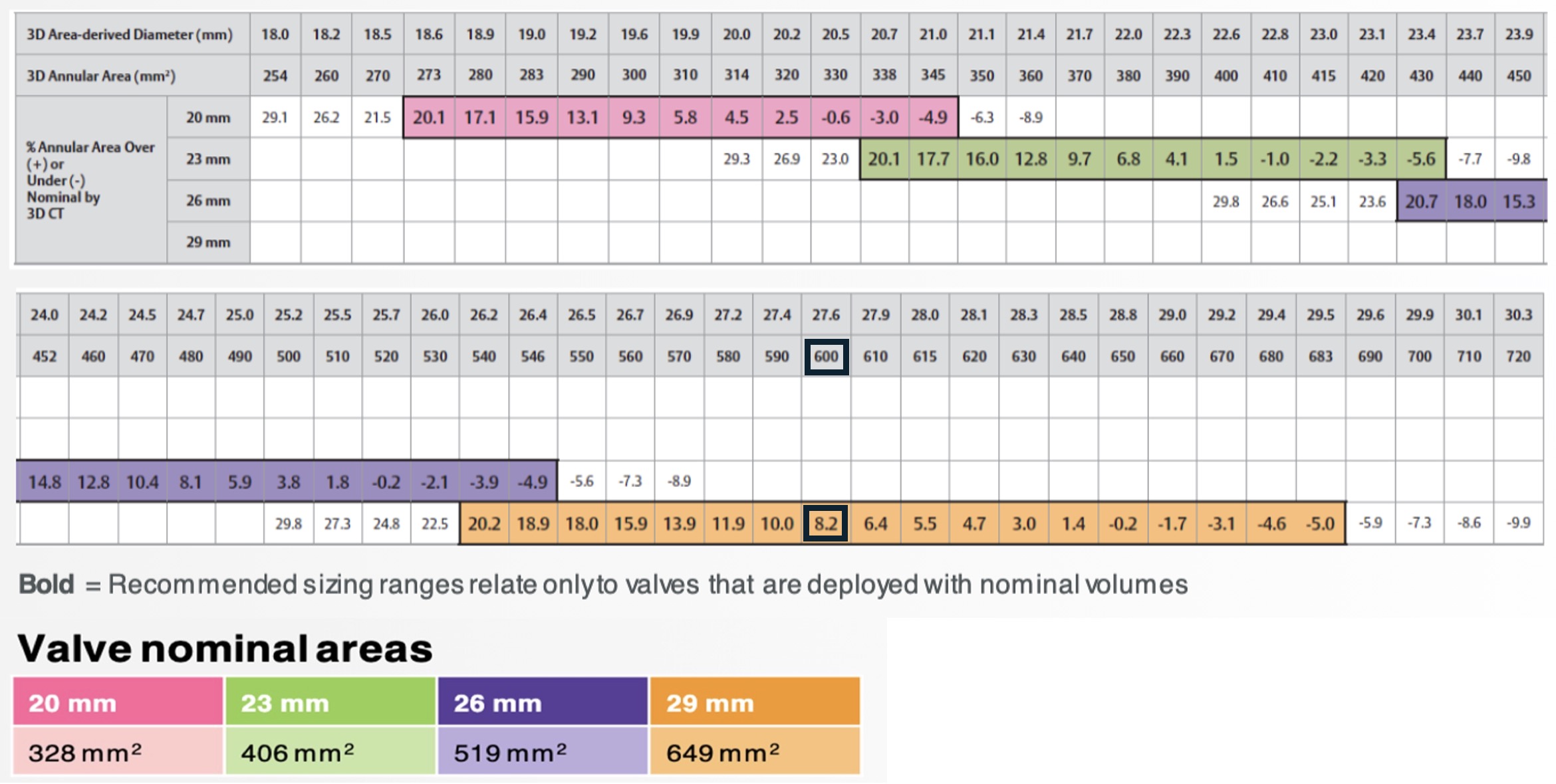
3D annular area of the patient = 600 mm²
Prosthesis selection = 29 mm
Area of the 29 mm THV = 649 mm²
Oversizing = ([ Area THV/ area patient valve ] – 1 ) X 100
Oversizinig = ([ 649 mm² / 600 mm² ] – 1 ) X 100 = 8.2% (ideal ± 10%)
For Edwards Sapien valve, the 3D annular area will determine the valve prosthesis size. For instance, if the 3D annular area is 600 mm², then a 29 mm THV will be selected. The oversizing will be 8.2% (Ideal ± 10%). If too much oversizing, there is a risk of rupture. If the oversizing is too small, then there is a risk of paravalvualar leak or embolization. The 3D area derived diameter corresponds to a mean diameter. All values are presented based on nominal recommended inflation volume. Systolic measurements are recommended. Abbreviations: 3D, three-dimensional; CT, computed tomography; THV, transcatheter heart valve. (Curtesy of Edwards Lifesciences)
eTable 15.14 THV sizing for self-expanding valves (Evolut FX)
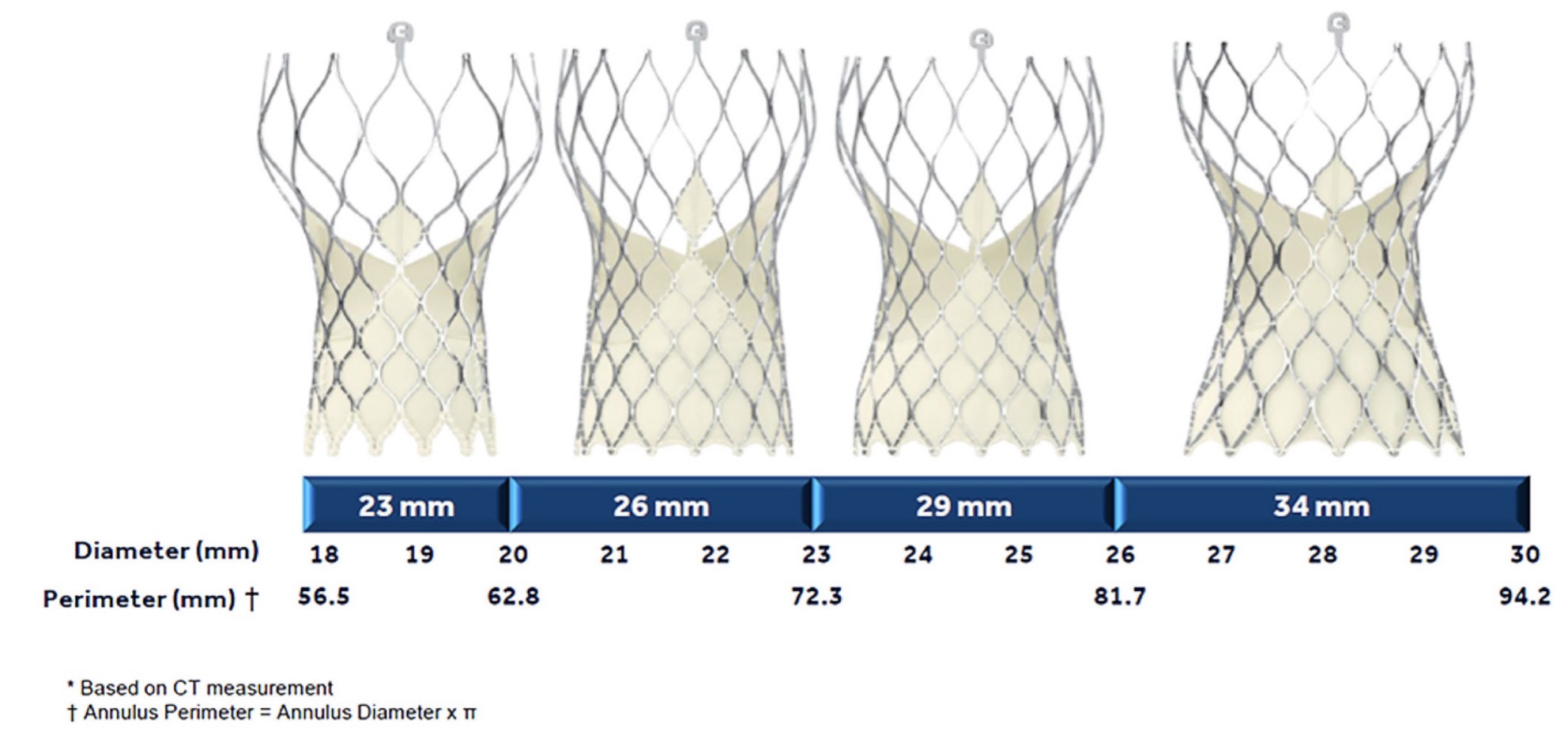
The selection of a self-expanding THV is based on the perimeter (mm) or the annulus mean diameter. A calculation is made for sizing:
Sizing = Prosthesis perimeter – Annulus derived-perimeter
Annulus derived perimeter
If annulus derived- perimeter = 26 mm
If Evolut FX 34 mm is selected
Sizing = (34-26)/26 = 31% oversizing (normal = 13 to 31%)
Abbreviations: CT, computed tomography; THV, transcatheter heart valve
CT, computed tomography; ADD
eTable 15.15 Cardiac structural complications
Major (One of the following) |
|
Minor (One of the following) |
|
*Aortic annulus, left ventricular outflow tract, ventricular septum, left or right ventricle, atrial septum, left or right atrium, mitral valve apparatus, tricuspid valve apparatus, coronary artery, and coronary sinus. Also includes any new inter-cardiac cavity communication (e.g. VSD), and new left-to-right or right-to-left shunt. |
Abbreviations: VARC, Valve Academic Research Consortium |
Adapted from Varc-3107 |
eTable 15.16 Other acute procedural and technical valve related complications*
Conversion to open sternotomy or thoracotomy using CPB secondary to any procedure-related complication or failed intended transcatheter approach. Should be classified as:
|
|
|
|
|
*Individual events should be collected so that specific event rates can be determined. |