Figures
eFigure 33.2
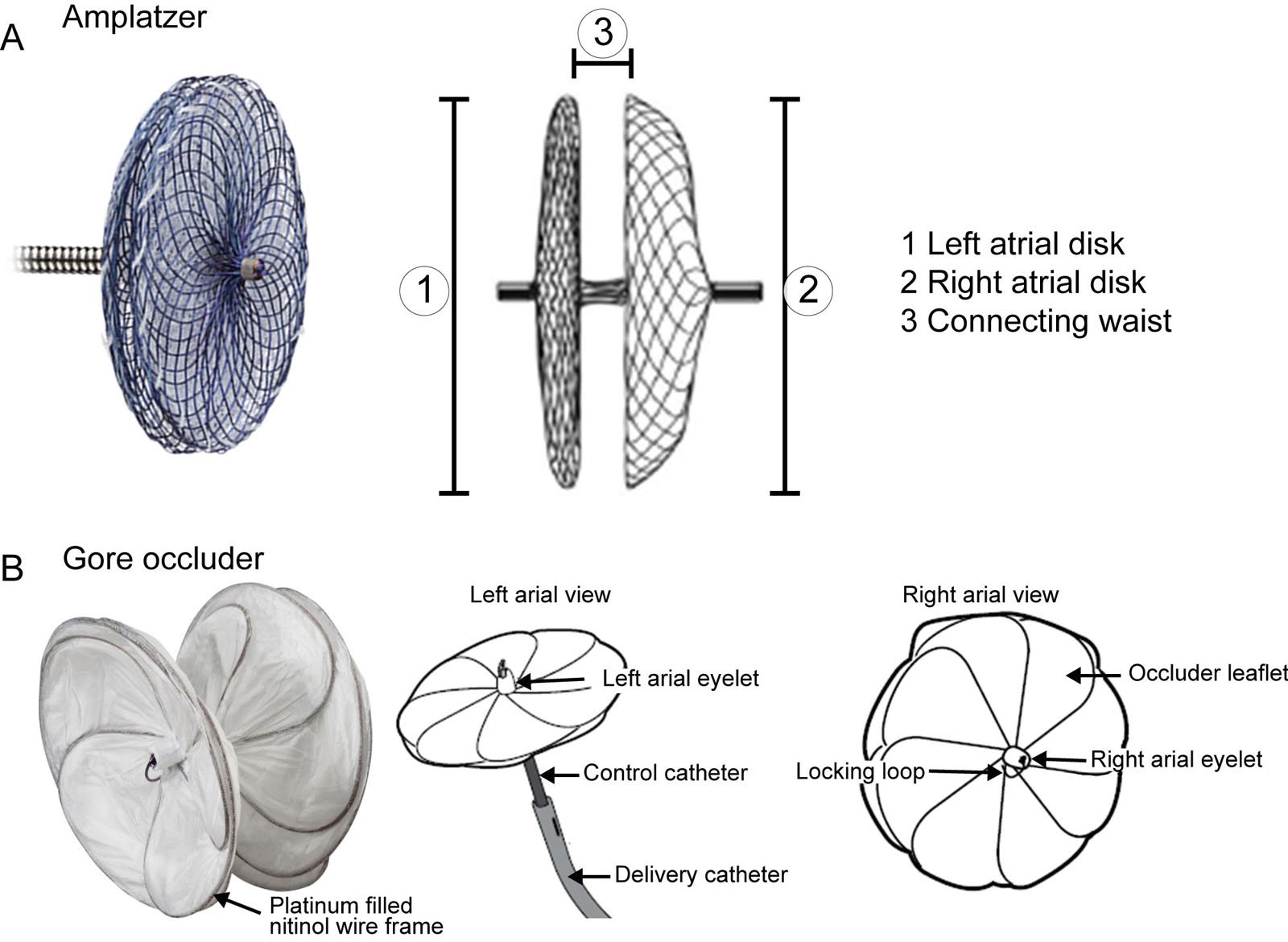
Percutaneous closure devices. These are examples of commercially available percutaneous closure devices, including the (A) Amplatzer™ Cribriform Multi-Fenestrated Septal Occluder (Abbott). (B) Gore Cardioform ASD occluder delivery system. Source: Photo courtesy of Abbott https://www.cardiovascular.abbott/us/en/hcp/products/structural-heart/structural-interventions.html and W.L. Gore & Associates, Inc. https://www.goremedical.com/products/cardioform/septal-occluder
eFigure 33.3
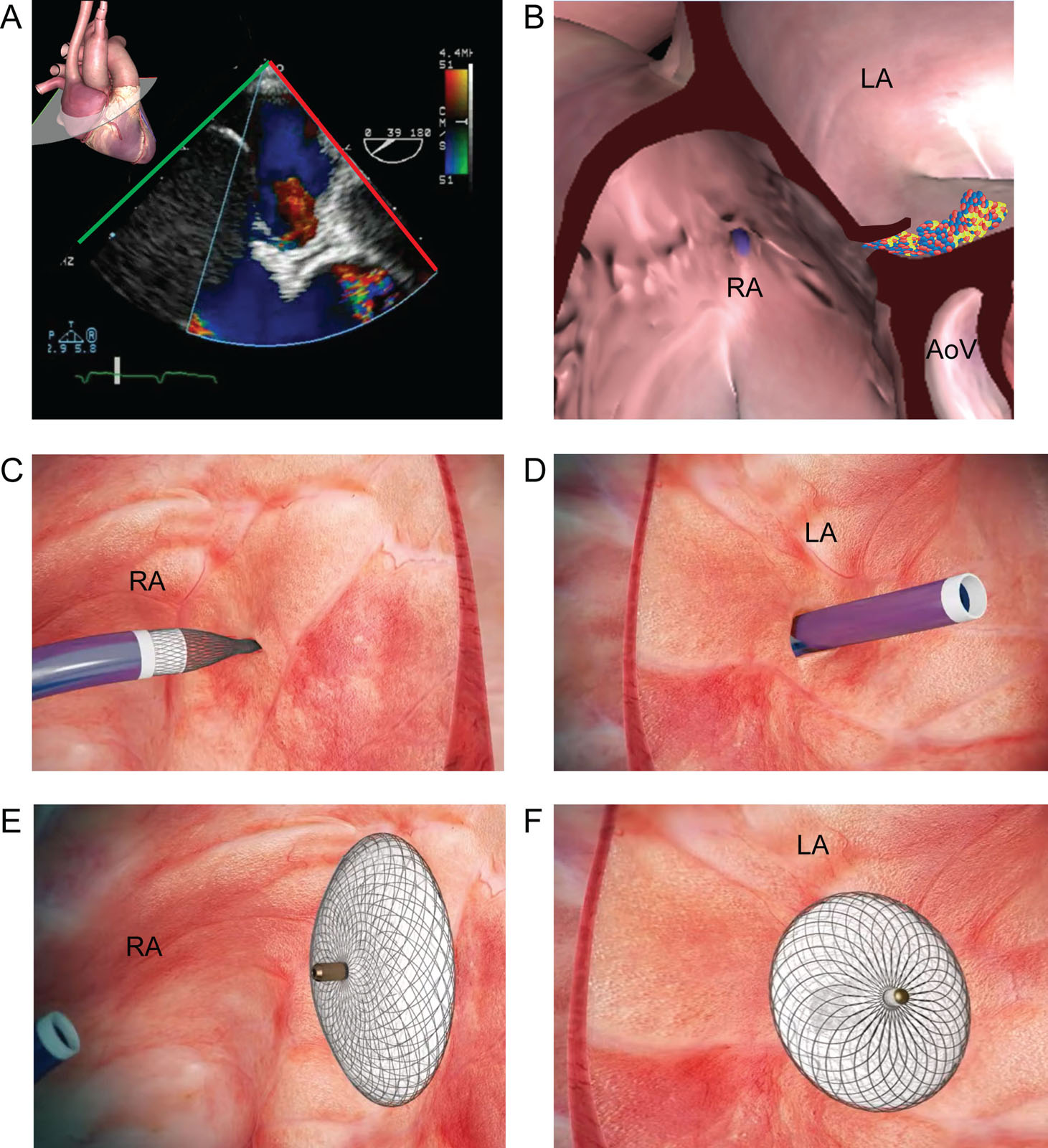
PFO after LVAD. This is a hypoxemic patient post LVAD implantation with a PFO. (A,B) Zoomed ME RV inflow/outflow view with CFI at 39° shows a significant right-to-left shunt through a PFO (arrow). (C,D) Insertion of the catheter through the interatrial septum and (E,F) PFO closure using a trans-catheter Amplatzer™ device (Abbott) closure. Abbreviations: AoV, aortic valve; CFI, color flow imaging; LA, left atrium; LVAD, left ventricular assist device; ME, mid-esophageal; PFO, patent foramen ovale; RA, right atrium; RV, right ventricular. Photo courtesy of Abbott.
eFigure 33.5
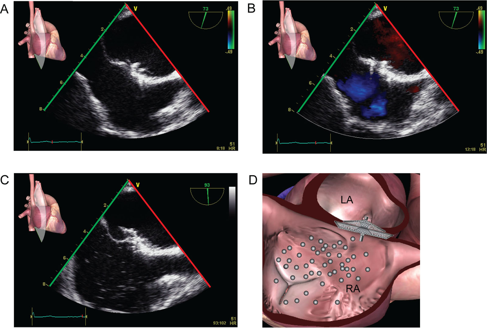
Device closure function. These ME bicaval views show the assessment of residual shunt through the PFO after closure device implantation. (A) This is a successfully deployed BioSTAR® device through a PFO undergoing (B) assessment of residual left-to-right shunt with CFI and (C, D) residual right-to-left shunt with agitated saline micro-bubble contrast injection. Abbreviations: CFI, color flow imaging; LA, left atrium; ME, mid-esophageal; PFO, patent foramen ovale; RA, right atrium.
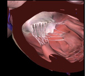
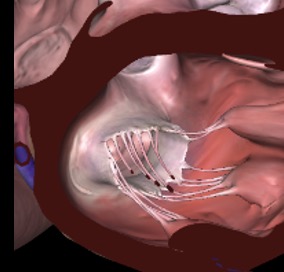
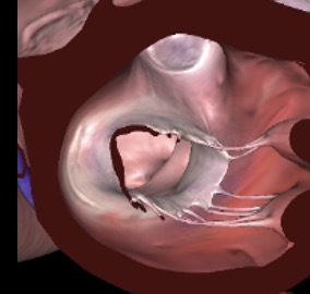
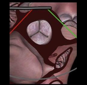
eFigure 33.6
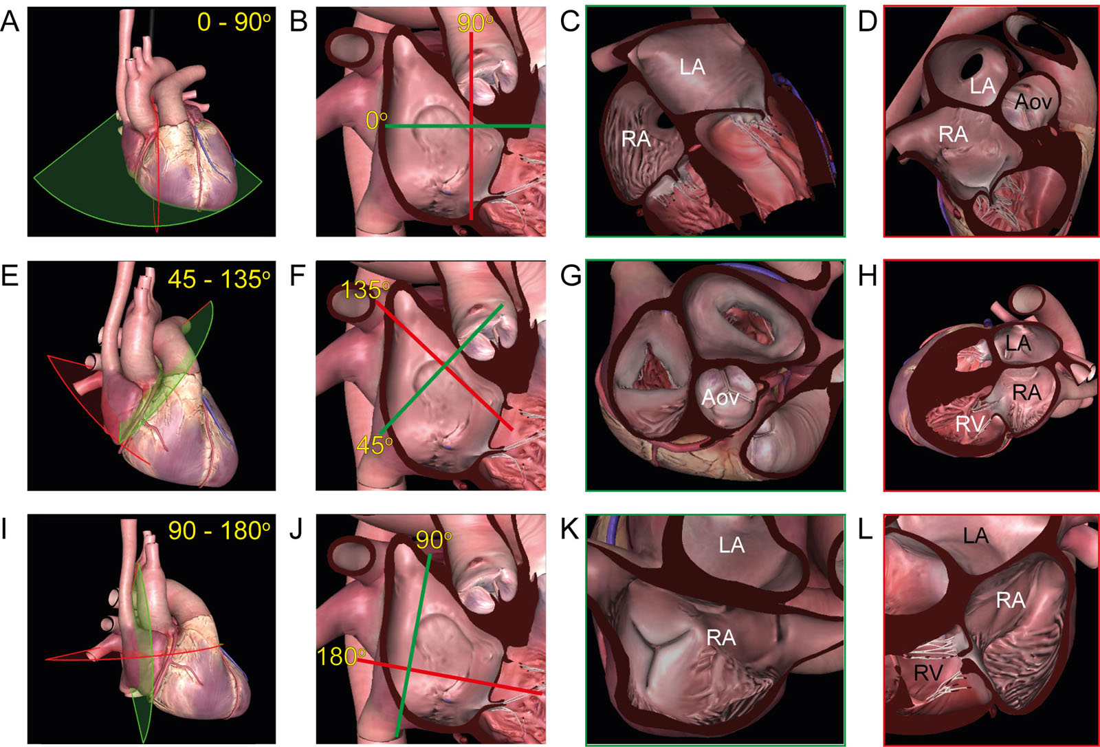
IAS biplane views. These diagrams show the complete evaluation of the IAS using biplane ME views at (A-D) 0-90°, (E-H) 45-135° and (I-L) 90-180°. The green and red lines indicate the initial and perpendicular plane orientation. Abbreviations: AoV, aortic valve; IAS, interatrial septum; LA, left atrium; ME, mid-esophageal; RA, right atrium; RV, right ventricle. Adapted from Raja Shariff et al.70
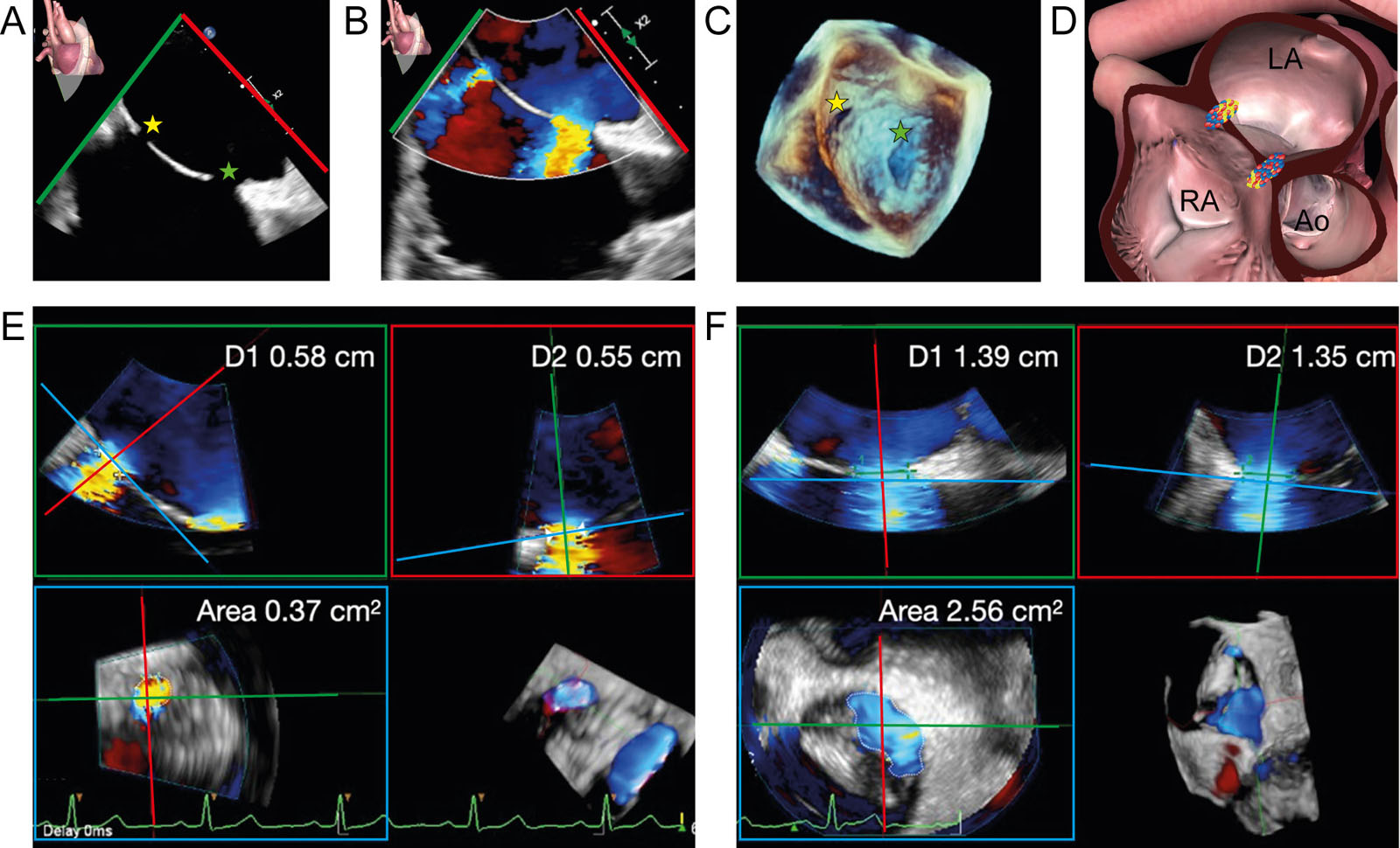
eFigure 33.9
Secundum ASD 3D TEE assessment. (A-D) Zoomed ME bicaval 2D without and with CFI and 3D dataset of the IAS show a secundum ASD (green star) and a smaller, iatrogenic infero-posterior ASD (yellow star) from a previous atrial septostomy for atrial fibrillation ablation. (E, F) Analysis of the 3D dataset using MPR enables measurement of the size of both defects (area and orthogonal diameters, D1 and D2). Abbreviations: 2D, two-dimensional; 3D, three-dimensional; Ao, aorta; ASD, atrial septal defect; CFI, color flow imaging; D, diameter; IAS, interatrial septum; LA, left atrium; ME, mid-esophageal; MPR, multiplanar reconstruction; RA, right atrium; TEE, transesophageal echocardiography.
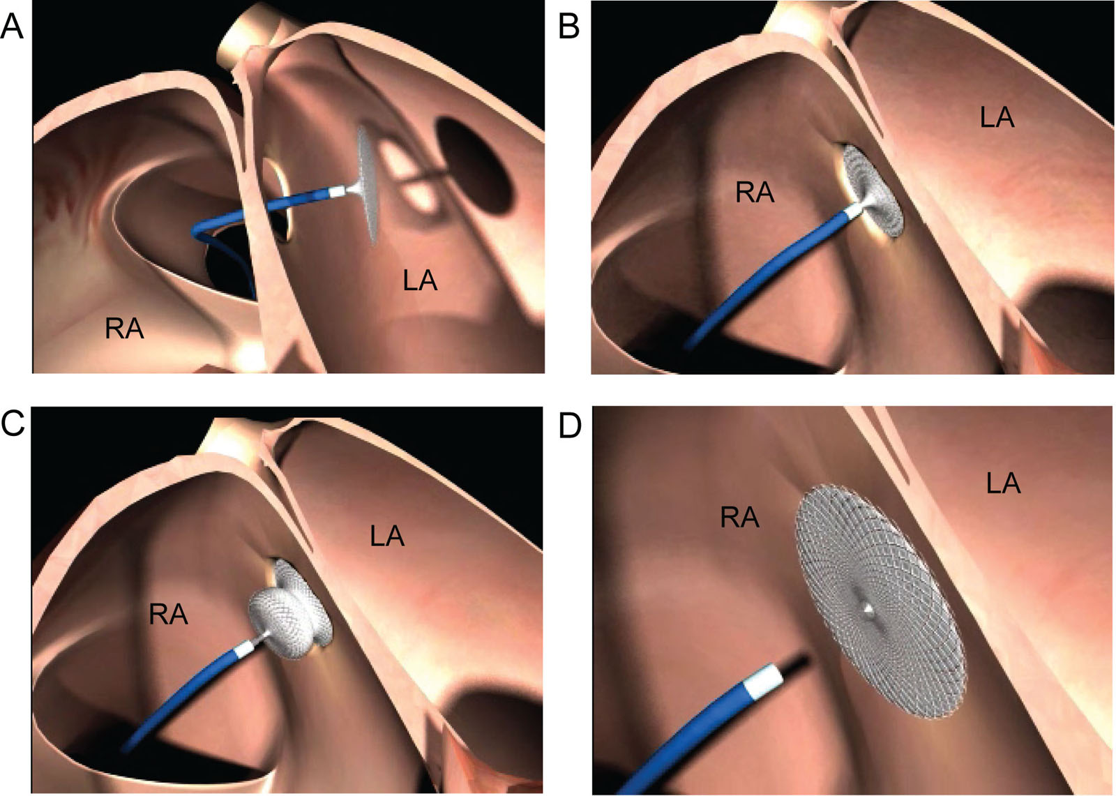
eFigure 33.12
Percutaneous ASD device closure. These diagrams illustrate the sequence of events during a percutaneous AmplatzerTM device closure of a secundum ASD. (A) The catheter with the device passes through the ASD from the RA to the LA. (B) The operator deploys the LA disc and pulls it snugly against the LA side of the IAS. (C) The RA disc deploys against the RA side of the IAS. (D) The definitive device release is by unscrewing the cable from it and retrieving both the cable and the delivery sheath. Abbreviations: ASD, atrial septal defect; IAS, interatrial septum; LA, left atrium; RA, right atrium. Source: courtesy of Abbott.
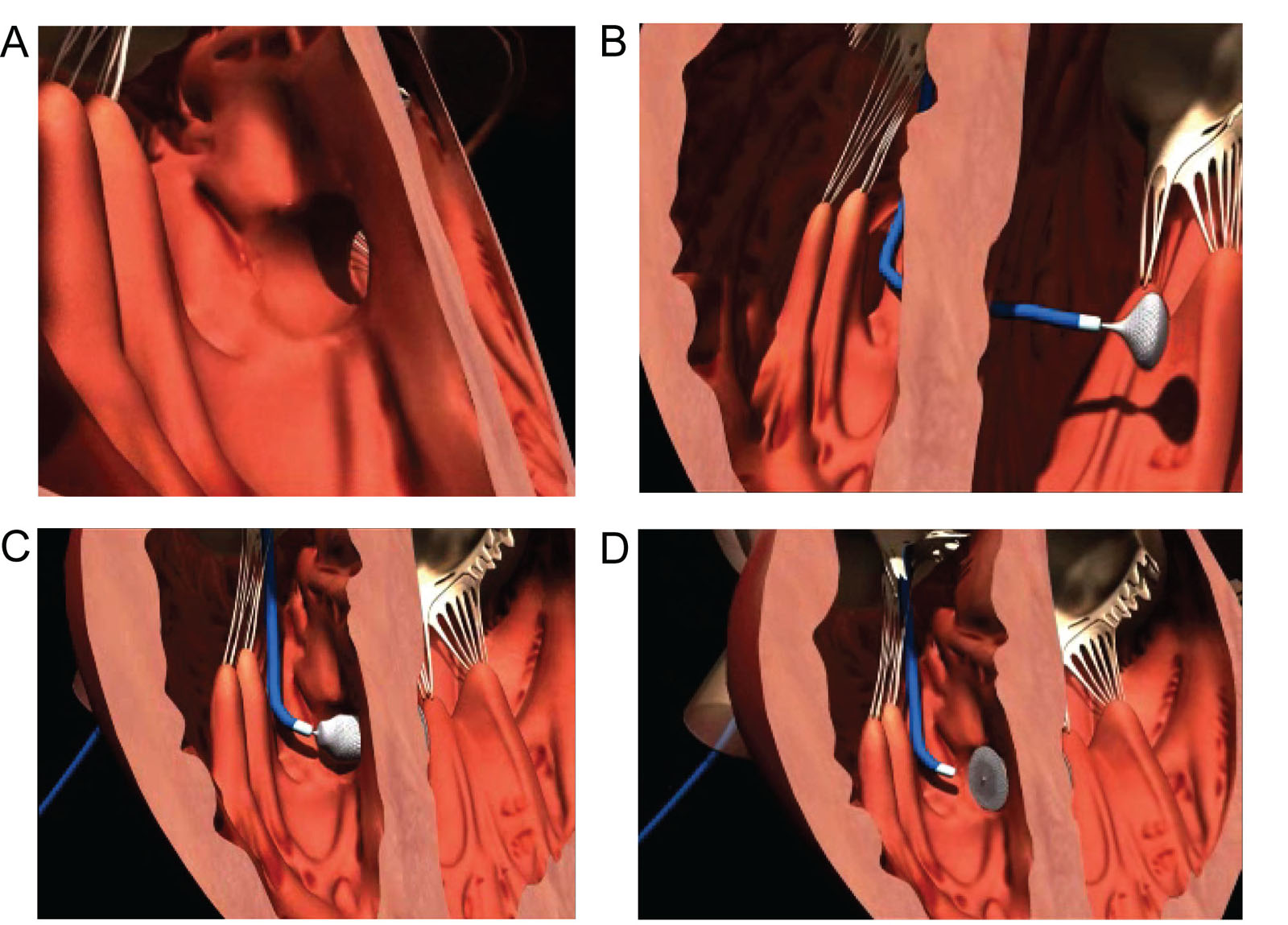
eFigure 33.16
Percutaneous VSD device closure. These diagrams illustrate the sequence of events during a percutaneous AmplatzerTM device closure of a muscular VSD. (A) The catheter holding the device passes through the VSD from the RV to the LV. (B) The operator deploys the LV disc and pulls it snugly against the LV side of the IVS. (C) The RV disc deploys against the RV side of the IVS. (D) The introducer cable detaches from the device and is removed with its delivery sheath. Abbreviations: IVS, interventricular septum; LV, left ventricle or left ventricular; RV, right ventricle or right ventricular; VSD, ventricular septal defects. Source: Courtesy of Abbott.
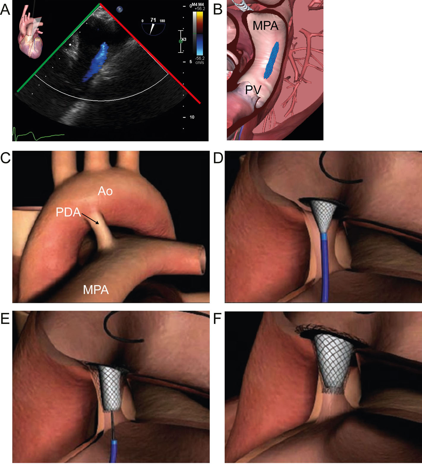
eFigure 33.19
PDA device closure. (A,B) UE view of a PDA. (C-F) These diagrams illustrate the sequence of events during the percutaneous device closure of a PDA. Abbreviation: Ao, aortic valve; MPA, main pulmonary artery; PDA, patent ductus arteriosus; PV, pulmonic valve; UE, upper esophageal. Source: Courtesy of Abbott
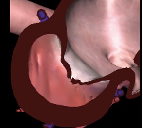
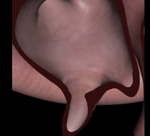
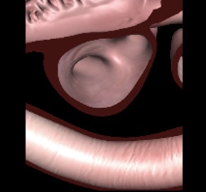
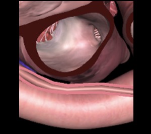
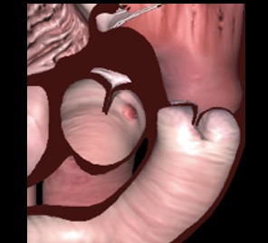
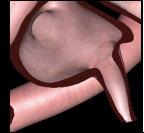
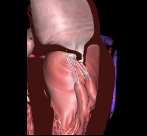
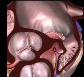
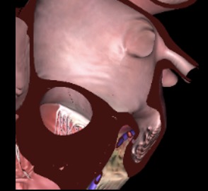
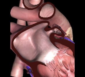
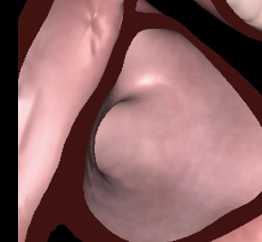
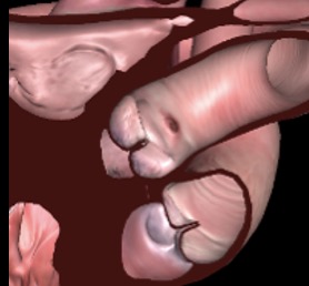
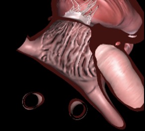
eFigure 33.23
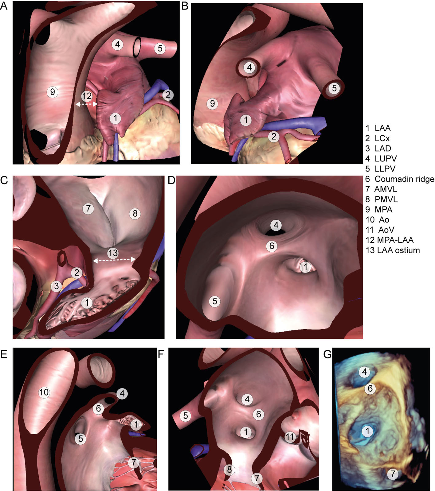
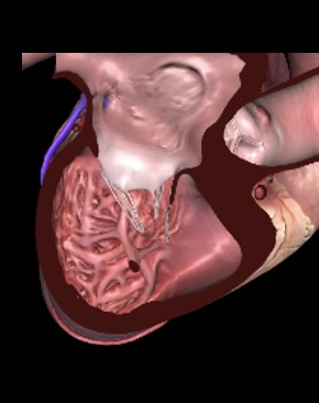
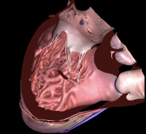
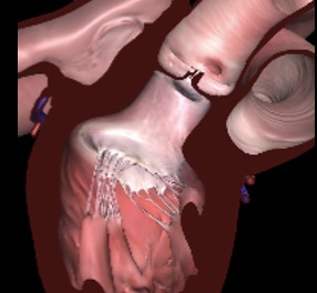
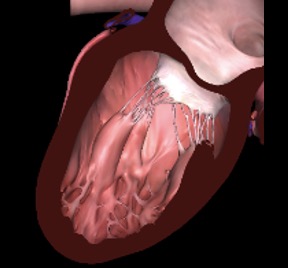
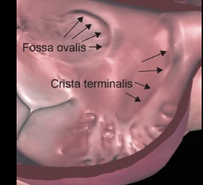
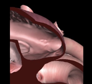
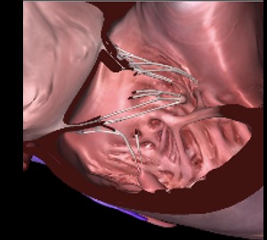
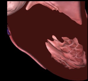
LAA anatomy. The LAA appears from the external perspective (A) anterior and (B) left side and (C) the internal perspective. Note the proximity of the MPA to the LAA. (D-F) These diagrams show the relationship of the LAA to surrounding structures, including the (D) coumadin ridge, (E) PV and (F) with MV. (G) This is a 3D dataset from the LA perspective showing the orifice of the LAA and LUPV. Abbreviations: 3D, three-dimensional; AMVL, anterior mitral valve leaflet; Ao, aorta; AoV, aortic valve; LA, left atrium; LAA, left atrial appendage; LAD, left anterior descending artery; LCx where, left circumflex artery; LLPV where, left lower pulmonary vein; LUPV where, left upper pulmonary vein; MPA, main pulmonary artery; MV, mitral valve; PMVL, posterior mitral valve leaflet; PV, pulmonic valve.
eFigure 33.28
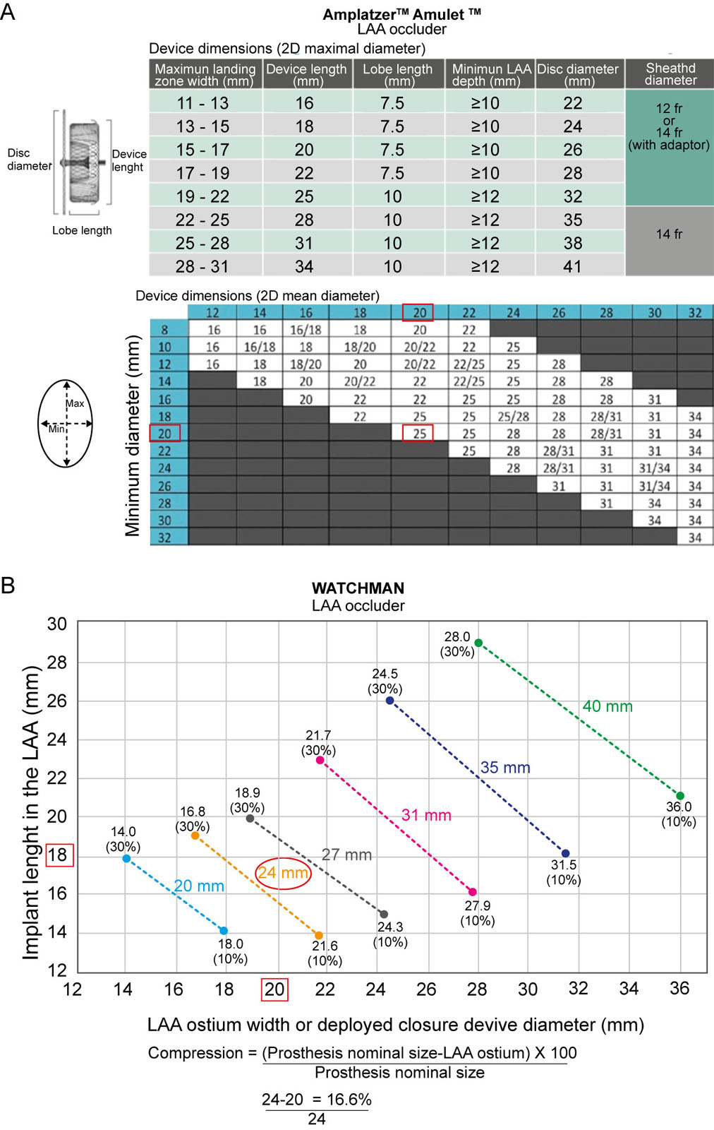
Selection of LAA device sizes. There are specific sizing charts for the Amulet and Watchman LAA occluder. (A) For the Amulet, if the landing zone maximal diameter is 20 mm, the device would be a 25 mm length (upper chart). However, if the maximal diameter is 20 mm but the minimal diameter is 18 mm, then select a 22 mm length (lower chart). (B) For the Watchman, if the LAA ostium width was 20 mm and the implant length was 18 mm, then select a FLX 24 mm device. The compression would be 24/20 with a 20% compression. A FLX 27mm would lead to a 27/20 35% compression. * The occluder nominal size are 20,24,27,31, 35 and 40. The dotted line corresponds to the 10% to 30% compression range. Abbreviations: 2D, two-dimensional; LAA, left atrial appendage; Min, minimum; Max, maximum. Adapted from Freixa et al.74
eFigure 33.32
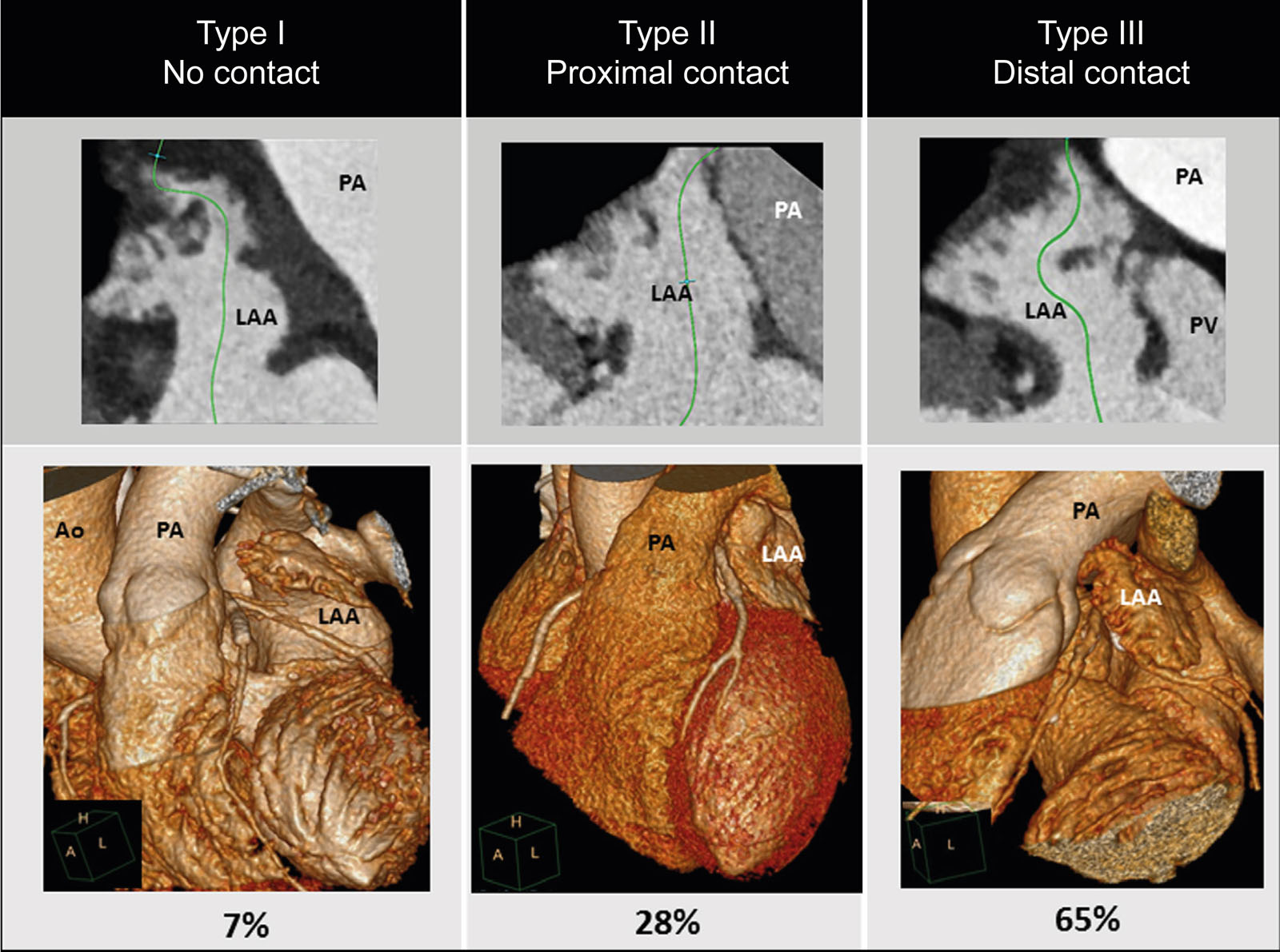
LAA-PA relationships. These 3D CT reconstructions and diagrams show the prevalence and types of anatomic relationships between the LAA and PA. Type 1 is complete separation between the LAA and the PA. Type 2 involves contact between the proximal PA and Type 3 is contact between the distal PA. The risk of perforation is greater with the Amulet. Abbreviations: Ao, aorta; CT, computed tomography; LAA, left atrial appendage; PA, pulmonary artery; PV; pulmonary vein. Source: Halkin A, et al.75
eFigure 33.48
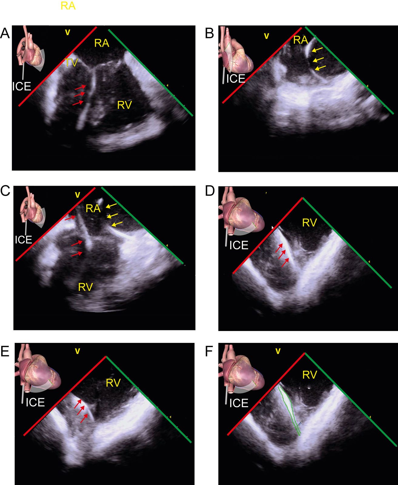
ICE clinical examples. These are ICE images in a patient with a dual-chamber pacemaker, including (A-C) ICE RA views showing the RV lead (red arrows) and RA lead (yellow arrows), and the (D,E) ICE RV views. (F) The leads can be “drawn” on the ICE image (green lines) and imported into the 3D navigation system to minimize the risk of lead dislodgement during catheter manipulation. Abbreviations: 3D, three-dimensional; ICE, intracardiac echocardiography; RA, right atrium; RV, right ventricle; TV, tricuspid valve.
Videos
Chapter 33 Fig02A
Chapter 33 Fig02B
Chapter 33 Fig03A
Chapter 33 Fig03CDEF
Chapter 33 Fig04A
Chapter 33 Fig04D
Chapter 33 Fig04E
Chapter 33 Fig05A
Chapter 33 Fig05B
Chapter 33 Fig05C
Chapter 33 Fig07A
Chapter 33 Fig07B
Chapter 33 Fig07C
Chapter 33 Fig09B
Chapter 33 Fig11A
Chapter 33 Fig11C
Chapter 33 Fig12ABCD
Chapter 33 Fig13A
Chapter 33 Fig13DEF
Chapter 33 Fig14A
Chapter 33 Fig14C
Chapter 33 Fig14D
Chapter 33 Fig14F
Chapter 33 Fig14G
Chapter 33 Fig14I
Chapter 33 Fig15AC
Chapter 33 Fig15D
Chapter 33 Fig16ABCD
Chapter 33 Fig17A
Chapter 33 Fig17C
Chapter 33 Fig17F
Chapter 33 Fig18A
Chapter 33 Fig18D
Chapter 33 Fig18F
Chapter 33 Fig19A
Chapter 33 Fig19CDEF
Chapter 33 Fig21A
Chapter 33 Fig22A
Chapter 33 Fig23ABCDEF
Chapter 33 Fig24A
Chapter 33 Fig25A
Chapter 33 Fig25E
Chapter 33 Fig25G
Chapter 33 Fig26F
Chapter 33 Fig29A
Chapter 33 Fig29B
Chapter 33 Fig30A
Chapter 33 Fig30B
Chapter 33 Fig30D
Chapter 33 Fig30E
Chapter 33 Fig31A
Chapter 33 Fig31C
Chapter 33 Fig31D
Chapter 33 Fig33A
Chapter 33 Fig33B
Chapter 33 Fig33D
Chapter 33 Fig34E
Chapter 33 Fig35
Chapter 33 Fig36B
Chapter 33 Fig36C
Chapter 33 Fig36F
Chapter 33 Fig36G
Chapter 33 Fig36H
Chapter 33 Fig37A
Chapter 33 Fig37B
Chapter 33 Fig37C
Chapter 33 Fig37D
Chapter 33 Fig38A
Chapter 33 Fig38B
Chapter 33 Fig38C
Chapter 33 Fig38D
Chapter 33 Fig39A
Chapter 33 Fig39BD
Chapter 33 Fig39C
Chapter 33 Fig40B
Chapter 33 Fig40D
Chapter 33 Fig41A
Chapter 33 Fig41B
Chapter 33 Fig41D
Chapter 33 Fig41E
Chapter 33 Fig41F
Chapter 33 Fig42BD
Chapter 33 Fig43A
Chapter 33 Fig43B
Chapter 33 Fig43C
Chapter 33 Fig43D
Chapter 33 Fig44C
Chapter 33 Fig44D
Chapter 33 Fig46B
Chapter 33 Fig46D
Chapter 33 Fig46E
Chapter 33 Fig46F
Chapter 33 Fig47A
Chapter 33 Fig47B
Chapter 33 Fig47D
Chapter 33 Fig47E
Chapter 33 Fig47G
Chapter 33 Fig50
Chapter 33 Fig51A
Chapter 33 Fig51B
Chapter 33 Fig51D
Tables
eTable 33.1 Closure device characteristics
| Device name | Design | Indicated use | Sizes (mm) | Regulatory status |
| Abbott Medical (Minneapolis, MN, USA) | ||||
| AMPLATZER® Septal Occluder (ASO) | Double flat disc, nitinol wire mesh, central waist 3-4 mm long, Polyester fabric inserts | Secundum ASD | 4–40 (central waist). Left disc is 12-14 mm larger than the waist and the right disc is 8-10 mm larger. | FDA CE mark |
| AMPLATZERTM Multi-fenestrated Septal Occluder “Cribiform” | Idem to ASO but short connecting waist (3 mm) | Fenestrated Secundum ASD | 18–25-30-35 (disc sizes). Both discs are equal. | FDA CE mark |
| AMPLATZERTM TalismanTM PFO Occluder | Idem to Multi-fenestrated | PFO | Right disc = 18–25-30-35 mm large Left disc = respectively 18, 18, 25 and 25 mm | FDA CE mark |
| AMPLATZERTM Muscular VSD occluder | Idem to ASO but 7 mm long waist | Muscular VSD | 4–18 mm central waist Discs are 8 mm larger than the waist except for the smaller size (5 mm larger) | FDA CE mark |
| AMPLATZERTM P.I. Muscular VSD occluder | Idem to Muscular VSD but longer waist (10 mm). filled with 3 polyester patches. | Post-infarction muscular VSD | 16–24 mm central waist Discs are 10 mm larger than waist | FDA CE mark |
| AMPLATZERTM Membranous VSD Occluder | Double flat disc | Membranous VSD | 4–18 mm | CE Mark |
| AMPLATZERTM Duct Occluder I | Cylindrical plug, flared collar | PDA | 5-16 mm (aorta side) 4–14 mm (PA side) | FDA CE mark |
| AMPLATZERTM Duct Occluder II | Cylindrical waist (4 or 6 mm long) with 2 retention discs | PDA | 3–6 mm Discs are 6 mm larger than waist | FDA CE mark |
| AMPLATZER PiccoloTM | Idem to Duct II | PDA (premature babies) | 3-5 mm discs are 1 to 1.5 mm larger than the waist | FDA CE Mark |
| AMPLATZERTM AmuletTM | Lobe connected to a disc by a short waist (dual occlusion mechanism) | Left Atrial Appendage (LAA) | 16-34 mm (lobe size) Disc on the ostium is 6-7 mm larger than the lobe. | FDA 2022 CE mark |
| AMPLATZERTM Vascular Plug II | Round device | Paravalvular leak (PVL) Vessels - Fistulas | Plugs diameter (3. 4, 6, 8, 10, 12, 14, 16, 18, 20 and 22 mm) | FDA CE Mark |
| AMPLATZERTM Vascular Plug III | Cylindrical device | Paravalvular leak (PVL) | Variable waist sizes (4x2 mm to 14x5 mm) Oval discs = 4 mm larger than the waist | CE Mark |
| AMPLATZERTM Vascular Plug IV | Conical device | Vessels - Fistulas | XXX | CE Mark |
| Boston Scientific (Marlborough, MA, USA) | ||||
| Watchman FLX PRO | Self-expanding nitinol frame fixation anchors partially covered by a permeable fabric cover. | LAA | 20 to 40 mm | FDA 2015 CE Mark 2005 |
| Cardia, Inc. (Eagan, MN, USA) | ||||
| Ultrasept ASD Closure Device | Dual articulating polyvinyl alcohol (PVA) umbrella sails 6-arm nitinol frame | ASD | 6-34 mm (centering mechanism) | CE Mark |
| Ultrasept PFO and Cribiform Closure Devices | PFO | 25-30-35 mm discs. 20 mm device also for PFO. | CE Mark | |
| Cardia Fenestrated Fontan Closure System | Fenestrated Fontan | 15- and 20-mm devices | CE Mark | |
| W.L. Gore & Associates, Inc. (Flagstaff, AZ, USA) | ||||
| GORE CARDIOFORM Septal Occluder | Circular shape helix made of ePTFE membrane. Nitinol circumferential single wire frame | PFOs Small secundum ASD (<17 mm) | 20-25-30 mm | FDA CE mark |
| GORE CARDIOFORM ASD Occluder | ASD up to 35 mm | Maximum outer disc = 27-32-37-44-48 mm | FDA CE mark | |
| Occlutech GmbH, (Jena, Germany) | ||||
| Figulla® Flex II Occluder | Conformable nitinol braiding with a biocompatible titanium oxide surface. PET patch (single or double LA layers) No hub on the left atrial disc. | PFO | Single LA Layer (RA 25 mm/ LA 23 mm) Double LA layers (RA/LA discs 18/18, 25/23, 30/27 and 35/31 mm) | CE mark |
| Figulla® ASD Occluder | Double flat disc of nitinol wire mesh, Spun-bonded PET-patch No hub on the left side | ASD | 4–40 mm waist Left disc = 7-15 mm larger Right disc = 5-10 mm larger | CE mark |
| UNI | Two discs of same size | Fenestration | 17, 24, 28.5, 33 and 40 mm | CE Mark |
| PDA Occluder | Cylindrical plug with flared collar | PDA | Diameters 3,5-14 mm. Long and standard shank lengths | CE Mark |
| PLD | Double disc device made from nitinol braided wires with two PET patches–one in each disc. | Paravalvular leaks | Central part = waist or twist Discs = rectangular or square | CE Mark |
| mVSD | Symmetrical discs | Membranous VSD | Waist = 4 x10 mm ad 20 x 28 mm Height = 7 mm | CE Mark |
| Atrial Flow Regulator (AFR) | Fenestrated device | Heart Failure PHT | Fenestration size 5 or 10 mm Waist length 8 or 10 mm Disc diameters 21 or 23 mm | CE Mark |
| Nobles Medical Technology (Fountain Valley, California, USA) | ||||
| NobleStitch | Percutaneous suture devices | PFO | CE mark US | |
| Cocoon Medical, UK | ||||
| Cocoon PFO and ASD Occluders | Platinum nanocoating on nitinol wire = inert, biocompatible, non-corrosive, non-allergic, more radio-opaque Discs filled with polypropylene fabric | PFO-ASD | 6 sizes for PFO (18/18, 25/18, 25/25, 30/25, 30/30 and 35/25 mm) | |
| Lifetech Medical, China | ||||
| Cera CeraFlex Lambre LAA Konar-MF VSD | PFO ASD VSD PDA LAA | |||
| Abbreviations: ASD, atrial septal defect; CE, European conformity; LA, left atrium; PET, Polyethylene terephthalate; PET, Polyethylene terephthalate; PFO, patent foramen ovale; PHT, pulmonary hypertension; RA, right atrium; VSD, ventricular septal defect. | ||||
| Amplatzer: https://www.cardiovascular.abbott/us/en/hcp/products/structural-heart/structural-interventions.html Boston Scientific: https://www.bostonscientific.com/en-US/products/laac-system/watchman-flx.html Cardia: https://www.cardiologic.co.uk/cardia-septal-occluders Gore: https://www.goremedical.com/products/cardioform/septal-occluder Occlutech: https://occlutech.com/ LifeTech: https://www.lifetechmed.com/en/ | ||||
eTable 33.7 Intracardiac echocardiography probes
| Features | VeriSight Pro (Philips) | NuVisionTM Biosense Webster (GE Healthcare) | AcuNav LumosTM (Siemens Healthineers) |
| Outer diameter | 9F | 10F | 12.5F |
| Minimum sheath size | 10F | 14F | |
| Working length (mm) | 900 | ||
| Articulating segment length (mm) | 75 | ||
| Fixed imaging distal tip length (mm) | 20 | ||
| Deflection controls | A-P R-L Lat | A-P Tip Rotation | |
| Deflection range (°) | -120° to +120° | -30° to +120° | |
| Broadband frequency range MHz | 4 – 10 MHz | ||
| Number of elements | 840 (15 x 56) | 840 (15 x 56) | |
| Field of view (°) | 90° | ||
| Volume field of view | 90° x 90° | 90° x 90° | 90° X 50° |
| Digital angle steering 2D imaging Biplane imaging 3D volume imaging 3D color flow imaging PWD - CWD Live multiplanar reconstruction | Yes | ||
| Abbreviations: 2D, two-dimensional; 3D, three-dimensional; CWD, continuous-wave Doppler; PWD, pulsed-wave Doppler. | |||
eTable 33.8 ICE views
|
ICE View | View-Technique | Utility |
1 |
 |
RA home view |
Chambers: RA, RV |
2 |
 |
RA home view with clockwise rotation |
Chambers: RA, RV, RVOT |
3 |
 |
RA view LVOT with further clockwise rotation |
Chambers: LV, LVOT |
4 |
 |
RA view LV with further clockwise rotation |
Chambers: LV, LA |
5 |
 |
RA view LA and LAA |
Chambers: LA, LV |
6 |
 |
RA view PV |
Chambers: LA |
7 |
 |
RA view aorta |
Chambers:, RA, LA |
8 |
 |
RA view esophagus |
Chambers: RA, LA |
9 |
 |
RA view IAS |
Chamber: RA |
10 |
 |
RA view IAS |
Chambers: RA |
11 |
 |
RV view |
Chambers: RA, RV |
12 |
 |
RV view |
Chambers: LV |
13 |
 |
RV view |
Chambers: LV |
14 |
 |
RV view |
Chambers:LV |
15 |
 |
RV view |
Chambers: LV, LVOT |
16 |
 |
RV view |
Chambers:, RA, LA |
17 |
 |
RV view |
Chambers: RVOT |
18 |
 |
LA view |
Chambers: LA |
19 |
 |
LA view |
Chambers: LA, LV |
20 |
 |
LAA view LA |
Chambers: LA |
21 |
 |
LAA view LUPV |
Chambers: LA |
22 |
 |
LAA view supra-mitral |
Chambers: LA |
23 |
 |
SVC view |
Chambers: RA, LA |
24 |
 |
SVC view |
Chambers: RA |
25 |
 |
SVC view |
Chambers: RA |
Abbreviations: AoV, aortic valve; Asc, ascending; CR, coumadin ridge; Des, descending; IAS, interatrial septum; ICE, intracardiac echocardiography; IVC, inferior vena cava; LA, left atrium; LAA, left atrial appendage; LCx, left circumflex artery; LLPV, left lower pulmonary vein; LMCA, left main coronary artery; LUPV, left upper pulmonary vein; LV, left ventricle; LVOT, left ventricular outflow tract; MPA, main pulmonary artery; MV, mitral valve; PV, pulmonic valve; RA, right atrium; RAA, right atrial appendage; RV, right ventricle; RVOT, right ventricular outflow tract; SVC, superior vena cava; TV, tricuspid valve. Adapted from Alkhouli71 and Tang et al.72 |
|||