Circuit Bending
Tickle the Clock
Finding the Clock Circuit in Toys
You will need:
- An electronic noise-making toy.
- Small screwdrivers.
- A fine-tip permanent marker.
- Optional: two test leads with alligator clips and a resistor in the range of 1kOhm – 4kOhm.
Hacking is a lot like hot-rodding your car: you don’t need to be able to build a car from scratch to swap in a 4-barrel carburetor, but it helps to know what a carburetor looks like before you get too creative with the wrench. We’ll use a simple but useful hack as a step toward identifying basic electronic components, and introduce some electronic axioms along the way.
How to Choose a Toy
As with the radio in our “laying of hands” experiments (chapter 12), select a toy that is expendable, not too tiny, and has a built-in speaker. A toy that makes sound is preferable to a mute one, and sampled sounds (like voices, animal sounds, or instruments) are more rewarding than simple beeps. The more buttons and switches the better, generally speaking. Keyboards are a gamble: some cheap Yamahas hack magnificently (the PSS-140 is especially satisfying), while others have curiously limited potential for interesting modification. Cheaper is better, especially for our first experiments—the more expensive toys, and almost all that put out video, often use crystal clocks, which are more difficult to hack (these include sophisticated handheld games such as Gameboys, robot toys such as Furbies, and more sophisticated music keyboards). However, since the start of the new millennium there has also been an increase in the number of super-cheap toys coming from China that are really impossible to hack (this will be explained), so beware. To the degree that one can distinguish such detail when trawling through thrift shops, toys from the 1990s hack more easily than more recent ones, and usually have a richer sound palette than most from the 1980s (with a few notable exceptions: the venerable “Speak and Spell”, introduced in 1978, is worshipped by circuit benders).
And: THE TOY MUST BE BATTERY POWERED!
Clocks
The majority of electronic toys manufactured since the early 1990s are essentially simple computers dedicated to running one program. In most, a crude clock circuit determines the pitch of the sounds and the speed of its blinking lights, graphics and/or program sequence.If you can locate the clock circuit and substitute one component, you can transform a monotonous bauble into an economical source of surprisingly malleable sound material.
What’s Under the Hood?
Open up the toy, carefully noting wire connections in case one breaks. Keep the batteries connected, as we did with the radio in chapter 12 (similarly, this might require some ingenuity, clip leads and electrical tape). Expose both sides of the circuit board.
Study the board and try to identify the following types of components:
- Resistors: little cylinders encircled by colorful 1960s retro stripes (see figure 1).
- Capacitors, in two basic forms (see figure 2):
- small discs of dull earth tones, or colorful squares;
- cylinders, upright or on their side, fatter than resistors, with one stripe at most.
- Transistors: three wire legs supporting a small black plastic blob or metal can (see figure 3).
- Diodes: glass or plastic cylinders, smaller and less colorful than resistors, usually marked with one stripe (see figure 4).
- Integrated Circuits (ICs): usually black or grey, resembling rectangular bugs with legs along one or more sides, or malignant looking black circular blobs oozing up from the circuit board (see figure 5).
- LEDs (Light Emitting Diodes): colorful sources of light (see figure 6).
- Other things you’ll learn about later.
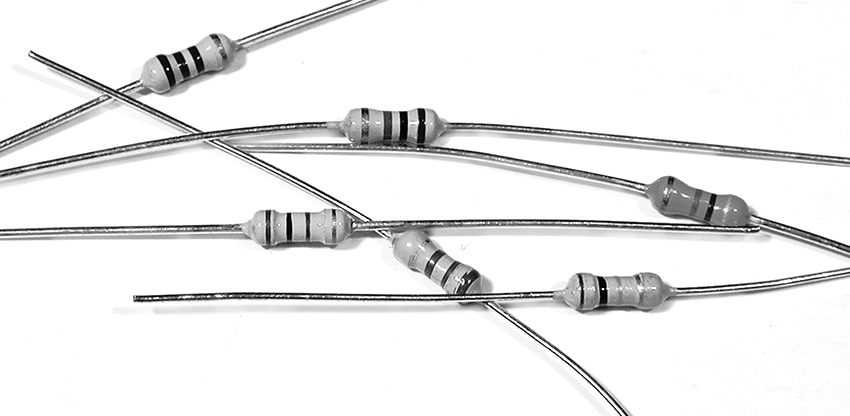
Figure 1 Some resistors.
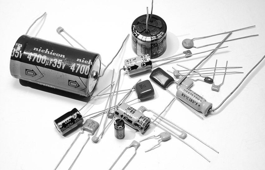
Figure 2 Some capacitors.
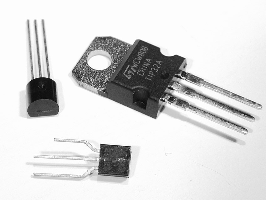
Figure 3 Some transistors.
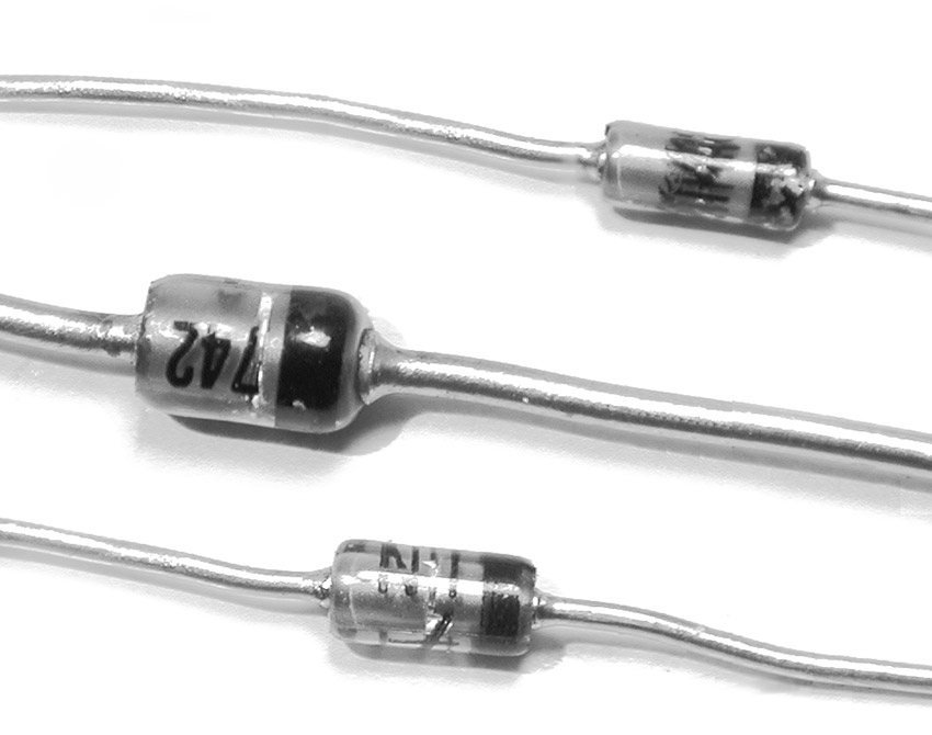
Figure 4 Some diodes.
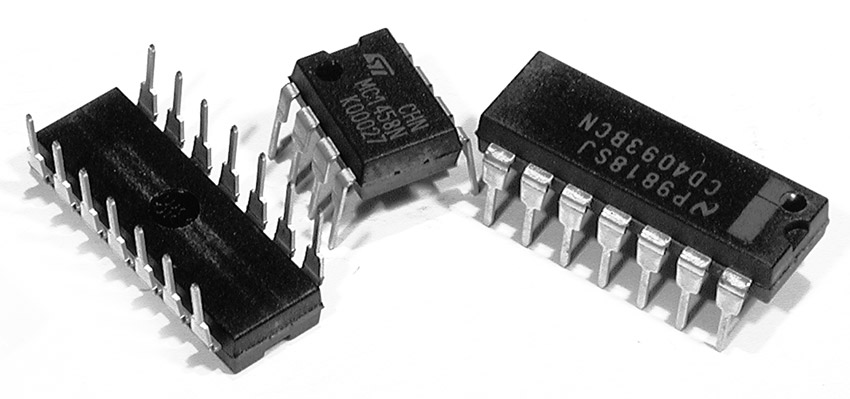
Figure 5a Some Integrated Circuits.
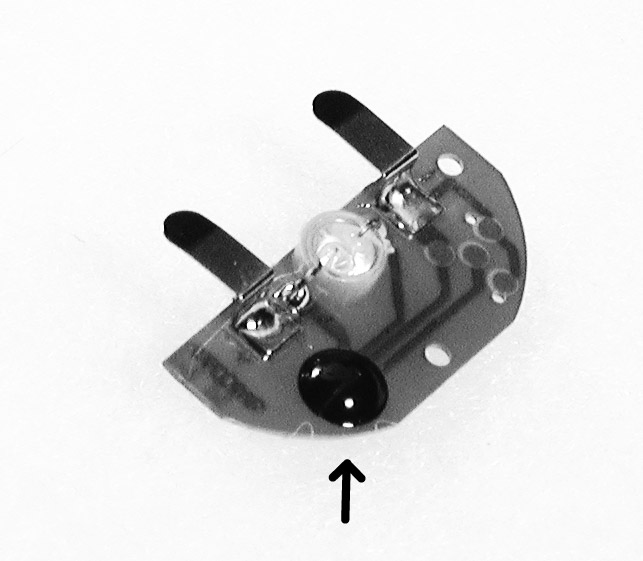
Figure 5b Some Integrated Circuits.
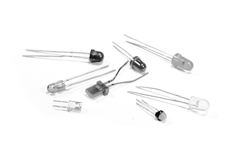
Figure 6 Some LEDs.
Most contemporary toys (as well as other electronic devics) are being made with “surface mount devices” (SMDs)— insanely tiny, rectangular versions of the above building blocks (see figure 7). Until you gain some hands-on experience with them you can despair of distinguishing the various different types of components, and decoding and hacking these toys will be a doubly foggy experience. If you have a choice, start your experiments on a toy with the larger, more traditional and more easily identifiable components described above (another reason to scavenge an older, used toy in a thrift shop, rather than buy something new at the mall).
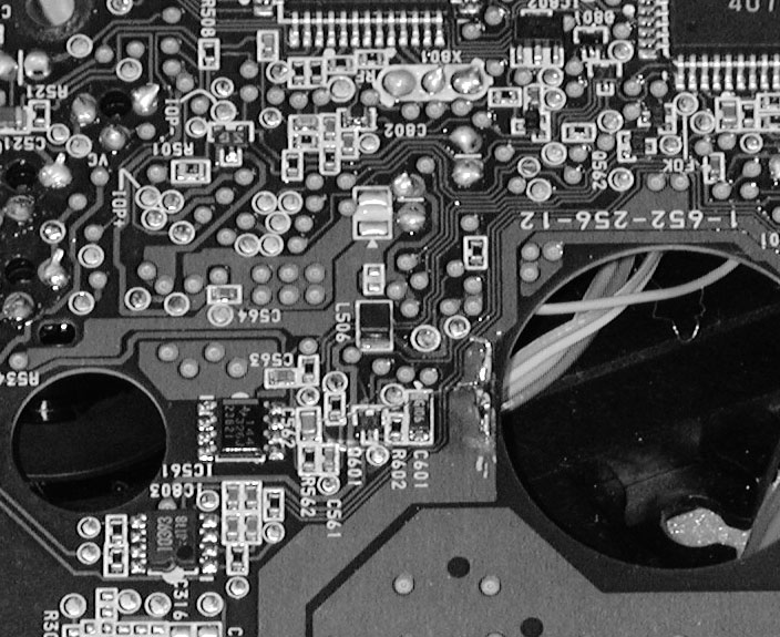
Figure 7 Circuit board with disturbingly small surface mount components.
We’re looking for resistors, especially those lying near an IC, flanked by a disc or square capacitor. The frequency of the simple, easily-hackable clocks in most toys is controlled by a resistor and a capacitor working together (explanation follows – be patient). If the circuit board appears to have one shiny black blob and not a single resistor, you may be holding one of the unhackable new Chinese toys: the clock is hidden inside that blob, where you can’t get at it, so you might as well hand the toy on to a grateful child and return to the thrift shop.
Laying of Hands, Again
As with the radio experiment we did in chapter 12, your fingers are usually the most direct form of circuit manipulation and testing. Get the circuit making sound. Position it so that you can touch the solder-side of the circuit board, if possible while looking at the component side. Lick one fingertip and place it across various solder pads; in particular try to connect across points at either end of a resistor, so that your finger parallels the resistor’s connection (see figure 8). When your finger bridges a resistor that is part of the clock circuit you should hear the pitch slide up a bit, or the tempo speed up. If the circuit has lots of connections, and you are having trouble finding the spot, concentrate on those resistors lying close by small capacitors, usually near the biggest IC on the board. If the circuit is too small for your fingers, clip a test lead to each end of a resistor in the range of 1–4kOhm, and touch the free ends of the leads to the ends of various resistors on the circuit board until you hear the pitch go up.
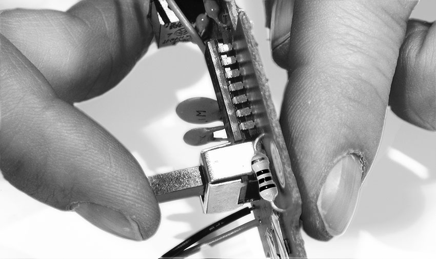
Figure 8 Finding the clock resistor (finger on right).
When you think you’ve found a hot spot, mark it on the circuit board with a Sharpie.
If the circuit incorporates the above-mentioned SMDs, most of the components and connections will be on the same side of the board, and it may be difficult to distinguish the capacitors from resistors. Sometimes resistors are identified by the letter “r” followed by a number, in a miniscule font, either on the component itself or (more likely) immediately adjacent to it on the circuit board; likewise capacitors are sometimes labeled with a “c” plus a number. Go after the blips with two shiny solder blobs at either end, rather than three or more, and you’re more likely to hit one of the timing components (your pinky may prove a more suitable tool than your index finger). Good luck—it can be very frustrating, and at a certain point you may want to give up, go out, and find yourself another (older) toy with bigger, more recognizable components.
If you have no success finding the spot, the toy might be one of the new, super cheap Chinese models described above. Or it may use a crystal for the clock timing, rather than a simple circuit with a resistor and capacitor (as mentioned earlier, this is especially true for more advanced musical keyboards, toys with video output, and complex or expensive toys). Crystals often take the form of a small shiny metal cylinder or a three-legged epoxy-dipped blob, usually brightly colored. If you suspect a crystal is at work you’d best put the toy aside and try another. On the other hand, sometimes you’ll get lucky and won’t even need to lay a finger on the circuit board to find the clock resistor: some toys, such as the “Microjammer” guitars, include a pitch control knob or slider.
What’s Happening?
Electric current flows through wire like water through a fat pipe. Resistors are like skinny pipes, or the rust-laden risers of NYC loft buildings: the higher the resistance (measured in chantworthy Ohms), the less current flows. Capacitors also resist the flow of electric current, but resist it more at some frequencies than others, in a manner that defies a simple liquid analogy. Capacitance is measured in soukable Farads, usually in small enough amounts to be called “microfarads” or “picofarads.” (Yes, the vocabulary of hardware is much cuter than that of software.)
Many oscillator designs rely on feedback: a speaker feeding back into a microphone is essentially an oscillator; when your damp finger bridges the right contacts on a radio circuit it produces feedback around an amplifier stage and sets the circuit oscillating. A clock circuit, whether in a cheap toy or an expensive computer, is just an oscillator, designed to run at a specific, carefully chosen frequency. In the simple clock circuit used in most toys a resistor and a capacitor are built into the feedback loop of a kind of an amplifier. With enough gain this circuit starts to feed back, just like a mike and speaker, at a frequency determined by the values of the resistor and capacitor. Make the resistor or capacitor smaller and the frequency goes up; make either larger and the frequency goes down. When the frequency gets too high to hear, it enters the range of a useful clock rate for a computer or a digital toy (or a way to summon your dog).
When you place one resistor in parallel with another you lower the overall resistance (think of it as adding an additional pipe for the current to flow through – see “Ohm’s Law” in the Technical Bootcamp section of this website).) Your skin is a resistor, as we demonstrated in chapter 12); when you press your finger across the circuit board contacts you effectively add a second pipe to the resistor on the other side of the board, decreasing the net resistance. More current flows and the pitch goes higher.
If the explanation is confusing, don’t worry about it. For better or for worse, we’ll revisit the secret lives of resistors and capacitors in a more clinical fashion when we get to building our own oscillators in Chapter 13. Until then just let your fingers do the thinking (and watch Video 13, “Hack The Clock”, in the Tutorials section of the website).
Got it? Good. But what do we do if we want to make the pitch lower? Read on….
Hack the Clock
Changing the Clock Speed for Cool New Noises
You will need:
- The sound-making electronic toy.
- Some hookup wire, stranded and solid, 22-24 gauge.
- Test leads with alligator clips.
- A few resistors of different values.
- A potentiometer, 1MΩ or greater in value.
- Soldering iron, solder, and hand tools.
Wet fingers are fine for making the clock go faster. But we all know that the Third Law of the Avant-Garde states:
Slow it down, a lot.
To slow it down we need to make the resistance larger instead of smaller. Which means removing the clock resistor from the circuit board (once you are sure which one it is) and replacing it with a larger one, instead of bridging it with your finger as we did in the last chapter which, by lowering the resistance, can only make the pitch go up.
- Locate the clock resistor you identified in the previous experiment (“Tickle the Clock”). Wedge a small flat-bladed screwdriver under it. Melt the solder on the underside of the circuit board at one end of the resistor, and lever the screwdriver to lift that end free from the solder connection (see figure 1). Do this quickly but gently, so as not to damage the circuit board or components. Now grip the resistor with a pair of pliers and pull it free of the board as you melt the other solder joint. Put it somewhere safe and don’t lose it! If the circuit already has a pitch-control potentiometer (“pot”), de-solder and remove it entirely.
- Strip and tin the ends of two short pieces of hookup wire. Press the end of one into one of the holes left after removing the resistor from the component side of the circuit board. It’s easier to do this with solid hookup wire, but in the long term it’s better if you use thin stranded wire for this, so you might want to give it a try (twist the stranded wire before tinning and it will be more likely to pass neatly into the hole). Melt the solder on the solder side of the board as you press the end of the wire through the hole. Touch up the solder joint with a bit of fresh solder to make sure it is solid, but avoid excess solder “bridging” the gap between traces that are supposed to be separate. Repeat with the second wire into the other hole. Your circuit board should now have two colorful whiskers sprouting from among the other, vertically challenged components (see figure 2). If you removed a pot from the board, there may be more than two holes; solder a wire to each of them. If you have problems fitting the wires through the holes you may have to clear out the old solder first – the best tool for this is the eerily cosmetological-looking “solder sucker” (see figure 11 in “Analog to Digital Conversion” on this website), but an artfully wielded straight pin can work too.
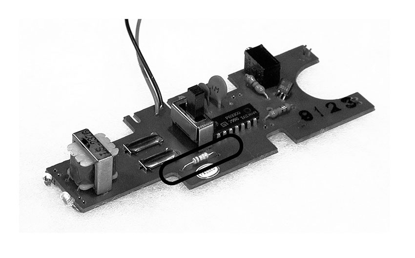
Figure 1 Removing a resistor.
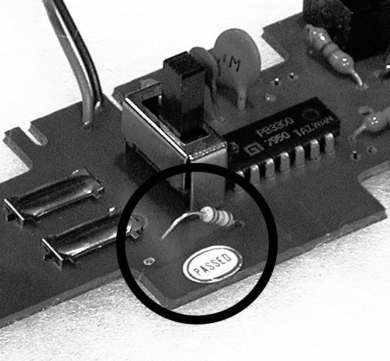
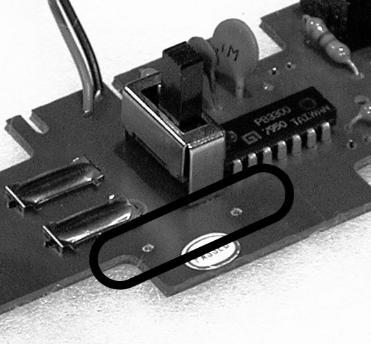
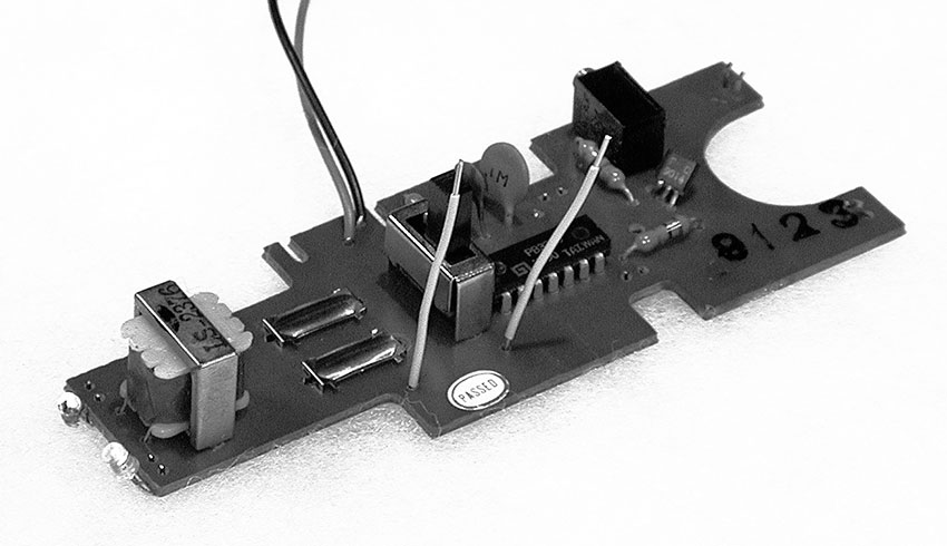
Figure 2 Resistor whiskers.
The copper traces on printed circuit boards can be very delicate, and the twisting of the wires as you go through the following experiments can tear the trace, sometimes irreparably. Which is why greater flexibility of stranded wire offsets the difficulty of forcing it though the holes. It is also a good idea to provide some kind of strain-relief for your whiskers. The easiest method is to bend them gently so they lie flat against the board, and then tape them down with electrical tape to prevent them from moving at the point they pass through the board (see figure 3).
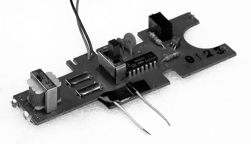
Figure 3 Whisker strain-relief.
- Attach a clip lead to the free end of each of the wires. Clip the resistor you removed between the other ends of the clip leads, effectively re-inserting it to the circuit (see figure 4). If you didn’t damage anything in de-soldering, the circuit should behave as it did before the operation. If it doesn’t, you may need to “restart” the toy by removing and reinstalling the batteries (see Rule #12, below).
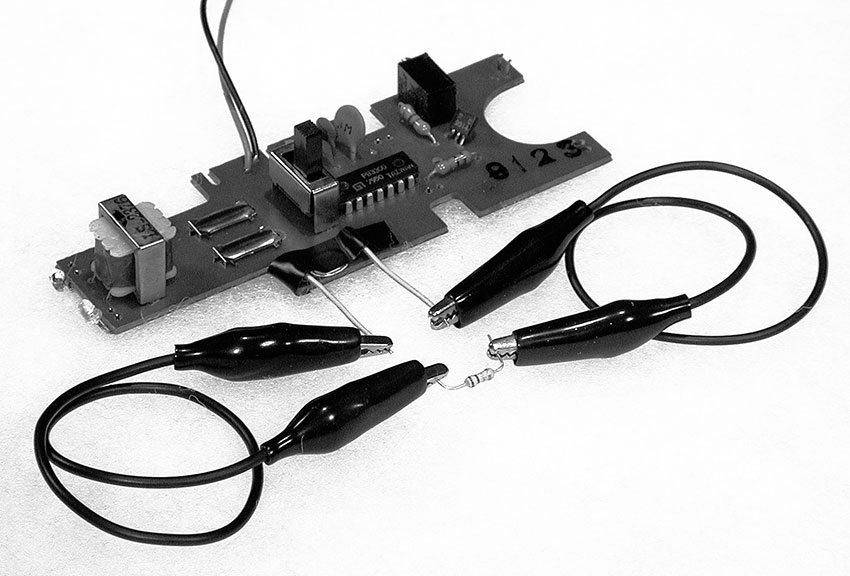
Figure 4 A remote resistor.
- Those colorful stripes around the resistor indicate its value. Look at the decoder chart in figure 5 below:
| Color | Value | Multiplier |
|---|---|---|
| Black | 0 | 1 |
| Brown | 1 | 10 |
| Red | 2 | 100 |
| Orange | 3 | 1,000 |
| Yellow | 4 | 10,000 |
| Green | 5 | 100,000 |
| Blue | 6 | 1,000,000 |
| Violet | 7 | 10,000,000 |
| Gray | 8 | 100,000,000 |
| White | 9 | 1,000,000,000 |
Figure 5 Resistor color codes.
Study your resistor. The first two stripes represent number values directly, the third is a multiplier, and a final gold or silver band the tolerance. So if the bands go: brown, black, yellow, silver:
Brown = 1
Black = 0
Yellow = multiply by 10,000
silver= +/–10 percent tolerance
So we get: 10 x 10,000=100,00 Ohms (or 100kΩ) +/–10 percent
Another example: orange (3) orange (3) red (x 100) gold = 3300 +/– 5 percent. Get it?
- What are the color bands of the resistor you removed?
What is its value? __________
- Go to your resistor assortment and find a resistor at least twice as big, and one about 1/2 the value. Clip the larger one into the circuit and the pitch should go down. Replace it with the smaller one and the pitch should go up. If either one does not work it may be so extreme a value that the circuit shuts down, so replace it with one whose value is somewhere between the original resistor and the non-functional one. In the event of such a crash, observe the 12th Rule of Hacking:
Rule #12: After a hacked circuit crashes you may need to disconnect and reconnect the batteries before it will run again.
(Count to five before replacing them.)
Substituting resistors should give you a good idea of what values produce what kind of sound, but you will probably want to vary the pitch/speed more fluidly. A potentiometer is a continuously variable resistor. In order to extend the pitch downward you need a pot whose maximum value is greater than the resistor you removed. Since most clock circuits use rather large resistors (100kΩ or larger) you will probably need a pot whose maximum value is 1megOhm (1,000,000Ω) or greater.
Pots have three terminals – two “ears” and one “nose” -- which are labeled A, B, and C in figure 6. The resistance between the outer two ears (A and C) is fixed at the designated value of the pot, which is the pot’s absolute maximum resistance (i.e., 1MΩ). As you rotate the shaft of the pot clockwise the resistance between the center terminal (nose) B and the outer terminal A goes up from 0 Ohms to the maximum value, while the resistance between B and the other outer terminal C goes down from the maximum to 0 — the two values change in contrary motion, like the ends of a seesaw. Reversing the pot’s rotation tips the seesaw back the other way.
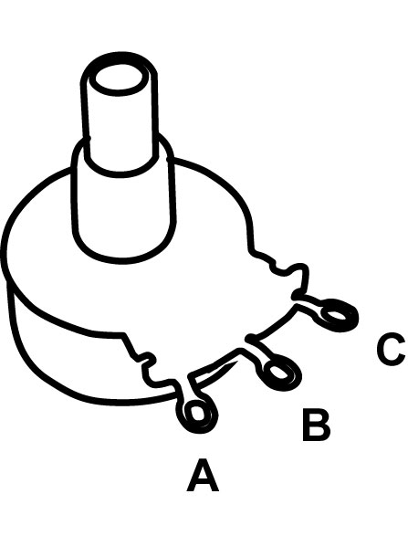
Figure 6 The three terminals of a potentiometer
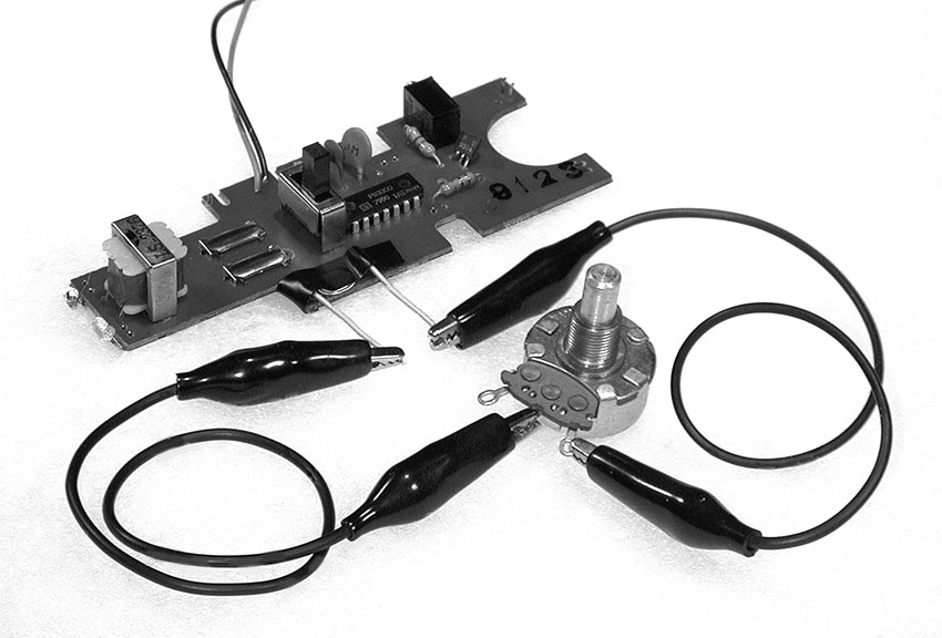
Figure 7 Pot substitute for a clock resistor.
Remove the resistor from the clip leads attached to the whiskers on your circuit board. Clip the free end of one of the leads to the center terminal (B) of your pot, and clip the other to the end terminal C (see figure 7). Rotate the pot and listen. The circuit will probably crash if you raise the pitch past a certain point and you’ll have to restart it (see Rule #12, above). But as long as you stay below that point in the pot’s rotation you should be able to coax a pretty wide range of sounds out of your circuit. If the toy appears to shut down when the clock is at its slowest, but restarts on its own when the pitch is raised again, the problem may be simply that the sound is going too low to be heard on the built-in speaker; try putting a telephone pickup on the speaker and amplify it through a bigger speaker. Of course you can always use the center terminal B and the other ear, A, but in this case the response of the pot will be backwards: the pitch will go down as you turn it further clockwise, rather than up. Which is fine, except slightly counterintuitive if you have worked with most commercial electronic music devices – there’s no time like now to start a revolution (or at least change its direction).
If there is no appreciable change in pitch or tempo you may have picked the wrong resistor as the clock timing component. Solder it back into the board and start over at step 1 probing for the hot spot with your wet finger. Other common causes of failure include torn traces (as mentioned in step 2 above), or sloppy soldering accidentally joining points on the circuit board that should remain separated.
If you removed a pitch-varying pot (instead of a fixed resistor) from the circuit you will have to experiment with connecting the terminals of your new pot to various combinations of leads from the circuit board before you find the correct hookup -- you can start by matching up the nose and ears of your replacement pot with those of the original part in the toy. Substituting a pot of larger value than the built-in one should give you a wider range of pitch/speed variation.
In case you were wondering, yes, you could also change the clock frequency by varying the capacitor in the clock circuit, rather than the resistor. But it is difficult to make a capacitor continuously variable over a wide range, and therefore this is a less practical approach to the problem of “playing” the clock. In chapter 13 we will substitute different size capacitors to set the frequency range of an oscillator, while a resistance is varied for continuous pitch change, but for now we’ll limit ourselves to experiments with resistors of various kinds.
Beyond the Pot
Photoresistors, Pressure Pads and Other Ways to Play Your Toy
You will need:
- Electronic toys and radios from the previous experiments.
- Some hookup wire.
- Test leads with alligator clips.
- An assortment of resistors and pots.
- A few different photoresistors.
- A flashlight.
- A soda straw (opaque if possible), or a short piece of heat shrink tubing.
- Some loose change.
- Anti-static foam from packaging Integrated Circuits.
- A small sheet of corroded conductive metal, such as iron, copper, or aluminum.
- A lead from a mechanical pencil.
- Some paper and a soft pencil.
- Some fruit and or/vegetables.
- A telephone pickup coil and small amplifier.
- A multimeter.
- Soldering iron, solder, and hand tools.
You’ve opened a toy, tickled the clock, replaced its timing resistor with a potentiometer, and learned a bit of theory about swapping resistors—what’s next in the way of toy hacks?
Photoresistors
A photoresistor (or photocell, as it is sometimes called) is a device that changes its value in response to light level: the resistance gets smaller when it is exposed to a bright light, and gets larger in the dark. It is small disk, whose diameter can range from 1/8” - 1”; two wires come out of one side, and the other side displays a pleasing zigzag pattern of fine lines (see figure 1). The side with lines is more sensitive to light than the other, but the back is translucent enough that light striking the back will affect the resistance as well. The lowest resistance in bright light is anywhere from 100 to 2000 Ohms, depending on the kind of photoresistor; the “dark resistance” is very large, typically around 10 megOhms. Because this is higher than most pots, and because most clock circuits use pretty large resistors, photoresistors are a convenient variable resistor for slowing down toys a lot.
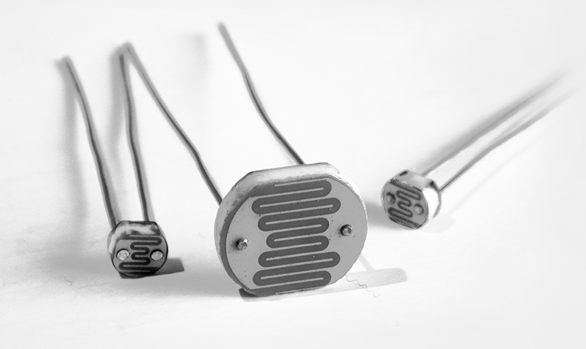
Figure 1 Some photoresistors
Photoresistors are pretty cheap. Some retail sources provide data on the range of resistance, sometimes not. In addition to different “light” (minimum) and “dark” (maximum) resistances, different photoresistors will respond at different speeds to changes in light level—some are more sluggish than others. All these factors affect how they perform in a musical circuit. You can test them with a multimeter, but ultimately your ear is the best guide to picking a good photoresistor for your circuit. Don’t be disappointed if it takes a while to find the perfect one.
Select a photoresistor. Remove the pot from the clock circuit of a toy. Using clip leads, attach the two leads of the photoresistor where the pot tabs were connected, or solder it directly in to the holes left when you removed the resistor (see figure 2). Turn on the toy and listen to how the circuit behaves when you pass your hand over the photoresistor or shine a flashlight on it. If you have more than one type of photoresistor swap them in and out, and listen to how different ones affect the circuit.
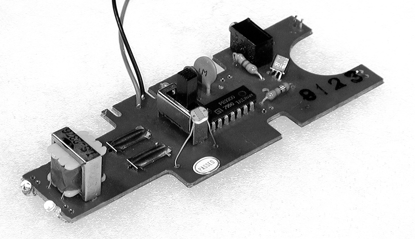
Figure 2 Photoresistor in place of a clock resistor
For maximum resistive range you must go from totally black (no light at all) to high illumination – carry your circuit into a closet and play it with a flashlight. More practically, you can mount the photoresistor at one end of an opaque tube (such as a drinking straw painted black, or a short piece of heat shrink tubing) to make it very directional in its light sensitivity: it will only respond to light aimed directly down the tube (see figure 3). This is the core technology of certain carnival shooting galleries, where each “gun” fires a light towards similarly blinkered targets.
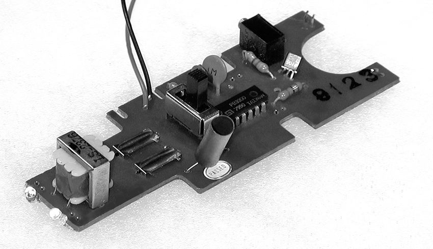
Figure 3 A shy photoresistor hiding inside a section of heat-shrink tubing.
You can put the photoresistor in your mouth and make a very expressive controller that responds to changes in both the light level as you open and close your mouth, and in the conductivity of your saliva-laden tongue across the photoresistor’s bare legs (a suggestively naughty extension of the licked-finger-on-circuit-board effect).
DON’T EVER THINK OF TRYING THIS WITH ANY CIRCUIT THAT IS EVEN BATTING ITS EYELASHES AT A WALL OUTLET!
Place a fan between a light source (such as flashlight) and the photoresistor, or reflect light off a record turntable (put some delicately crumpled aluminum foil on the turntable instead of a record)—you should hear a vibrato effect or other wobbly modulation, which changes as you vary the speed of the fan or turntable.
If the toy has blinking lights or LEDs you can tape the photoresistor against one of the lights and the toy will modulate itself, producing possibly interesting patterns. Two toys with blinking lights and photoresistor-controlled clocks can modulate each other—curiously erotic electronics! The more toys, the greater your chances of creating artificial life.
A photoresistor can be a good compromise between the fluid, if somewhat unpredictable (and occasionally dangerous), effect of the finger on the circuit board and the more controllable but less expressive potentiometer. You can use it as a very responsive performance interface to interpret hand shadows or flashlight movement, or as an installation sensor, reacting to ambient light and the shadows cast by visitors. We’ll look at more photoresistor applications in chapters 13 and beyond.
As I mentioned earlier, although the zigzagged side is more sensitive to light than the backing, most photo-resistors are made of translucent material, so that light striking the back will affect its resistance as well. It is important to cover the back if you want the greatest range. Besides burying the photoresistor in an opaque straw, you can seal off the back with black paint or electrical tape.
If you want to both the gestural quality of the photoresistor and the controllability of the pot, you can combine the two: if you wire a pot in series with a photoresistors (see figure 4), the pot will determine the maximum frequency of the clock in full light, and darkness will cause the speed to go down from that maximum. If you wire the pot in parallel with the photoresistor (see figure 5), the pot will set the minimum frequency of the clock in full darkness, from which the speed will go up as light increases. (If this sounds confusing, just try it).
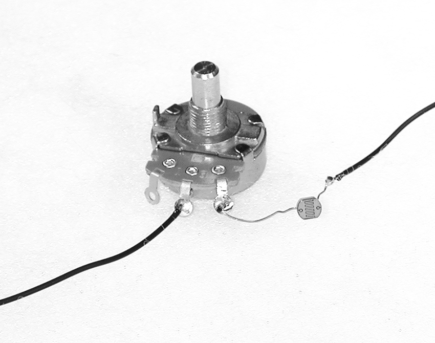
Figure 4 A potentiometer and photoresistor in series.
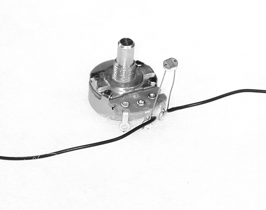
Figure 5 A potentiometer and photoresistor in parallel.
In total darkness, the photoresistor has a very large resistance—as high as 20mOhm— much higher than any commonly available pot. If you want really low frequencies out of your toy a photoresistor is the way to go – moreover, multiple Photoresistors can be strung together in series to drive a clock down into the glacially slow range.
Electrodes
Let’s not forget the heady spontaneity of our youthful experiments with flesh-controlled circuitry back in chapter 12. If you want to use your fingers to connect points on the board that are widely separated, or you just want a more formal playing surface, dimes or other silver-plated coins make excellent electrodes (copper tarnishes too quickly in an urban or coastal environment—just take a look at the Statue of Liberty). Strip 1/4 inch of insulation off both ends of a few 5 inches pieces of wire. Solder one end of each wire to one of the “sensitive points” you’ve found on the circuit board, and solder the other end to a coin. Arrange the coins in a pattern that lets you bridge them easily with your fingers, but avoid direct shorts (see figure 6). By the way, I was told as a child that it is illegal to solder or similarly deface U.S. currency, so you might refrain from performing on this one in the presence of the Secretary of the Treasury.

Figure 6a Coin electrodes and their use in performance.
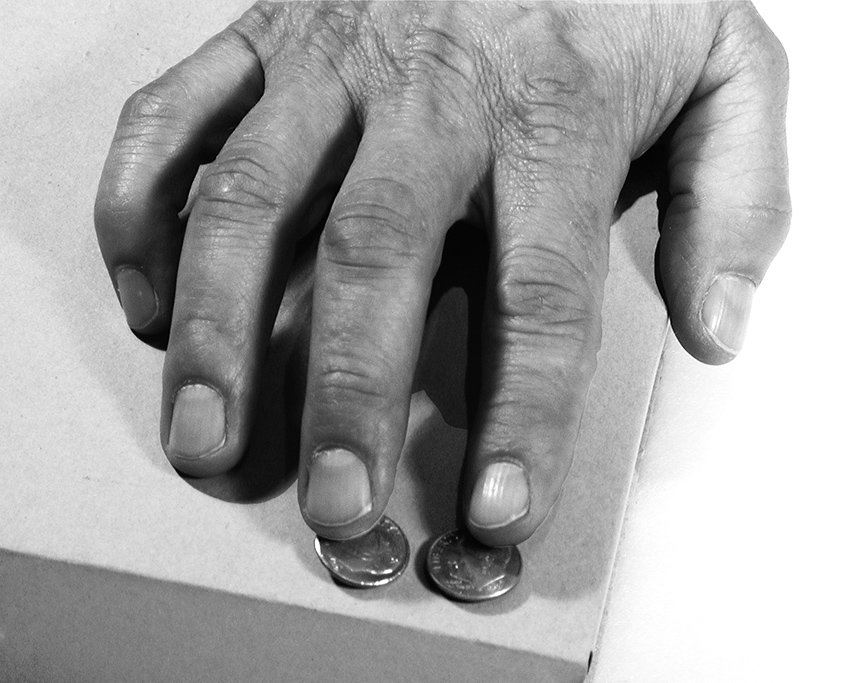
Figure 6b Coin electrodes and their use in performance.
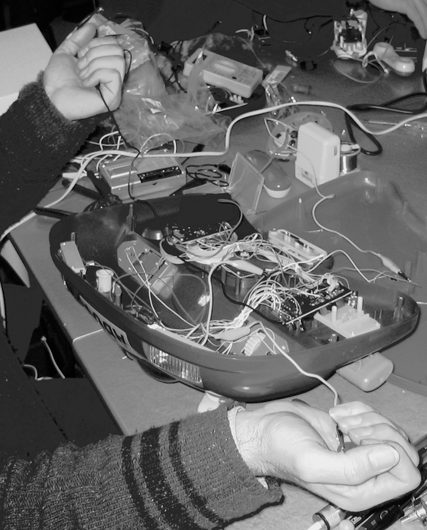
Figure 6c Coin electrodes and their use in performance.
A nice way to combine the control certainty of a potentiometer with the gestural possibilities of finger-on-circuitry is to parallel the pot and a pair of electrodes, as we did with the photoresistor in figure 5. When you solder your hook-up wires to the lugs of the pot leave an extra inch of bare wire sticking up through the solder hole. When you go to mount the pot in the box that will hold the circuit , drill small holes to line up with the wire ends and two more about 1/2 inch away. Lead the bare wires up through the panel at the pot and then down again, so that they form two parallel strips (see figure 7). You will have convenient electrode contacts immediately adjacent to the knob so you can slip your finger back and forth between precision adjustment and touchy-feely playing (you could also solder coins to these wires for a larger playing surface).
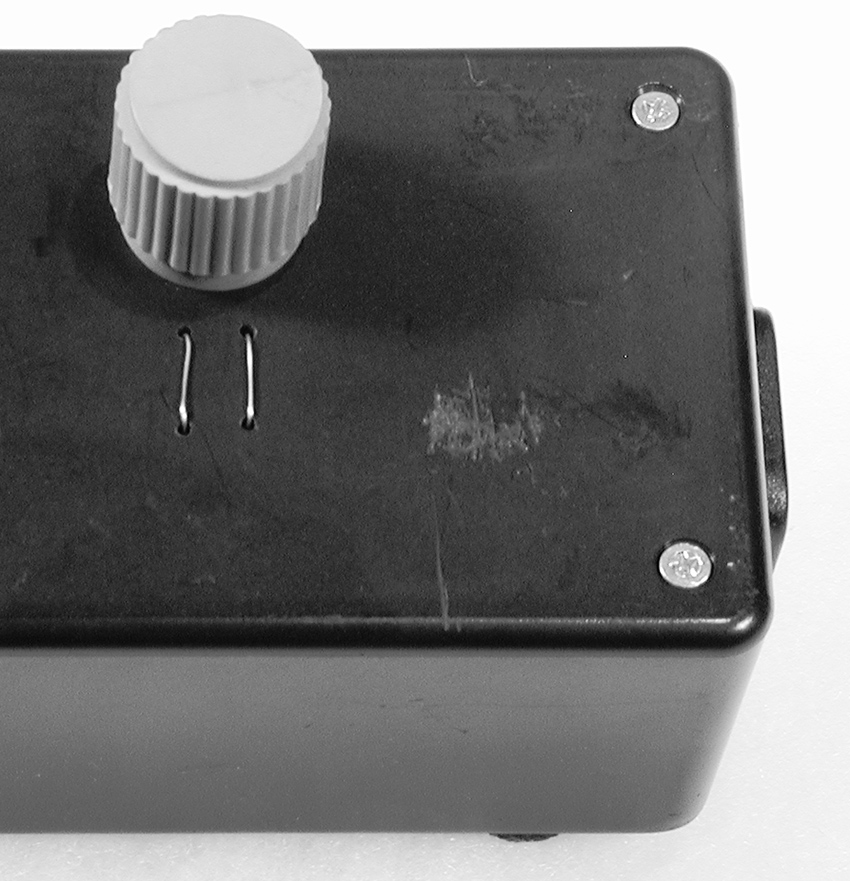
Figure 7 A potentiometer with electrodes in parallel.
Cheap Pressure Sensors
The squashy black “antistatic foam” in which Integrated Circuits are sometimes packaged has interesting electrical properties. Put a piece between two coin-electrodes and measure the resistance with a multimeter as you squeeze them together—it gets lower as you apply more pressure (see figure 8). This homemade pressure sensor can be used in place of a pot or photoresistor to make a pressure-sensitive controller for performance or installation (under chair legs to measure weight, for example). Antistatic foam can be bought in sheets from various online retailers, if you can’t find an engineer’s garbage pail from which to scrounge.
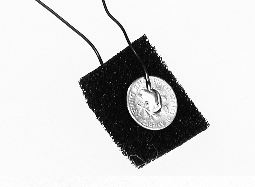
Figure 8 Pressure sensor made from anti-static foam and two coins.
Vegetables and fruit also have resistive value. This value changes as they dry out or are squished. You can substitute small slices of produce for the antistatic foam in the above experiment, or poke bare wires directly into carrots or apples. (As some of you may remember from childhood science experiments, it is also possible to make a battery out of fruit or vegetable – see “Power Supplies” inn the Technical Bootcamp section of this website).
Arty
A pencil lead from a mechanical pencil makes an excellent, if delicate, resistor (see figure 9). Attach two clip leads to the clock resistor contact points in your toy. Clip one wire to one end of the pencil lead, and scrape the jaws of the other along the lead. Resistance is proportional to the distance separating the contact points, so the pitch of the toy should go down as you move the clip further from the end. (Most potentiometers are simply a neatly packaged strip of carbon with a moving wiper.)
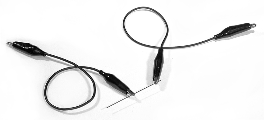
Figure 9 A pencil-lead resistor.
The use of graphite as a resistor is not limited to pencil leads themselves. Draw two blots near the edge of a piece of paper, and clamp the jaw of a clip lead to the paper at each blot; clip the other ends of the leads to the clock resistor contact points in your toy (see figure 10). Draw a line between the two blots and get the toy running—as you widen the pencil line linking the blots, or draw additional lines, the pitch should go up. Why? The wider the graphite path between the clips the lower the resistance (think fat pipes versus skinny pipes.) Patrick McCarthy has made functional rotary potentiometers using this technique (see his video in the “Circuits” section of the Gallery on this website).
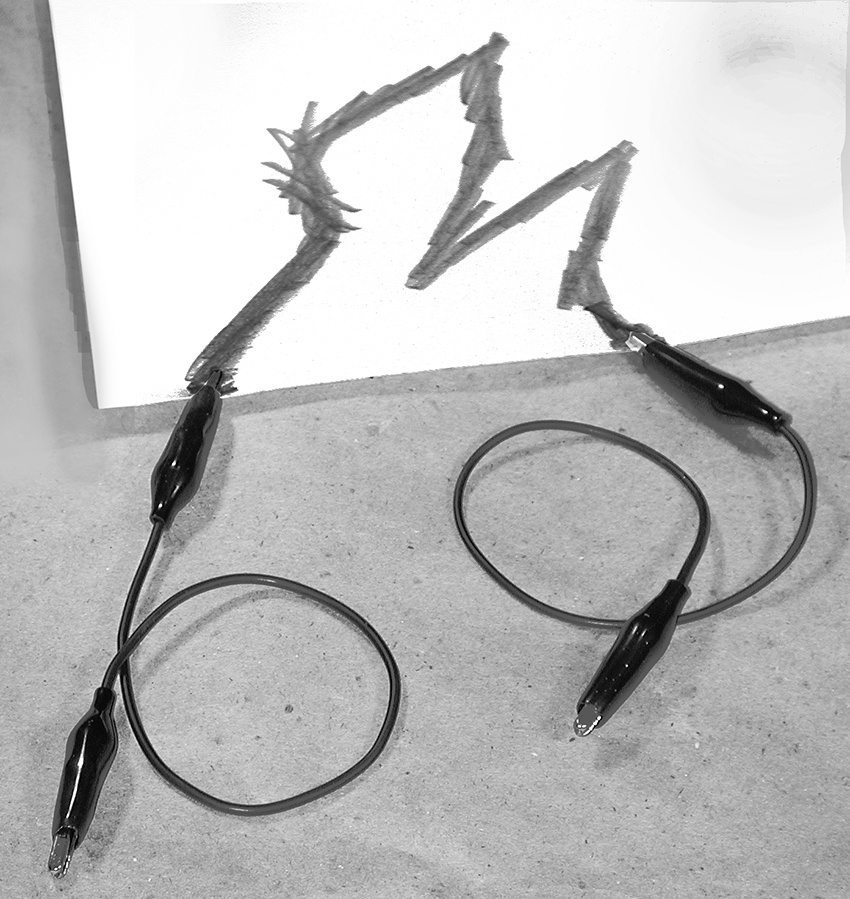
Figure 10 Drawing a resistor.
You can also use a strip of magnetic tape as an open-air resistor (old VHS tape works great): use two probes pressed against the surface, or an alligator clip at one end and one movable probe. As with the pencil line, resistance is proportional to distance. T. Escobedo’s “Synthstick” is a glissando-based instrument, sort of a cross between a Theremin and a Stylophone, based on this principle.
Almost a Short Circuit
Enough of clocks! Sometimes a toy can be induced to make curious sounds if you make new connections between various locations on the circuit board. Take a resistor in the range of 10-100 Ohms and bend it into the shape of a croquet wicket. While listening to the toy, press one end of the resistor to a solder point on the solder side of the board; then touch the other end to various other points—if the circuit board is large you may need to use a clip lead to reach all over (see figure 11). You may (or may not) get some interesting sounding circuit malfunctions. Disconnect immediately any connection that seems to cause heat, smoke, or flame.
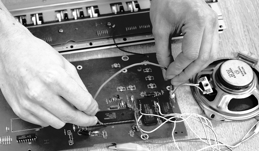
Figure 11 Phil Archer bridging the circuit board. Photo © Phil Archer, used by permission.
Try different value resistors but avoid shorting out the board with straight wire unless it’s the only thing that works (see the 7th Rule of Hacking). If you find that the best sounds happen with the smallest value resistor, you can try a straight wire, but do so gingerly and be prepared to remove the wire as soon as you feel or smell trouble. You can also try using pots or capacitors instead of resistors. You can go back to your radio and experiment with using resistors to jump between the hot spots you bridged with your damp finger.
Once you find a useful connection you can solder the resistor permanently into place, or add a switch to connect and disconnect it as a performable change (see next chapter for switch information).
This technique is the heart of Reed Ghazala’s wonderful Circuit Bending philosophy of hardware hacking, and is a very powerful and creative tool for extracting unusual sounds from almost any found circuit (see “Circuit Bending” essay on this website).
If you’re feeling suicidal, you can follow Phil Archer’s lead and dribble water on the circuit board – watch his video in the Circuit Bending section of the Gallery on this website, and watch out!
Rusty
A corroded metal plate and a nail can serve as a quasi-random variable resistor, as we demonstrated with the jumping speaker in chapter 3. Choose any two points on the circuit board that produce a change when they are connected to one another—this could be the clock resistor solder pads, or any of the hot spots we’ve just described bridging with resistors. Solder a short wire to each point, long enough to be grasped in the jaws of a clip lead. Clip the other end of one of the leads to a nail and the other lead to a sheet of rough or corroded metal (copper flashing, rusty baking sheet, file, etc.). Lightly scrape the nail across the metal and listen to the circuit twitter—the corrosion and intermittent hop, skip, and jump of the nail over the rough micro topography yields an ever-fluctuating resistance that can be steered (if not exactly controlled) by adjusting the pressure and speed of movement.
Motor-Mouth
Noise, flashing lights, and frenetic activity—the essential attributes of any disaster are also the core components of a successful toy. After messing around with the sounds and lights, don’t forget the motors that make tickled Elmo twitch and Billy Bass flap his tail. Some pretty sophisticate computer code goes into this electromagnetic choreography, and you can eavesdrop on it by placing a telephone tap coil on a motor and connecting the coil to your amplifier. There is often a beautiful rhythmic interplay between the toy’s sounds, blinking lights and movements, and a thorough hack can bring all this futurist polyphony to the ear. And don’t forget to try another coil on the toy’s speaker to make the basic sounds louder and wider range (as we did with the radio in chapter 12).
Interconnecting Toys
Once you’ve opened and hacked a few toys don’t be afraid to experiment with interconnecting them. First connect a clip lead between the grounds (“–” end of the batteries) of both toys. Then use another clip lead to make random connections between any point on one toy and any on the other. Use a jumper between the clocks and you may get the toys to cross modulate each other; if you connect clock points between two circuits and remove the resistor from one, you can sometimes drive both in sync from a single clock.
Remember that you can also link circuits through blinking lights and photoresistors, as described earlier in this chapter.
Lest you get too distracted by the gizmo-factor of all these add-ons, don’t forget the humble laying of hands. On larger circuit boards with multiple components (such as musical keyboards) a few damp fingers brushed against the circuit board can raise delightful havoc with the normal behavior of the toy—the Yamaha PS-140 is especially susceptible to fleshly corruption (see figure 12). British bending iconoclast Dan Wilson lets worms crawl across his circuit boards (see his video in the “Laying of Hands” section of the Gallery on this website).

Figure 12 Mike Challis playing his hacked Yamaha PS-140 by touching the circuit board through a hole cut through the case.
Beyond Toys
Most of the techniques described in this chapter can be used to extend the radio you opened up in chapter 12 as well: electrodes can be used to pull the radio’s ticklish spots to the outside of a box, and make it easier to bridge multiple points with your fingers; pots, photoresistors, pressure pads, resistors, and rusty nails can be used to link these points as well. Toys and radios are cheap and plentiful, and thus an obvious flashpoint for hacking insurgency, but the same methods can be applied to almost any electronic circuit: CD players (see figure 13), rock effect pedals (“stomp boxes”) (see figure 14), cassette players, answering machines—you’ll never know until you try them. Vic Rawlings (US) uses wire brushes, nails, fingers and assorted metal junk to play a complicated array of effect pedals – see his video in the “Laying of Hands” section of the Gallery on this website and figure 15. Neal Spowage (UK) has hacked metal detectors to make his “Electro Magnetic Wands” (see his video in the “Coil Pickups” section of the Gallery on this website).
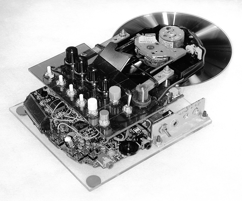
Figure 13 “Sled Dog” hand-scratchable hacked CD player (Nicolas Collins).
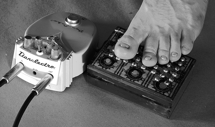
Figure 14 Hacked guitar effect pedal with electrode contacts for toes, Chris Powers.
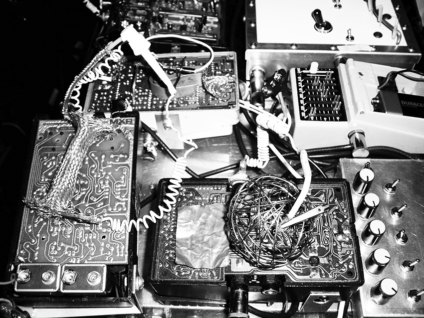
Figure 15 Performance setup showing open effect pedals with wire ball, Vic Rawlings. Photo © Vic Rawlings, used by permission
You can buy dozens of different kinds of electronic kits, from strobe lights to wind chimes, from online retailers and experiment with these kinds of modifications as you build them—hacking goes faster if you don’t have to disassemble first. After savoring bespoke electronics you’ll never accept off-the-rack again.
Video Music/Music Video
Translating Video Signals into Sound, Hacking Cameras, and Extracting Sounds from Remote Controls
You will need:
- A video camera or camcorder (it will not be destroyed).
- A video monitor.
- A cheap, hackable CCD video camera circuit board.
- Some phototransistors.
- Some photoresistors.
- A 74C14 Hex Schmitt Trigger.
- A CD3093 Quad NAND Gate.
- An infrared remote control from a TV or other appliance.
- An audio amplifier.
- Some raw speakers of various sizes.
- Some small mirrors, a laser pointer or flashlight.
- A piezo disk.
- Optional: surplus barcode reader
Various ingenious software tools exist for translating pictorial data into sound and vice versa: Soundhack’s “Open Any…” turns any computer file into a sound file (i.e., a Photoshop-to-hit-record converter), STEIM’s “Big Eye,” and Max’s “Jitter” track moving objects in a video image and extract MIDI or audio information. Chapter 22 details a number of circuits for video hacking. But here are a few super-simple hacks to get you started.
Light and Shadow
Several artists have translated images directly to sound by placing photoresistors on video monitors or projection screens (see “Visual Music” on this website). Wire up a few photoresistor-controlled oscillators (see chapter 13), using long sections of stranded wire to connect the photoresistors to the circuit board. Place the sensitive side of a photoresistor against the screen of a video monitor and use a thin strip of opaque electrical tape across the back to hold it in place; repeat for each photoresistor, distributing them across the screen. Connect a camera or other video source to the monitor and listen as you sweep the camera across the room or play back a tape. Action! Instant soundtrack! You can do this on a projection screen as well: -- the effect is stronger with film projection than video because of the increased contrast between light and dark. LCD screens on laptops work but have considerably less contrast. In brightness, so the pitch changes will be less dramatic.
You can also use the photoresistors to adjust the loudness of any audio signal (CD, computer, microphone, etc.) in response to fluctuations in the image, by adapting the gating and panning circuits from chapter 17 to work with photoresistors affixed to a monitor or projection screen. You can adapt the Theremin circuit in chapter 15 (figure 15.9) for video response as well – using the image to control both pitch and volume of multiple oscillators gives the resultant texture considerably more variety.
Frame Rate Music
We can also listen directly to a video signal itself. Use a Y-cord to split the analog video output of a camera. Connect one leg of the Y to a video monitor and the other to an amplifier and speaker—that’s right: the video output to the audio input. As luck would have it, a camera puts out a video signal that is approximately the same amplitude as a line-level signal from a CD, etc. Pan the camera around the room as you listen. You should hear a steady drone whose overtones fluctuate in response to the image content and brightness. The fundamental pitch is a function of the video frame rate (between B flat and B natural with NTSC video, between G and G# with PAL, and therefore unwavering if the camera is functioning normally, while the overtone balance directly represents the image data, line by line. Very nice, if you like drones.
Aim the camera through a rotating fan; vary the fan speed and you should hear interference patterns between the frame rate and the fan speed. Focus on a white card off-center on a black turntable mat, and switch the speed between 33 1/3 and 45rpm. Aim the camera at the monitor and look and listen as you experiment with video feedback. A video mixer, keyer, or special effects box introduces audible artifacts as well as visible ones. With a Y-chord splitter you can see and hear the effects – this is a technique used by several experimental VJs and video artists, including Jon Satrom, Billy Roisz and LoVid (see “Visual Music”). Aim an IR remote at the camera (most video cameras detect infrared light and display it as hot white) and listen to the burst pattern of the encoded data (see Channel Surfing Music below).
You can similarly listen to the video output of your DVD player - fanning it will have no effect, but it’s an easy way to generate an automatic soundtrack.
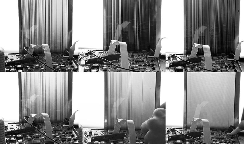
The frame rate is fixed, and normally doesn’t budge unless you move between NTSC and PAL. But if you invest in a cheap black and white CCD camera circuit board (scrounged from a surveillance camera, or available from most electronic surplus outlets for a modest price), you can experiment with tickling the clock frequency by a laying of hands (as we did in chapters 12) or replace the clock crystal with a variable oscillator (as discussed in chapter 15). The crystal is usually pretty conspicuous on the circuit board—often a metallic silver small cylinder or block (see figure 1).
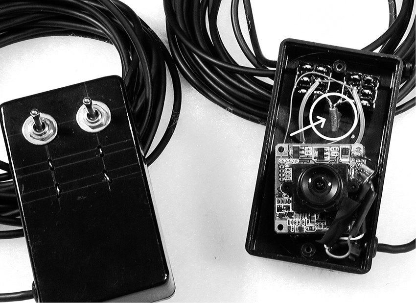
Figure 1 Crystal removed from hacked surveillance camera.
Split the camera output between a video monitor and amplifier using a Y-cord as before, so you can see as well as hear the effect of your hack. The video image produced by a tickled camera is reminiscent of 1960s 8mm film scratch-animation, and the sound is somewhat meatier than the typical hands-upon-radio swoops. Sometimes lifting one leg of the camera’s crystal time base makes it just unstable enough to produce a coherent image when left alone, but jitter like crazy when touched (I have no idea how this can possibly work, but it does). If you replace the crystal with your own adjustable clock circuit you can to transform the video camera into an oscillator whose pitch is controlled by a pot, photoresistor, sequencer-driven 4046 VCO, etc., but whose timbre is a function of what it sees. To the best of my knowledge no-one has built a synthesizer with such a hacked camera as its basic oscillator module, so jump on this one.
The hacked camera will not generate a stable sync signal when tickled. Old fashioned CRT video monitors will continue to display scratchy video in the absence of a stable sync, but video projectors and LCD displays are too “smart”: they will interpret intermittent or erratic sync as an indication that there is no video signal at all, and will display that irritating blue screen with the wrist-slapping observation “no video input.” Circuits to provide a proper sync under scratch video is discussed in chapter 22, but if you want to get started quickly, send the hacked camera signal to an old TV or CRT monitor; then focus a functioning video camera at the screen and send this signal to the projector. Or invest in a cheap video mixer, keyer or other device that generates its own sync or lets you patch in a second, “normal” camera for sync (see chapter 22).
As long as we are on the subject of old TVs, I would be remiss if I did not remind you, the reader, of the beautifully liquid image distortion that results from putting a hefty magnet in close proximity to a television picture tube (ineffective on modern LCD screens). Take an old TV. Tune it to any station or even inter-station static. Move a big magnet over the top and sides, and watch the image wiggle—a gift from Nam June Paik (see “Visual Music” on this website).
I must warn you once again of the electrocution hazards posed by all of the above projects. The fingers-on-circuit activities have the usual risk:
EXERCISE EXTREME CAUTION WHEN CONNECTING THE CARESSED CAMERA BOARD TO ANY AC-POWERED VIDEO MONITORS OR PROJECTORS.
But the greatest danger is with the magnet-on-TV experiment is that the circuitry inside old-fashioned TVs and video monitors (the kind that use “picture tubes” instead of LCD screens) actually steps up the wall voltage from a deadly-enough 120/240 volts to several thousand volts (kilovolts, as they are known – although we might dub them “killervolts”). Please, no matter how much you want to get the magnet closer to the tube:
Do not open UP the TV or you’re in for a nasty shock. (Or invest in a pair of elbow-length insulated rubber gloves – “lineman’s gloves” – before you get to work with the screwdriver.
Video-Free Video
Visual display of sound patterns can be accomplished without video cameras and monitors, of course. As we mentioned at the end of chapter 3, you can take a large raw loudspeaker, fill it with sand or talcum powder, connect to an amplifier, play some sound, and watch the dancing dust. Coat the inside of the cone with paint or rubber cement, fill it with water or oil, and repeat the experiment; you can reflect a focused light or laser pointer off the water’s surface onto the wall or ceiling (see figure 2). A mirror glued to the center of the cone also reflects a laser nicely. Planetarium laser shows use electromagnetic transducers called “galvanometers” to deflect mirrors on several axes – sometimes these gizmos turn up on surplus sites, but the old speaker-and-mirror technique works pretty well.
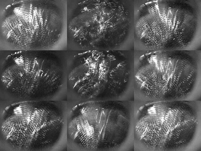
Figure 2 Water-filled speaker, showing ripples produced by low-frequency sound.
Channel Surfing Music
In chapter 6 we used coils to pick up the electromagnetic signals given off by various appliances and electronic devices. We can also eavesdrop on light signals of various kinds by using a specialized type of photosensor: the phototransistor (a variant on the photoresistor we’ve used throughout the book). A phototransistor is the heart of any infrared remote control receiver circuit, such as that in your TV. Most look just like an LED, so make sure you keep them clearly separated in your parts collection. You can find them at any electronic parts retailer. A phototransistor detects the pulses of infrared light sent by your remote control and converts them into a stream of binary pulse waves that are, in turn, translated back into digital data by the microprocessor in the TV. Earlier in this chapter we detected these data burst using a video camera, but phototransistors are cheaper (and smaller).
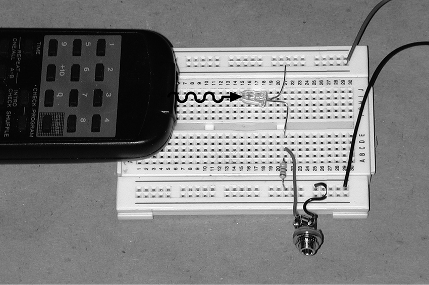
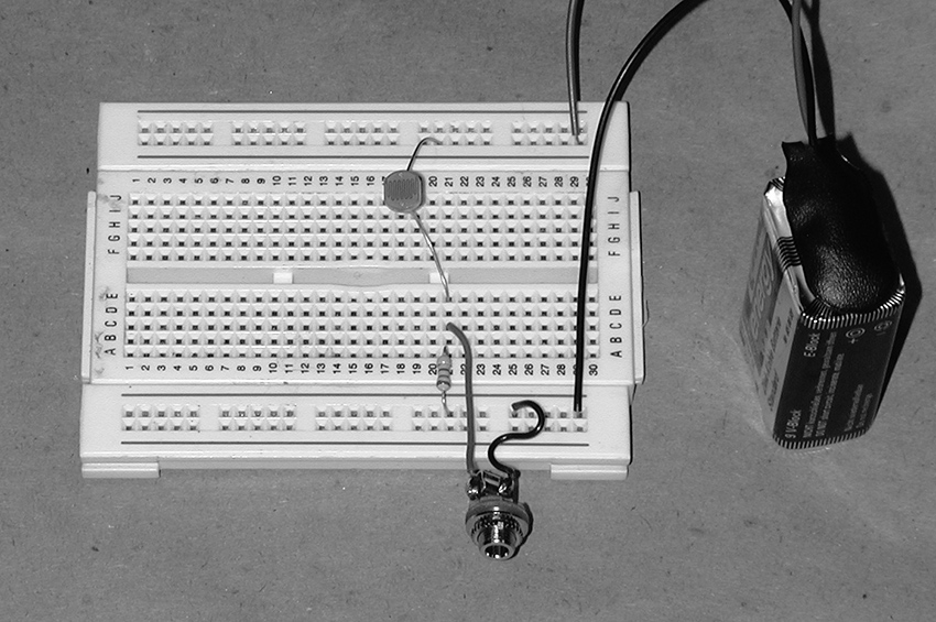
Aim a remote control at the simple circuit in figure 3. Keep it close, and you should hear pulse trains as you press the buttons. If not, reverse which leg of the phototransistor connects to +9 volts and which connects to the load resistor. Normally the phototransistor is “off” and the 2.2kOhm resistor holds the output to ground (0 volts). When infrared light strikes the phototransistor it turns on and effectively connects the output to +9 volts. Bursts of light from the remote causes the output to switch between 0 and 9 volts, just like our old friend the CMOS oscillator, only here the waveform is not a simple square but instead a cycling sequence of pulse waves of various duty cycles, which has rather a different timbre.
The variation between one button and another may sound pretty subtle: although the encoded numbers is different, the base frequency remains the same -- the effect is similar to listening to video, where the constancy of the fundamental sometimes overpowers the variations in image-dependent overtone content. Try several different remotes. You’ll notice that the loudness of the signal falls off pretty sharply as you pull the remote farther from the circuit, so you do have some dynamic control over this instrument.
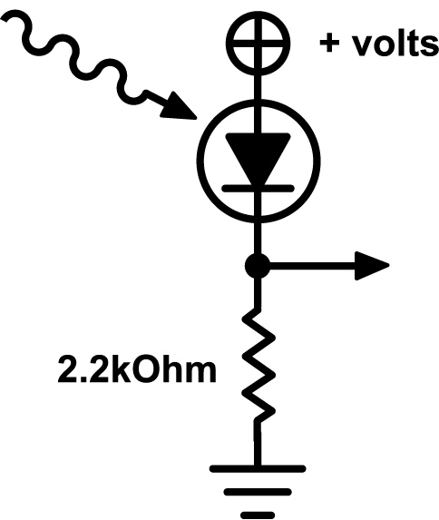
Figure 3 Simple phototransistor-based infrared detector circuit.
You can substitute an ordinary photoresistor for the phototransistor. You may need to increase the size of the load resistor from 2.2kOhm to 10kOhm or larger, as shown in figure 4. Because photoresistors are sensitive to light across the spectrum (not just infrared), you will get much more interference from the power grid’s AC frequency present in incandescent and fluorescent lighting (60hz in the United States, 50hz in Europe), resulting in an underlying drone. But you may find this interesting rather than irritating, so try it.
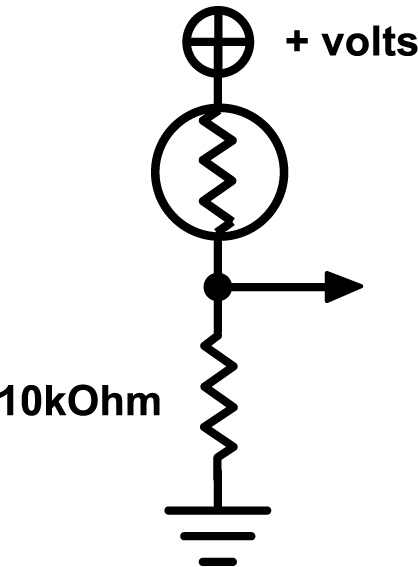
Figure 4 Photoresistor-based infrared detector circuit.
Although the lights on many electronic devices look steady, most are in fact “scanned” by the central processor unit. You can use our light-detector circuits to extract unexpected sound patterns from almost any gizmo with LEDs. Try it on bicycle flashers, toys with blinking lights, the front panels of studio gear, TV screens, computer monitors (as demonstrated in several audio and video tracks in the “Visual Hacking” gallery on this website). Certain bicycle lights and blinking toys sound astonishingly much like heavy metal chord progressions.
For greater variation try using the phototransistor or photoresistor circuit above as the control input to the basic 4093 gateable oscillator circuit from chapter 15. If you also use a photoresistor for the oscillator’s frequency control resistor, you get a pretty expressive “multi-phase” light-to-sound converter that responds to both ambient and modulated light sources, such as remote controls (see figures 5 and 6). Add a Theremin-style control of output volume (see figure 15.9) for additional expression.
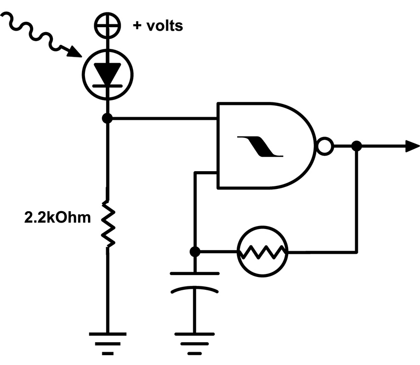
Figure 5 Infrared-gated oscillator with photoresistor-controlled frequency.
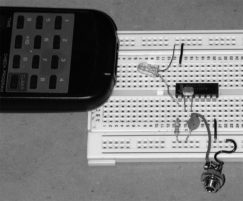
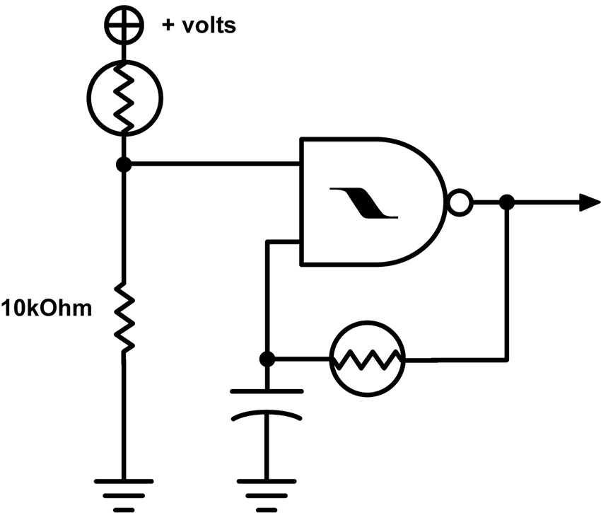
Figure 6 Photoresistor-gated oscillator with photoresistor-controlled frequency.
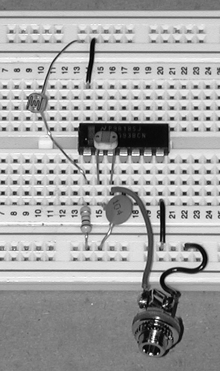
For a battery-free alternative you can connect a dozen or so phototransistor in series and hook either end of the chain up to the leads on a piezo disk (see figure 7). Aim an infrared remote at your circuit and you should hear a quiet, tinny refrain of the familiar pulse train. As we suggested at the end of chapter 15, clamping the disc to a resonator of some sort (matchbox, pie tin, etc.) will increase its loudness. Engineers at the Information Technology Research Institute at the National Institute of Advanced Industrial Science and Technology (Japan) used a similar passive design for an installation by Laurie Anderson in a Japanese Garden in Expo 2005 in Aichi, Japan. Visitors participating in “Walk” could listen to poems in four languages, transmitted with infrared light, and picked up by handheld “Aimulets” (see figure 8).
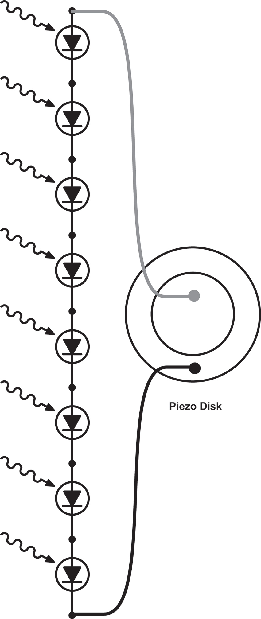
Figure 7 Phototransistor ladder driving a piezo disk.
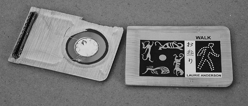
Figure 8 Walk by Laurie Anderson: photodiodes driving piezo disk directly, with molded bamboo resonator. Designed by the Information Technology Research Institute at the National Institute of Advanced Industrial Science and Technology, Japan. Photo © Laurie Anderson, used by permission of Laurie Anderson/Canal Street Communications.
Infrared transmitters and detectors are combined in the barcode readers used in our UPC dominated world – from handheld wands to the deliriously diffracted laser beams at supermarket checkout, all work by bouncing light off packaging and detecting the difference between light and dark stripes. Handheld devices, and their core elements, can be found quite easily and cheaply from electronic surplus sites on-line. Most require a 5-volt power supply (try 3 AA batteries in series). Sometime they come with wiring data, otherwise you’ll have to decode it (buy a few, in case of a real flameout). Hook up power, connect the data output to an amp, pass the wand across some barcode, and you’ll be rewarded with a noisy waveform similar to the tape head scratching transit cards in chapter 10 (no surprise here, since both the magnetic tape and the UPC are encoding binary data).
Since the barcode reading mechanism detects any light/dark difference, they can be used as generic image-to-sound translators: pass them over newsprint, photographs, TV screens, Dalmations, tattoos, facial stubble… Figure 9 shows two wands with a homemade power supply. The batteries are all that’s really needed, the extra circuitry in this box causes each wand’s data stream to alternate between the left and right output channels with each pulse, for a little more variety.
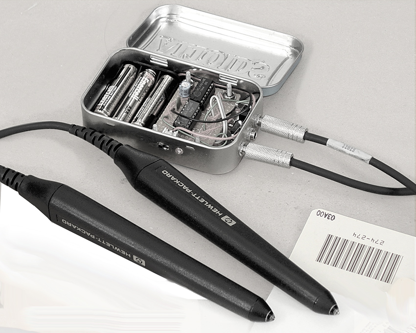
Figure 9 Two wands with a homemade power supply.
LCD Art
Making Animated Modern Daguerreotypes and Alternate Video Projectors
You will need:
- A toy with an LCD screen.
- Some test leads.
- A 9-volt battery and battery hook-up clip.
- Hookup wire.
- Some straight pins or short needles.
- A basic oscillator circuit from chapter 13 or 15.
- An amplifier.
- A flashlight and some lenses
- Hand tools, soldering iron, and electrical tape.
- Optional: an old-fashioned slide projector.
- Optional: a “video paint-box” toy with video output.
Lower Tech
A lot of handheld toys and games incorporate small LCD screens. In general-purpose LCD displays - such as laptop screens, flat-screen TVs, Gameboys and cellphones -- a matrix of pixels is bit-mapped in rows and columns by a microprocessor that turns individual pixels on and off to “draw” any character or image, etch-a-sketch style. In cheap toys, on the other hand, the screen usually contains a handful of “ready-made” graphic components: lips, a nose, and pair of ears are turned on and off against a printed cardboard backdrop to add distinguishing features to Mr. Potato’s otherwise generic oval head, for example. Although this approach severely limits the graphic options of any individual toy, it is much simpler from a programming standpoint, and therefore cheaper to manufacture.
These rebus-like images take on new meaning when the background is removed—leaving the body parts floating like a medium’s apparitions—or superimposed on an alternative drawing or photograph that you provide (Mr. Turniphead? Baby Sister rev. 2.0?). To accomplish this gentle re-purposing, disassemble the toy carefully (don’t lose those tiny screws or tear any fine wires), remove the cardboard backdrop, insert a new one of your choice, re-assemble, and prepare to amuse your friends.
The “narrative” of the game can sometimes be disrupted by shorting various points on the board, as we did in the “Almost a Short Circuit” section of “Beyond The Pot” on this website. In some cases injecting an amplified and distorted audio signal can also confuse or modulate the imagery (see chapter 20 for suggestions).
Although fewer in number than the tiny pixels in bit-mapped pixel grid, these graphic elements are still arranged in a matrix: the toy’s computer turns on individual images by sending logic signals through a particular row and column pair. When the screen is removed from the circuit its graphic elements can be activated with simple connections of voltages, either directly from a battery or from an oscillator. Start by tinning the tips of the red and black wires from a 9-volt battery clip to give them stiff, sharp points—you can also solder sewing pins to the wires for stronger, finer contacts.
Locate the connections to the LCD. The glass element is often connected to the circuit board through a thin rubber strip (usually pink, for some incomprehensible reason) containing a thinner strip of black conductive rubber filaments. If you look closely you’ll notice that what at first may have appeared as a solid stripe actually resembles a dotted line – each dot is one end of a thread of the same material as those funny rubber hats used as keys on many toys. One end of each of these filaments presses down against a trace on the circuit board, while the other touches a narrow, ghostly grey finger on the edge of the LCD, linking the display to the circuitry. Usually this kind of LCD has connections on two or four edges of the screen. Some older LCDs have larger metal tabs that are soldered directly to the circuit board.
Poke the “+” lead from your battery against a dark point in one rubber strip, and press the ground wire to another point, on the same strip or another. If you remove the rubber strips, you can usually make direct contact with the LCD connections by pressing the wire tip directly to the glass where the rubber sat, or by clamping the jaws of a narrow clip lead to the edge of the glass. Look carefully: you should be able to see very fine lines etched on the glass—these are the electrical contacts. Move the probe or jaws along the edge and catalog the hot spots for the individual screen elements. If the screen has more substantial metal connections poke them directly (see figure 1). Try different pairs of contacts while watching the screen—at some point an LCD element should become visible. Make a note of the location of the contact point pairs that enable specific graphic objects, and keep exploring. Once you find a set of images that you like, you can make the connections more stable by wedging and taping wires or pins into or against the contact strips.
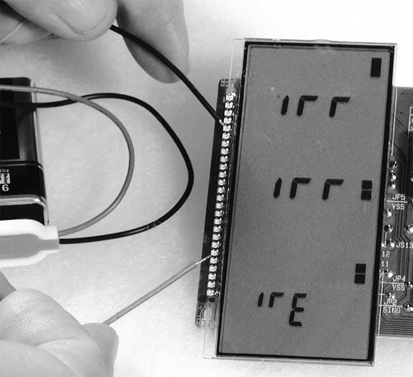
Figure 1 LCD elements being activated by direct battery connection.
You can animate the images by using the outputs of oscillators to blink the LCD elements instead of setting them “permanently” on with battery leads. Breadboard a simple oscillator with a 74C14; use a larger capacitor (2.2-10uf) and a big pot so it runs at a low, metronomic speed. Take one lead from the output of the oscillator one from the circuit ground (battery “–”). Connect the leads to points along the LCD edges that you know enable images (see figure 2). Adjust the oscillator speed and watch the LCD element turn on and off. If nothing happens, swap the oscillator output and ground connections to the LCD, or try different contact points. Continue to add more oscillators until you achieve the visual texture you want. When more than one oscillator is connected you can usually remove the ground lead from your circuit and just use oscillator outputs – the interaction amongst low and high outputs of the various oscillators activates the matrix. Alternatively you can connect jumpers between any electronic circuit (such as a bent toy) and contact points on a device containing an LCD screen and search for interesting modulation effects.
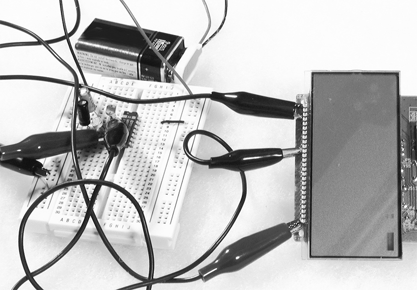
Figure 1 LCD elements animated by oscillator outputs.
LCDs are kind of spooky—the image often lingers on the screen for several seconds after power is disconnected before fading out. The small screens bear a resemblance to old daguerreotypes (although Berlin artist Martin Riches reminds me that daguerreotypes had resolution so fine as to be discernable on a molecular level, in stark contrast to the crude pixilation of an LCD). They have a certain charm as modern miniatures, whether superimposed on new backdrops or left in their rather ghostly, mostly transparent state as tiny digital stained-glass windows. They are lovely hung in a sun-dappled cottage window.
The current consumption of the LCD device and a low-frequency oscillator is so small that you can leave the object running on a 9-volt battery for weeks before it runs down. You could even power the whole thing with a small solar panel (especially if you do choose to hang it in a sunny window). If you go shopping for the latter, look for one that puts out anywhere from 3 to 12 volts, with a current capacity of 5 milliamps or so. Some CMOS and LCD circuits can even be powered by a battery made from an apple or potato. So dust off those childhood science fair notes, or study the “Power Supplies” section of the Technical Bootcamp on this website for some alternative energy sources.
With a decent light source and the appropriate lens you can project your LCD onto a wall -- experiment with flashlights or bright LEDs and some lenses. Invest in one of those “third hand” devices: use the two articulated arms with alligator clips to hold the LCD and a lens to focus the image projected by a narrow-beam table lamp. You’ll have to remove any printed backdrop, of course, and some LCDs without a background picture use a simple self-adhesive reflective tape that must be peeled off to make them transparent.
You can also drop the LCD screens from tiny portable “stadium TVs” into older slideprojectors (see section on BMBCon in “Visual Music”). The screens of many older mini-TVs fortuitously have the same dimensions as a 35mm slide. You can do the same with the displays from many cheap hand-held games—the stupidest thumb-driven hockey match looks pretty cool projected huge, upside-down and slightly fuzzy on a wall. LCDs can be damaged by excessive heat – it helps to add additional fans to cool the slide well in the projector.
Don’t let the visual charm of LCDs distract you from their sonic potential. Clip the ground half of an audio cable to the battery ground of a working LCD circuit (before you do the hacks described above) and touch the hot lead to the various scan lines of the LCD display: you often hear deep, rich chords.
Higher Tech
Several companies specializing in high-end electronics toys, most notably V-Tech, make “video paint boxes” for children. These devices connect to a television and include a simple graphics tablet and keyboard with which the kid creates drawings and animations. Inside are some very sophisticated graphic chips that can be bamboozled into doing strange things. Following the technique described in “Beyond the Pot”, use wire or clip leads to interconnect any points on the circuit board. Occasionally you will get lucky and find connections that cause the graphics engine to freeze mid-way through drawing an image, re-color blocks of pixels, superimpose graphics from its memory, etc. Since these circuits usually use crystals for their clocks, any clock speed modification will probably require replacing the crystal with CMOS oscillator, as we discussed in chapter 15. And while you’re at it don’t forget to listen to different points on the board as well.