Project Support
Sharing Traces
Designing and Fabricating Your Own Printed Circuit Boards (Eduardo Rosario): Data files for Fritzing and Eagle projects
Download Data files for Fritzing and Eagle projects (ZIP 125KB)
Sharing Traces
Designing and Fabricating Your Own Printed Circuit Boards with Eagle (Eduardo Rosario)
This is an extension of chapter 32 in the printed book, “Sharing Traces: Designing and Fabricating Your Own Printed Circuit Boards with Fritzing.” Here we will shift our focus from Fritzing, a popular hobbyist/hacker application, to Eagle, one of the “industry standard” software packages.
Autodesk’s Eagle is one of the standard EDAs used by professional electronic engineers and amateurs alike. As a hobbyist you can download a free version of Eagle—a Personal Learning License for individual and non-commercial use—and students can get an Educational License to use Eagle for free. This is a great way of familiarizing yourself with what it can do. Go to Autodesk’s website, and under Products you will find Eagle. Under “Overview” the options for both licenses will be available to you. Either of these two are good enough for what we will do. Take the time to navigate the website, read about it and view what it can do. Installing Eagle is easy, just follow the instructions. Once installed, launch it. A pop-up window will ask you to sign in. Eagle provides you with two different editors: one for schematics and another for board layout. These two spaces are synchronized in real-time.
Eagle’s Control Panel is the first thing you see when the program is launched (figure 28). In the Control Panel you have access to the different aspects of a project and Eagle’s configuration. On the left you have a list of drop-down menus. These all offer ways of working your project. I will explain these as we go.
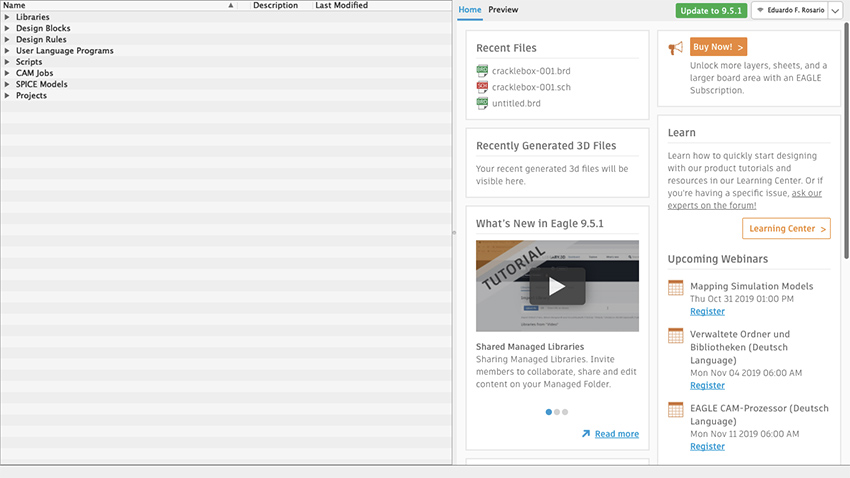
Figure 28 Eagle Control Panel
Libraries are a powerful feature of Eagle, and we’ll start by installing SparkFun and Adafruit libraries. These will come very handful, because these include standard stock parts from Sparkfun and Adafruit projects, such as audio and barrel jacks, potentiometers, common chips, and so on. All you need to do is explained on this step-by-step guide: www.autodesk.com/products/eagle/blog/library-basics-install-use-sparkfun-adafruit-libraries-autodesk-eagle/
Download the libraries from their Github repositories. If Github is new to you, then just click on Clone or Download and select Download ZIP. Create a folder in your Documents directory and copy/paste the extracted files there. Now go to Eagle’s control panel and on the Options tab, select Directories. The first path on the top is for the Libraries. Instead of having $HOME/Documents/EAGLE/libraries change the path for $HOME/Documents/eagle_external_lbrs and click OK.
Go to the Control Panel and under Libraries the “new external libraries” folder will show up, but these have not yet been activated. You’ll notice a gray dot is next to each item in the library. To activate the libraries, right click on the library folder, select “Use All”, and all those gray dots are now green. SparkFun and Adafruit parts are now available for use in Eagle. As your skills develop and projects grow in complexity, you can create your own custom libraries in Eagle.
Now move to the Projects folder at the bottom of the list of the control panel. When opened, two subfolders will show: “Projects” and “Examples”. If you are curious and have time, feel free to explore the Examples folder, where you will find many references on what Eagle can do. The user’s Projects folder will be empty.
Let’s create a new project. It’s good to start by making a new Project folder. Right click on your Projects folder, select New Folder and name it as you please. I will call mine HEM_PCBs. Now right click the new folder and select New Project. Name it however you want; mine will be called Synth4584-001. Notice that next to your Project there is a green dot, which indicates the currently active project. The dot for every other project will be gray and slightly smaller.
Schematic
Right click on your new Project, go to New and select Schematic (figure 29). (In Eagle you do your design work in schematic form, rather than on a virtual breadboard, as we did in Fritzing; this might make the process more difficult for beginners, but has the long-term advantage of making it easier to import circuit designs from the rest of the world). The Schematic Editor window will open (figure 30). In this editor you can work out the logical representation of your project. On the left is the toolbar with all the different commands. From the top downwards, you will see many other features, including a command line right before the white working surface. The little cross on that surface is the origin, point 0, 0. It is not moveable.
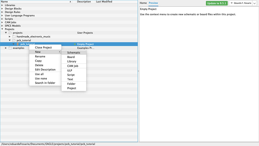
Figure 29 New Project window
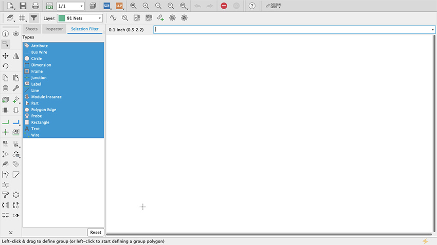
Figure 30 Schematic editor
On the top-left you will see a little grid (figure 31). Click on it and a new pop-up menu will open. Where it says Display, select On and then click OK (figure 32). Your working surface now looks like graph paper. This is very important because everything you do will snap to that grid even if the display is off. By default, the spacing of the grid is 0.1 inch and it is strongly recommended to use that default settings: everything in the schematic editor is spaced at tenths of an inch and, since everything snaps to the grid, you can confirm that each connection was made successfully. An even finer grid will be available if you press the alt key, but my advice is to limit its use only for graphics or notes but not for the actual schematic.
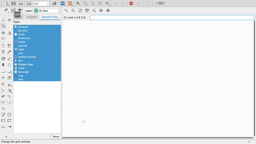
Figure 31 Grid
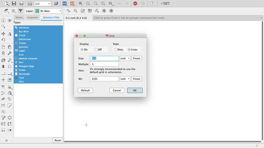
Figure 32 Display Grid
Let’s start putting things together. On the toolbar there is something that looks like an AC power plug with a green + symbol (my guess is that it is a symbol for an AND Gate) (figure 33). If you hover your cursor on top it will say “add part”. Click it. This is how you get access to all the parts libraries that come with Eagle. In here you will find pretty much everything you might need; if not, new libraries can be made and/or installed (as we did at the start of our Eagle tutorial) (figure 34). You access these through the Control Panel’s Libraries dropdown menu (figure 35). The important thing to know is that Eagle’s part library’s search bar cuts no slack to anybody: it will look for exactly what you type. This can be frustrating and can lead you to think that none of the parts that you need are available on Eagle. Because of that, Eagle allows the user to include wildcard characters as part of the search, including the question mark (?) and the asterisk (*). The question mark is for just one character and the asterisk for any number of characters. Sometimes, for example, integrated circuits come will all sort of prefixes and suffixes which are hard to remember. When you look for just the digits that you remember, nothing shows up even though it might be the standard name of the part. In that case wildcards can help.
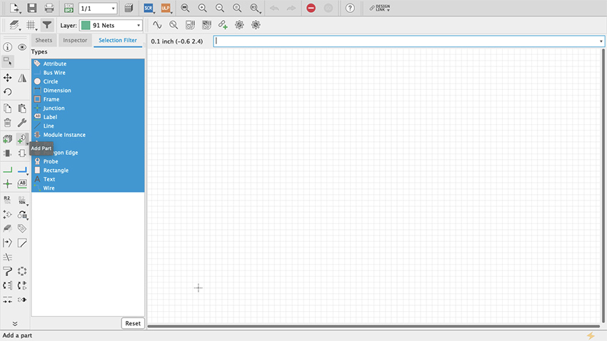
Figure 33 Add Part Command
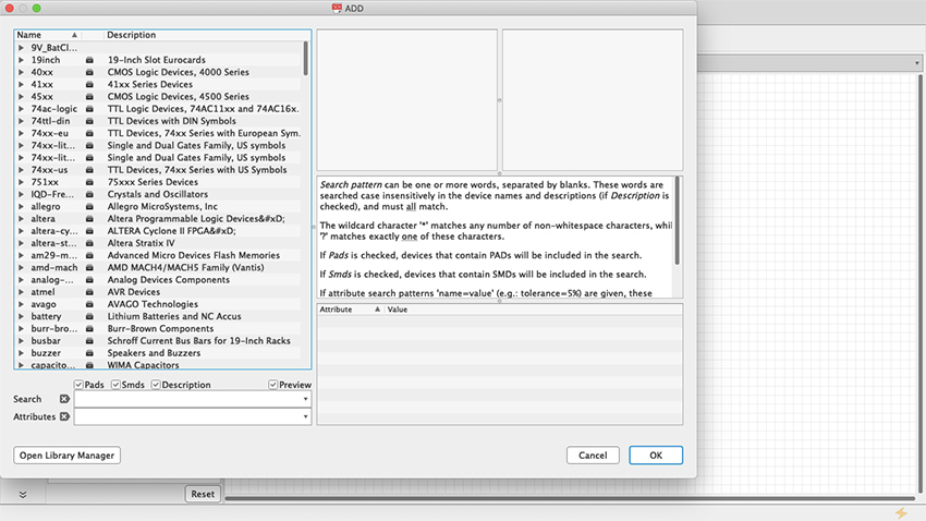
Figure 34 Add Part Menu
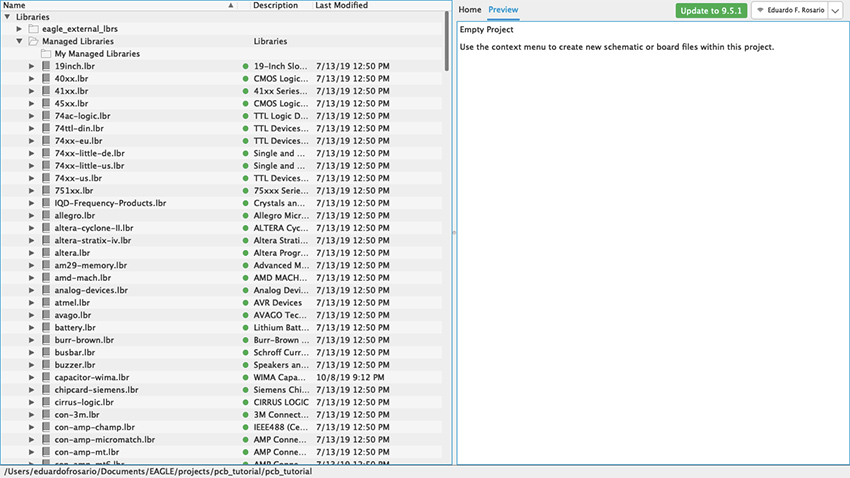
Figure 35 Libraries Control Panel
For our simple synth project, the first thing we need is the Hex Schmitt Trigger we used in our Fritzing tutorial. If you type 4584—which is one of the names the chip goes by—nothing will show up. It will say on the right “Sorry, no match!” (figure 36). But if you search for “4584?” the part will show up because there are two flavors of the same chip each with a different character at the end: D for small outline (SO) package and N for dual in-line (DIL) package (figure 37). Entering “Hex Schmitt Trigger” will reveal more than one part, “74C14” will have the same result as “4584?”, and searching “74*” or “45*” returns long lists (figure 38).
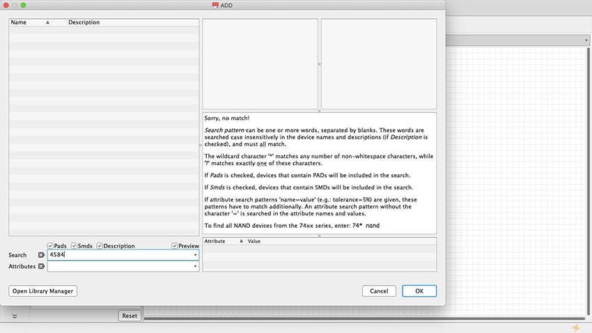
Figure 36 Sorry no match
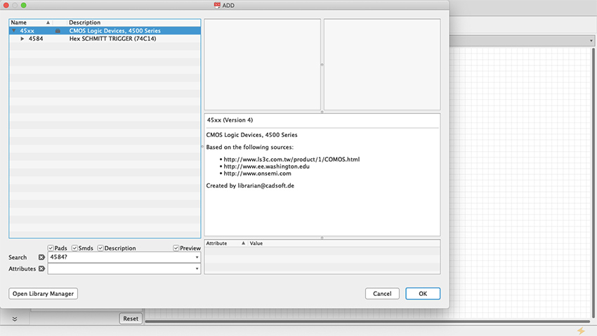
Figure 37 ? Wildcard
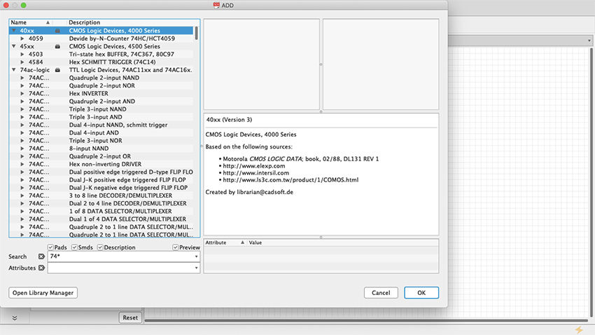
Figure 38 * Wildcard
The Hex Schmitt Trigger has six inverters on a single chip. When you select the part from the library it will give you the first inverter of the chip (Figure 39), but as you keep stamping the part across the schematic sheet, each iteration will consist of a new stage, respectively labeled IC1A, IC1B, IC1C and so on, until all six have been used up; stamp some more and Eagle will add a second chip, and you will see IC2A, IC2B, etc. (Figure 40).
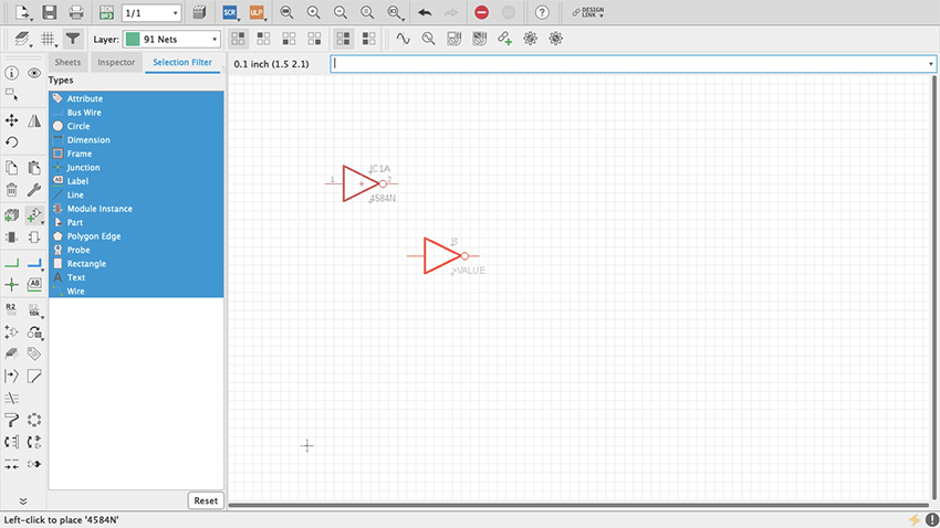
Figure 39 A single inverter
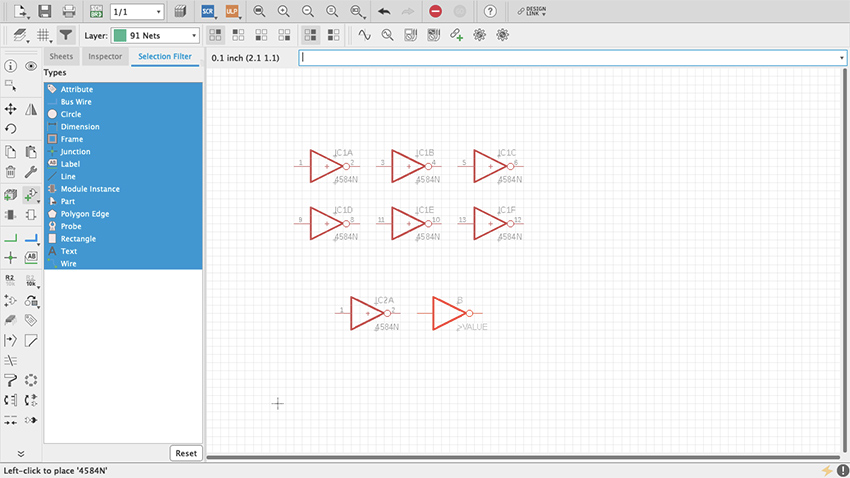
Figure 40 All inverters
Start by adding power and ground as we did with Fritzing. These will be found on the supply1 and supply2 libraries. Select VCC (+ V) and GND from either supply1 or supply2 (Figure 41, 42, 43). As long as they have the same name, power and ground busses are always connected and therefore do not need to be physically connected together in the schematic. Copying and pasting VCC and GND wherever necessary is enough. But, where and how do we connect them? As you have probably noticed already, the power and ground pins of the Hex Schmitt Trigger (7 and 14 respectively) are not available even after you have pasted all six inverter sections. We need to ask for them which we do by right clicking on the little cross at the center of the chip—that is the part origin—and selecting “Invoke” (Figure 44). A pop-up window will show a list, at the bottom of which you will see “P PMRN request 0” (Figure 45). Select it and click OK. Two new pins appear, which you can place on top of the part using the origin for reference (Figure 46, 47). By default, the top one will be + power and the bottom one ground. To make connections in the schematic editor, select in the toolbar a green L shaped symbol called Net (Figure 48). Once selected, whenever a connection can be made, a hollow green circle will appear when hovering the cursor. Arrange the parts as you see fit in the sheet and make the connections (Figure 40). Resistors, capacitors and inductors are found on a library called “rcl” (Figure 50, 51, 52). For power connect a 9v battery clip to the wire pads (Figure 53). Then add an audio jack (figure 54, 55, 56, 57, 58, 59).
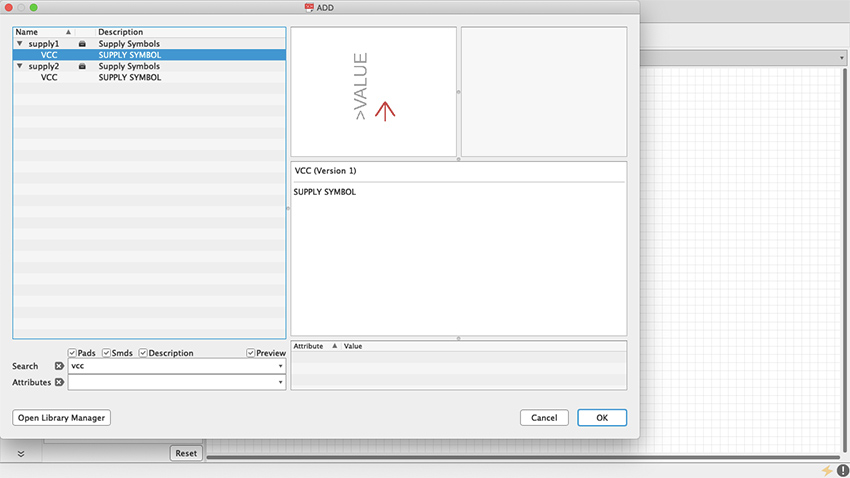
Figure 41 VCC
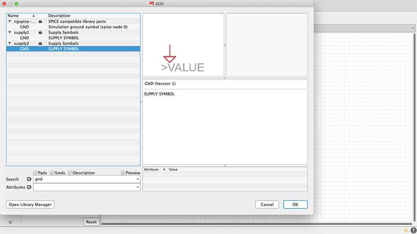
Figure 42 GND
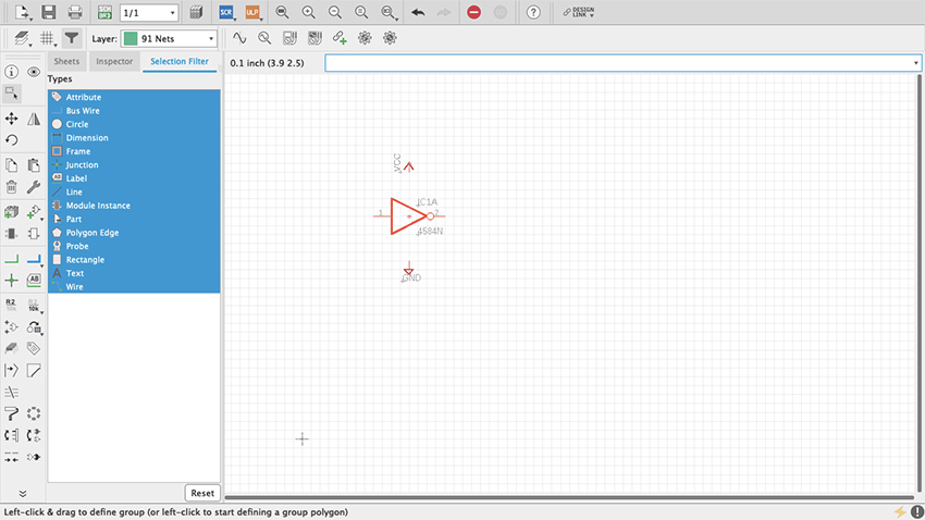
Figure 43 VCC & GND in Schematic
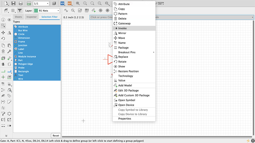
Figure 44 Invoke
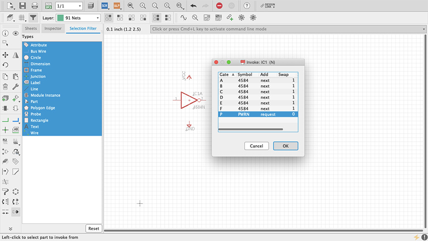
Figure 45 Invoke Box
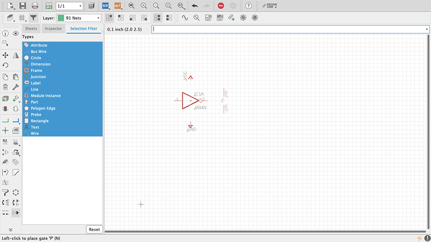
Figure 46 VCC & GND Pins
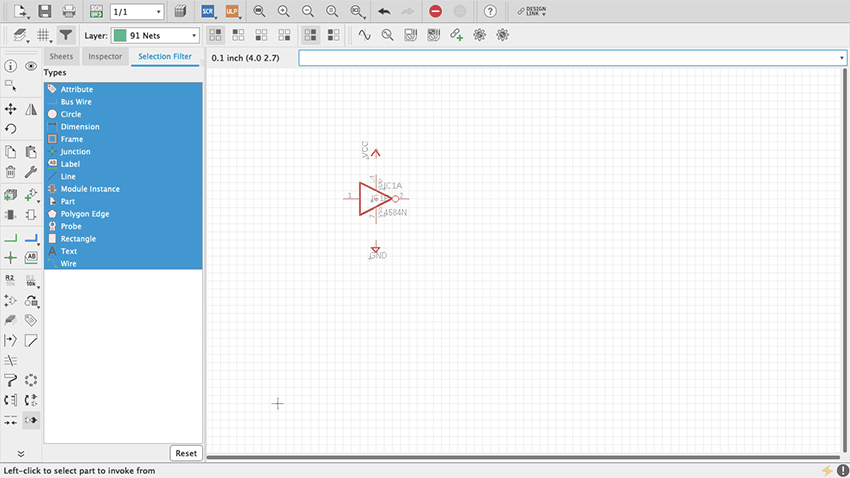
Figure 47 VCC & GND Pins
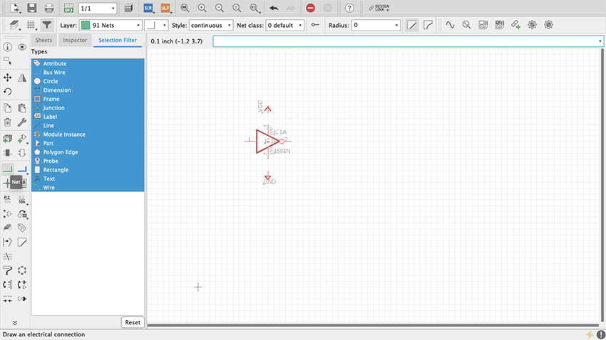
Figure 48 Net Command
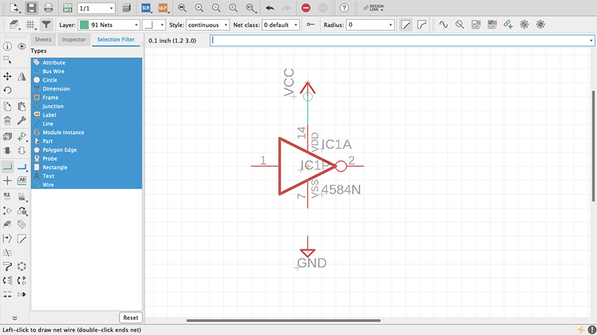
Figure 49 PWR Pins Connected
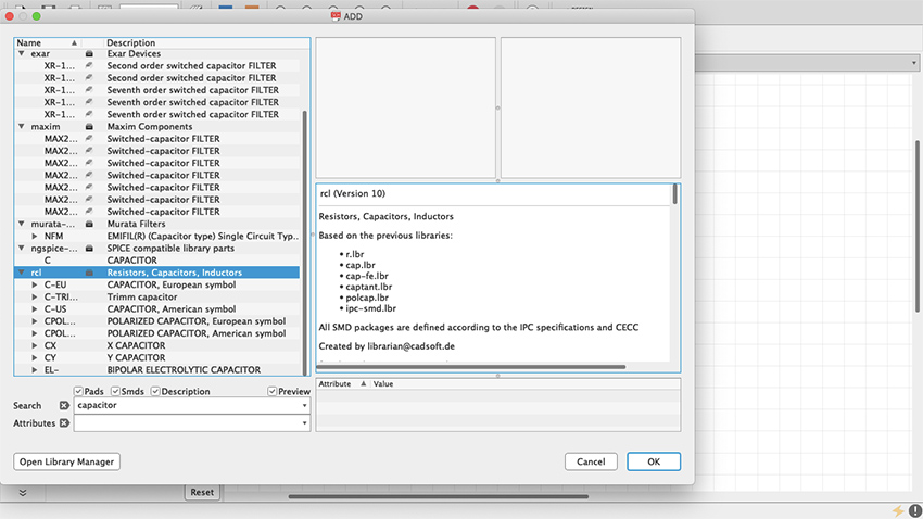
Figure 50 rcl library
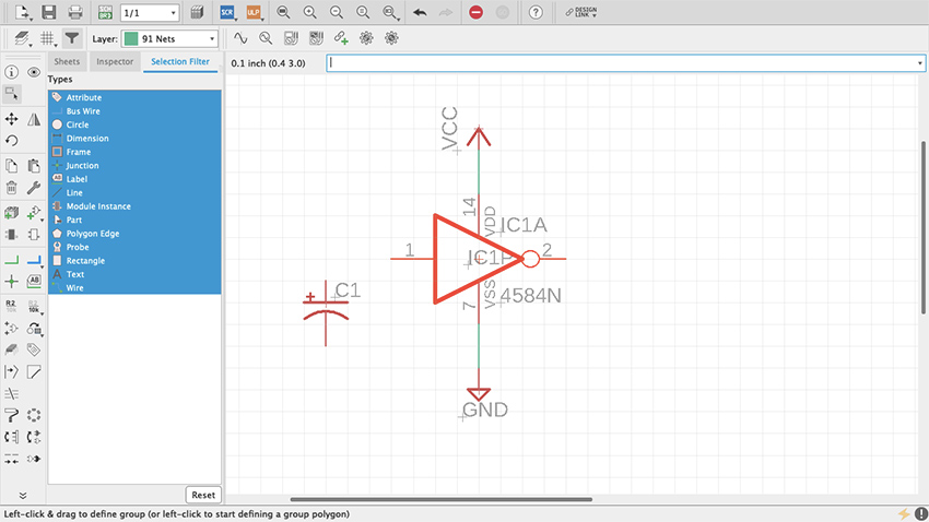
Figure 51 Capacitor
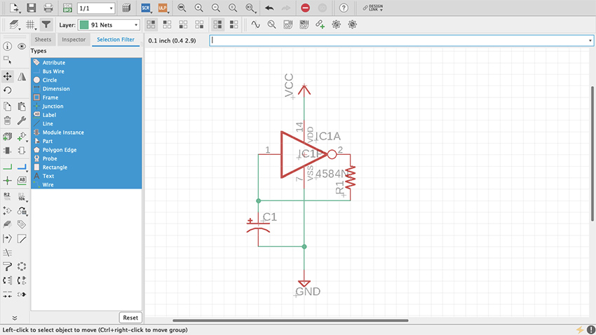
Figure 52 Resistor and Capacitor
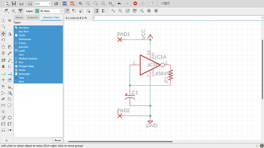
Figure 53 Wirepads
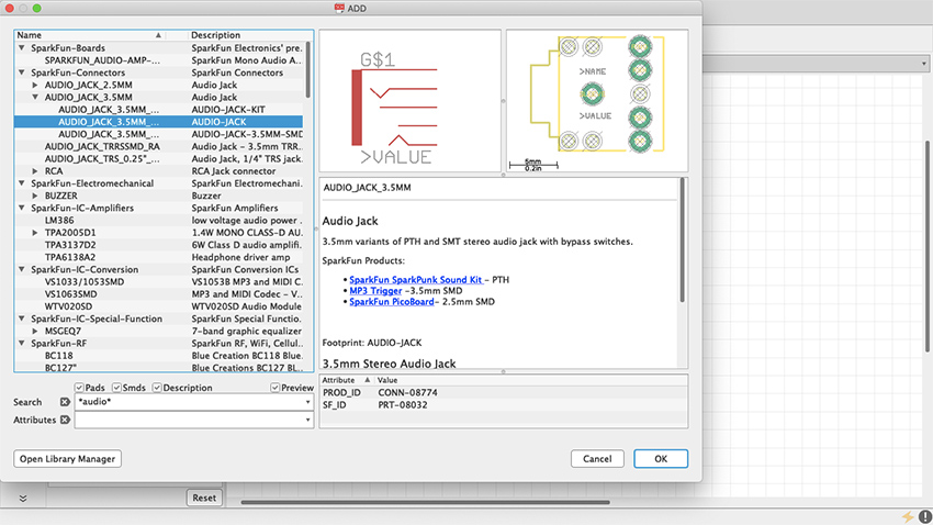
Figure 54 Audio Jack
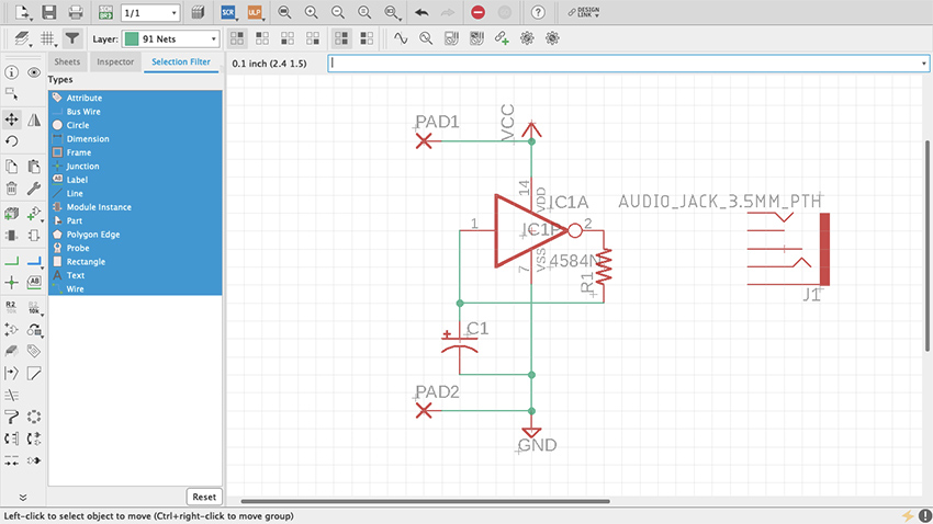
Figure 55 Audio Jack in Schematic
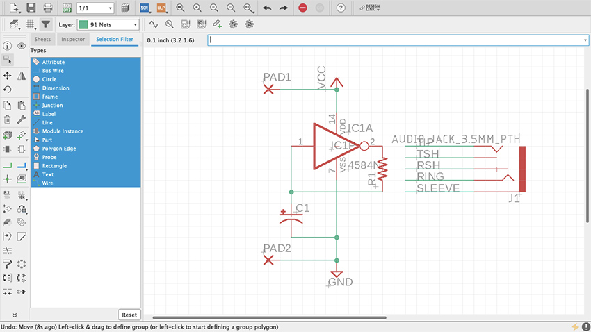
Figure 56 Audio Jack Pins
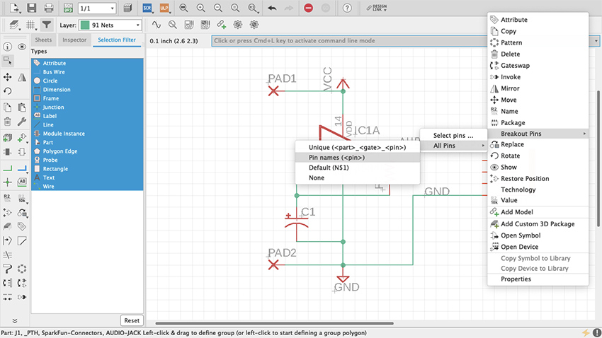
Figure 56.1 Audio Jack Pins
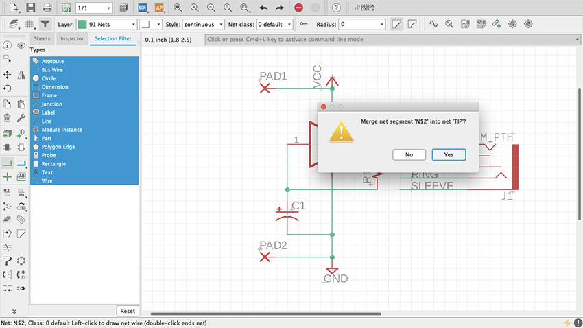
Figure 57 TIP-Audio Jack Pins
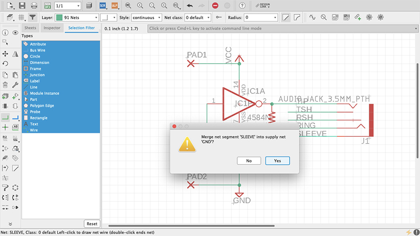
Figure 58 SLEEVE-Audio Jack Pins
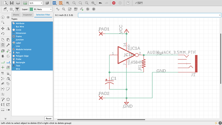
Figure 59 Audio Jack Connected
Board Layout
Now that the schematic is done, it’s time to work on the board layout. At the top of the editor, to the right of the Print icon, there is a gray and green square that reads SCH BRD. Click it. It will prompt a message saying that the board does not exist and ask whether it should be created (figure 60). Click “Yes” and the board layout editor will open. On this editor many new features are introduced. New items have been added to the toolbar on the left and others are no longer available. Next to it is the Design Manager (figure 61), which is a powerful tool that will help monitor and properly manage the board layout. If it is not there by default, open it through the View tab on top.
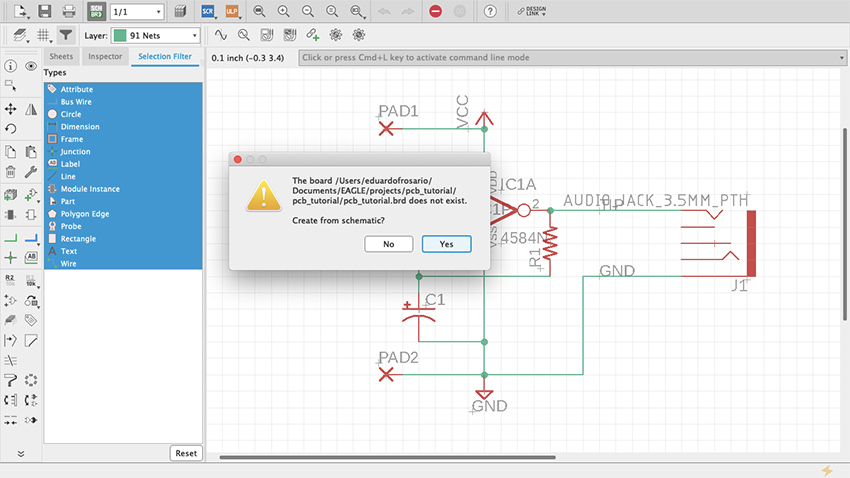
Figure 60 Create from Schematic
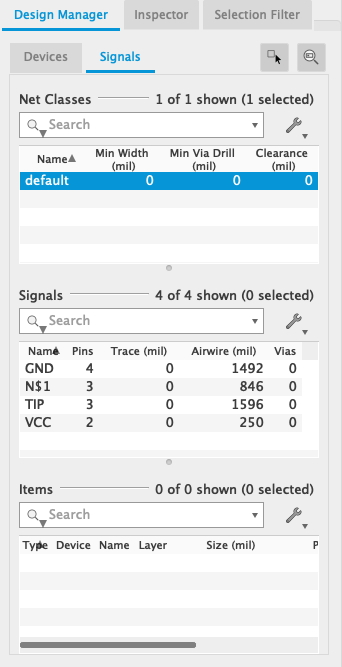
Figure 61 Design Manager
Unlike working with the schematic, in the board editor the grid can be changed as needed. It will default to twentieths of an inch, but any desired measurement can be used. Even though the pins of the integrated circuit we are using are spaced at a tenth of an inch from one another, the components that connect to them can be freely placed around it. Turn On the display and adjust the grid to your preference. Additionally, if you go Options > User Interface, you can change your cursor from Small to Large (figure. 61.1). This is optional but I think the larger cursor is useful for arranging parts on the board. (This feature is also available for the Schematic view.)
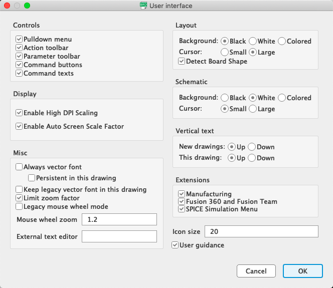
Figure 61.1 Cursor large
As mentioned before, both editors on Eagle are synchronized. Eagle keeps track of what happens in one editor and translates that into the other immediately. Closing one editor and working on the other will disturb that synchronization, and not only is the project’s health at a high risk but trying to undo changes is the thing of nightmares. That is why, when an editor is closed, Eagle will let you know that synchronization has been lost with a yellow and black warning ribbon (figure 62).
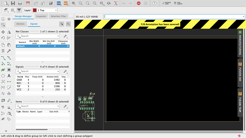
Figure 62 Sync warning
A very important part of both editors is the Layer Settings (figure 63, 64). When working in the board layout, this feature will acquire particular prominence as the different components are distributed across the board. Access to the Layer Settings is available through the toolbar by clicking on the stacked-up rectangles above the Move command. All layers will be listed on this menu. Visible ones will have an eye on the left. PCBs usually consist of a substrate (such as fiberglass) with copper, soldermask and silkscreen layers on each side. On Eagle, the Top copper layer is red and the Bottom copper layer is blue (unlike Fritzing which is yellow and orange respectively); Pads and Vias are green; Dimension, which is the board outline, is mustard yellow; and other layers such as the Drills are gray. You will probably memorize this as you work. If some work needed to be done on a particular set of layers, here is where they are managed.
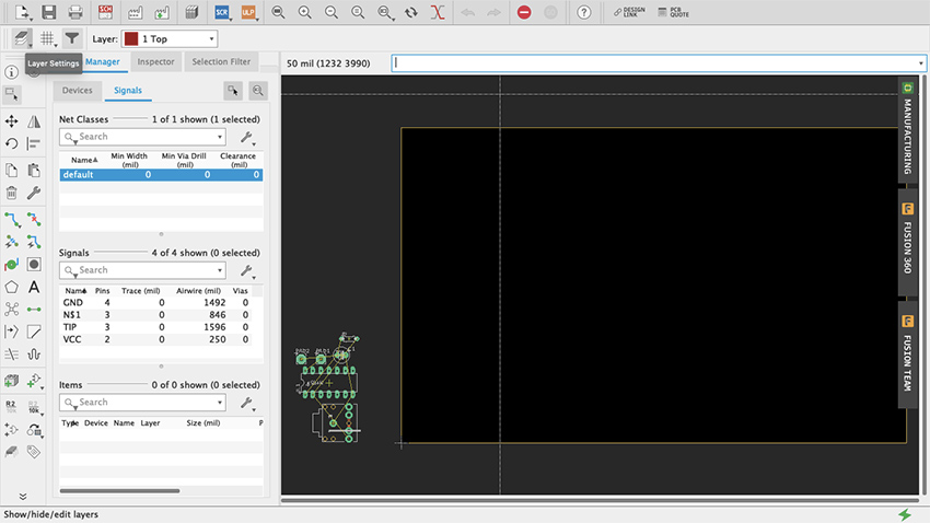
Figure 63 Layer Settings
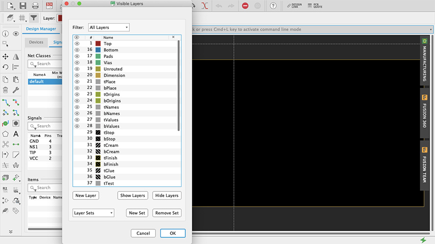
Figure 64 Layer Settings Menu
To keep things simple, we will design a single-sided board. This means that all parts will be placed on the top and all traces will be on the bottom (like when using a generic proto-board). Even though circuits done in this chapter are quite simple, you can do a double-sided board if you wanted to. But if you are milling the board yourself I would recommend sticking to single-sided for now (see “Milling PCBs” below).
All the parts of the design will be placed at the bottom-left of the workspace (figure 65). The black rectangle with yellow borders is the board. It can be modified as the design is being worked. Using the Group tool, move everything onto the board (figure 66, 67). There are yellow lines connecting the parts. These are not traces on the board but “airwires”, and they show how everything is connected. Start by arranging the parts however you please on the board. Use the airwires as a reference on how to distribute the parts. Clicking the Ratsnest button (figure 68) will recalculate airwires -- it looks like an X made with five circles and is located below the Polygon command (which looks like a pentagon). If airwires bother you, open the Layers menu and deselect the Unrouted layer. Start by placing the chip, which is the most complex part, and then add supply, resistors, capacitors, diodes and jumpers (figure 69).
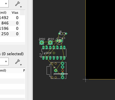
Figure 65 Parts at the bottom-left
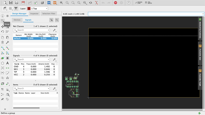
Figure 66 Group Tool
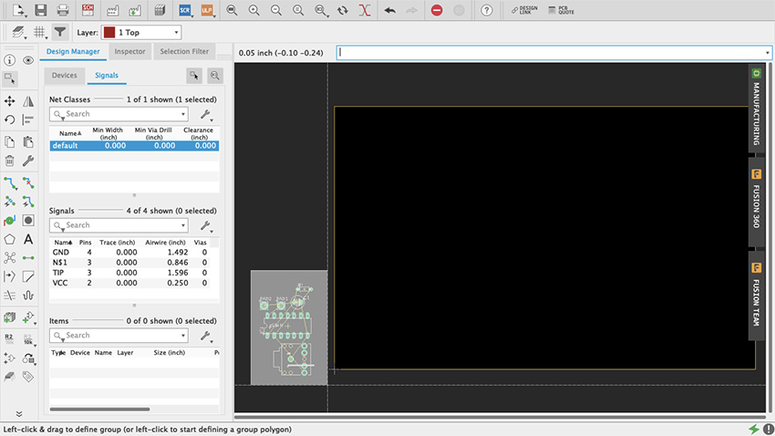
Figure 67 Group Tool Select
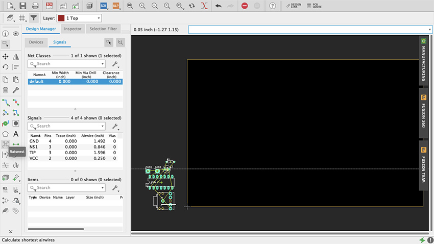
Figure 68 Ratsnest
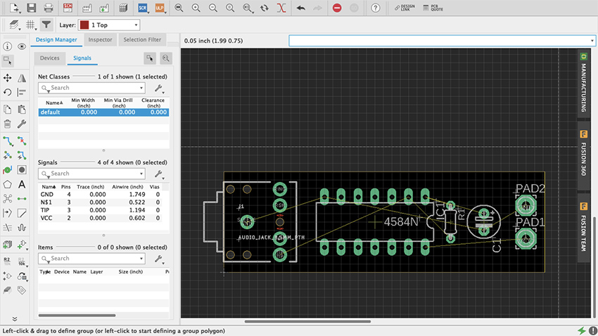
Figure 69 Parts arranged
To make the traces we use the Route command (figure 70). In the toolbar it is the one right below the Rotate command, represented by two green dots connected by a blue trace. An arrow pointing downwards on the Route icon accesses a few additional modes of this command (such as Quick Route Signal). Route Airwire should suffice for now, but if you are feeling curious try the other modes and see what they do. Above the workspace and the command line are additional important settings for this tool. Start by selecting “16 Bottom” on the Layer drop-down menu since we will be making a single-sided board with all the traces at the bottom. Right next to that are some routing behavior settings. “Walkaround Obstacles” will be selected by default and that is good. On the Width menu, since it is a simple circuit, you can go with nice thick traces—0.024 or 0.032 are good values. Thicker traces are preferred when milling your board since thin ones peel off easier. For a single-sided board don’t worry about Vias shape or Drill size. For double-sided boards, round shape and auto Diameter should be alright. Make sure that Drill size is at least c. 0.02; the default value is probably alright, but I would recommend checking the board house specs (more on this later). For the Wire Bend, experiment as you go.
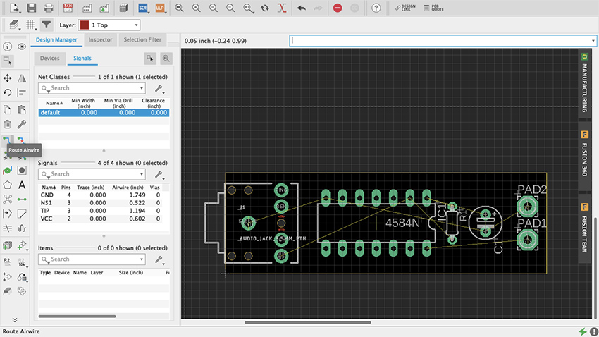
Figure 70 Route
To route a trace just click at one end of an airwire and complete the connection to the other end (figure 71, 71.1). As traces are being made the Route command will make suggestions on how to proceed. Clicking along the way creates fixed joints around which the traces will pivot. Once a trace is finished Eagle will make a sound and the name of the signal will be assigned to it. Vias allows you to move a signal from one side of a double-sided board to the other: simply press down your mouse’s scroll wheel or middle button, or manually change the layer and for the next trace a Vias will be on your cursor. To delete a trace just use the Ripup command (figure 72), to the right of Route on the toolbar, with a little red X. Play with the Route tool. Try different trace widths, try drawing shapes, see what kind of narratives can be told, explore how different arrangements of parts and traces affect the overall functionality of your design.
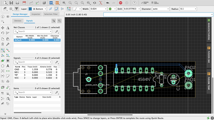
Figure 71 Making traces
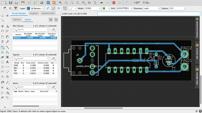
Figure 71.1 All traces
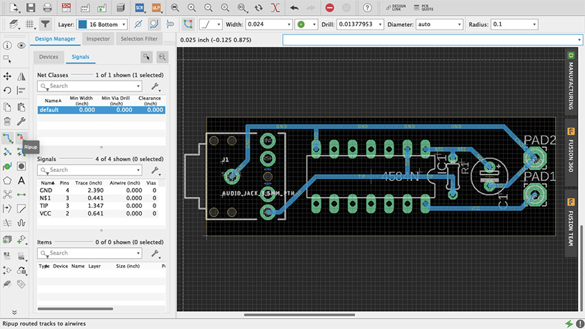
Figure 72 Ripup
Another way to proceed is using the Autorouter. In the Toolbar it looks like the Route command but with a little lightning bolt. Do not think of this as an easy way out but as a different approach to problem solving. Similar to Fritzing, it is highly unlikely that the solution that the Autorouter will come up with will be the best option – lots of editing afterwards. When selected it will prompt a Setup menu (figure 73). Try the default settings (if it is a single-sided board leave just the Bottom in Auto and select N/A for the Top) and press Continue. A Routing Variants window will appear, press Start. Once it is done, select one of the alternatives it came up with and press End Job. Now patiently edit the traces to fit your design’s needs.
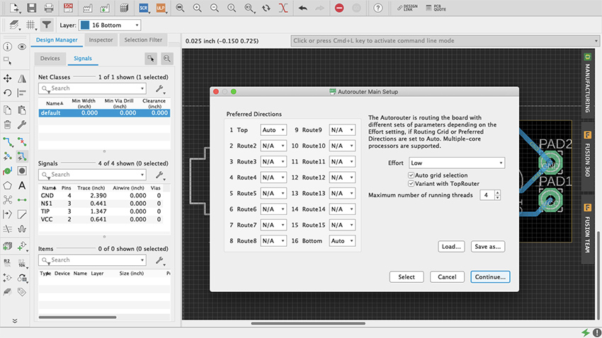
Figure 73 Autorouter
Fortunately, when routing one trace at a time, or editing the Autorouter’s traces, there is a way to make sure everything is correct: the Design Rule Check (figure 74). You will find it either under the Tools tab in the menu bar as DRC, or in the Toolbar when expanded using the double arrow at the bottom. The DRC will let you know whether your design meets specific manufacturing requirements. When opened, a setup window will appear with multiple tabs, each storing the default values for various important aspects of your design, such as the minimum distance between objects, minimum drills and width, etc. After you are done making traces go ahead and do a check with the default values. If there are any issues a DRC Errors pop-up window will appear (figure 75). For example, if some connection has been left unrouted, it will appear as an Airwire under Errors. If you select a specific error in the menu, Eagle will indicate where it is in your Board Layout. If there are no errors (wheee!) you will see in the bottom left corner a message that reads “DRC: No errors.” You can also load third party design rules with .dru files.
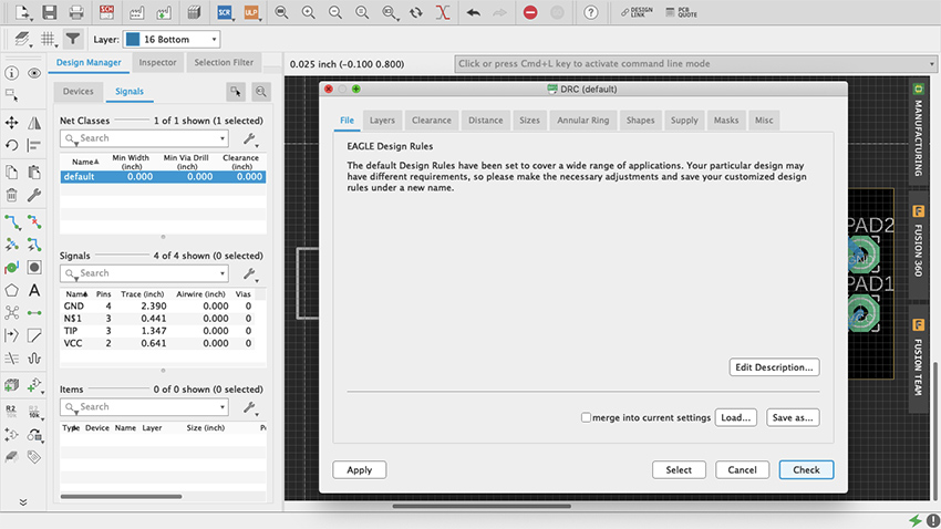
Figure 74 DRC
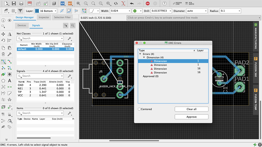
Figure 75 DRC Error
It is common practice to do a “copper pour” at some point when doing your board layout. A copper pour is when an “open” part of the board is filled with copper and connections are made to it. The most common use is as a ground plane, which reduces noise in circuits. Some do it at the beginning to simplify what could otherwise be a complex design to route, and others do it at the end as nice finishing touch with practical benefits. It is not obligatory, yet it does not hurt to do so, therefore it is up to you. Copper pour in Eagle are easy. Select the Polygon tool (figure 76) and draw your board’s outline on the desired layer, either Top or Bottom (figure 77). Once you have completed the shape, a dialog box will ask you to enter the signal’s name, which is usually ground, named GND or something similar (figure 78). If you are not sure, check with the Design Manager. Once you have entered the signal the polygon’s outline will be dashed (figure 79). If it never asked for a final name to be entered, use the Name command that’s between the Design Block and Copy commands, as “R2 /10k” (hover your cursor on top of it and it should say “Name”) (figure 80). Click the polygon outline, enter the name and select the “this Polygon” option (figure 81). To finish select the Ratsnest command and copper should cover the entirety of the “open” board surface, avoiding all traces other than GND (figure 82). All GND traces now connect to this plane and every other path should have the minimum clearance from it. Depending of what your design is, doing ground pours can be essential for things such as decoupling. But there is occasionally great joy in making circuits misbehave, so it is up to you how you use it.
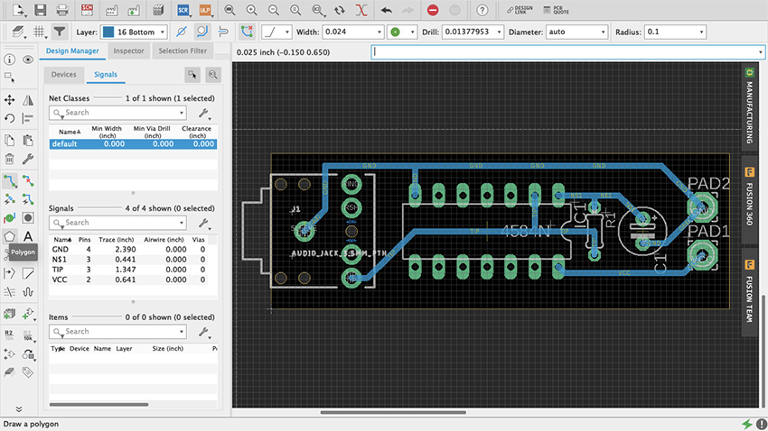
Figure 76 Polygon Tool
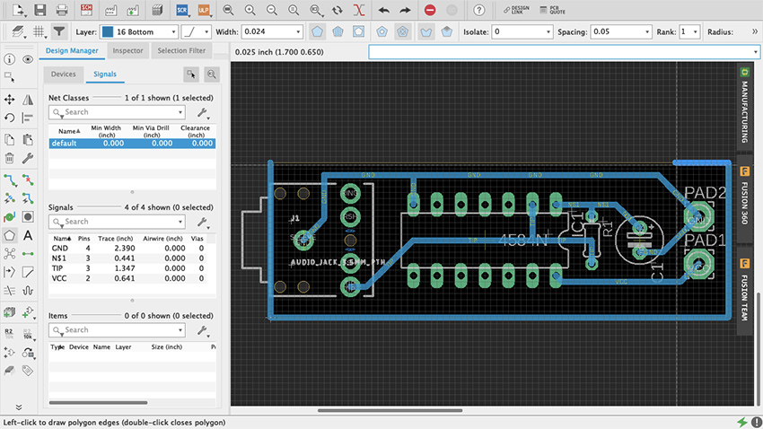
Figure 77 Polygon
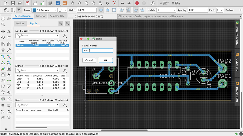
Figure 78 Signal Name Polygon
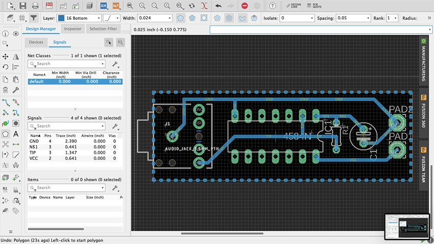
Figure 79 Dashed Polygon
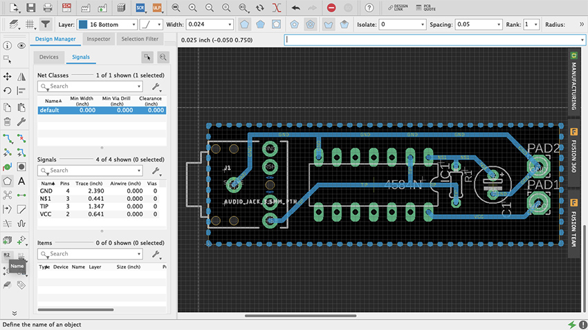
Figure 80 Name Command
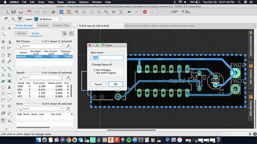
Figure 81 This Polygon
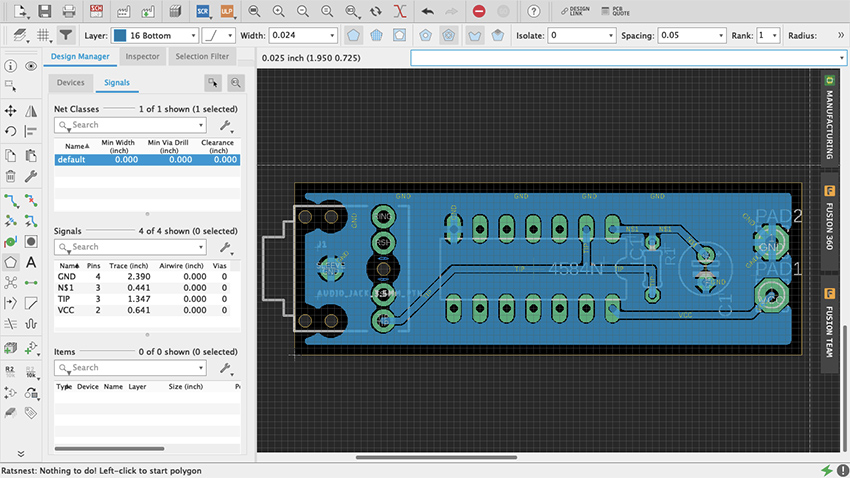
Figure 82 Copper Pour
Making boards
It’s good practice to print your board layout on paper once it is done, glue it on a styrofoam block, and do a mock-up version of the circuit to make sure that the parts are correct and that the spacings are adequate (thank you Robert Drinkwater!). It is no fun to find yourself fixing every hole on the board with a pin vise because they were too small; or learning that the legs of your switch do not match the part that was used as a template for the design. If everything fits alright on paper, then we can fabricate a prototype.
There are three option when it comes to making your own boards: etching, milling and manufacture. Etching will not be covered on this chapter – despite its old-school cred (think Robert Moog’s 1950s Theremin kits) -- because improperly disposed ferric oxide will not only ruin your sink and plumbing, but is also a serious environmental hazard and is illegal to throw out. The other two approaches are safer.
Milling PCBs
Milling boards is a fast and reliable way of prototyping your designs before manufacturing them by the hundreds through a commercial house. It can be sufficient to produce a handful of boards for yourself and your friends. For this example, I will focus on Bantam Tools Desktop PCB Milling Machine, a CNC machine. Although at the time of writing still a little pricey for the amateur hacker, they are popping up in art schools and maker spaces. Ask around, but if for any reason milling is not an option, jump ahead to the next section on board houses.
The first thing to do is download Bantam’s milling machine software to communicate with the mill and setup your project. You find it at bantamtools.com/software-download. Install the application and launch it. The software is simple and fairly intuitive. In the center of your computer screen you should see the bed of the machine and a blue block, which is your generic material (figure 83). Zooming out enough will reveal an opaque image of the mill (figure 84). Above, different views are available: front, top and 3D; as well as preview and toolpath options. On the right are the configuration settings for your project. Connect the mill to your computer. Locate the bed.
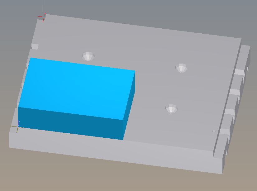
Figure 83 Bantam Material
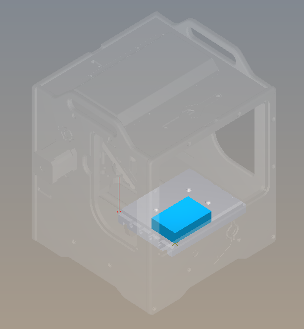
Figure 84 Bantam Machine
Printed circuit boards are made of different materials. FR-4, made of fiberglass and epoxy resin, is probably the most common, but because of the fiberglass, machining FR-4 is dangerous for your health. Instead we are going to use FR-1, made with phenolic resin, which is safer (but nonetheless avoid ingesting, inhaling or getting it in your eyes). FR-1 can be acquired from many sources, including Bantam but also SparkFun and Digi-Key. On Bantam’s Material dropdown menu select Single-Sided FR-1. On the Material dropdown menu select Single-Sided FR1. Immediately the generic blue block turns into a copper board. If the board you have has different measurements, adjust the width and the height on the Size menu. I recommend leaving the default value thickness. Using thin double-sided tape, place your board on the mill’s bed and against the guides. The tape is just so that the board is stable while the machines works. Do no use anything thicker than scotch tape.
Import your design from your EDA (Fritzing, Eagle, etc.) into Bantam by clicking on the open button on the Plans section. Bantam supports many different file formats but we will use “.brd.” The design layout will appear on the board and can be moved within the boundaries. Use the placement menu to indicate the location and orientation. Leave small distance between the design and the guides for the safety of the drill bit.
In Milling Tools select the sizes of the bits that you will be using. If two traces are too close for the bit diameter, red marks will show on the design. You can try different milling tools, or the traces can be adjusted in Eagle and refreshed on Bantam so that the changes are reflected. Whenever possible use just one tool for the whole job, it’s easier. Below the Start Milling button is an estimate of how much time will it take to mill the board. Under Advance, both the depth and clearance of the traces can be adjusted. Remember that milling too deep may result in a fragile board and also the bit will become dull faster. Too much clearance will increase the turnaround time considerably, and also will make the bit dull faster.
Once your setup is ready click Mill All Visible. The machine will ask for you to insert the new tool. After tool is in place the mill “locates” the tool by touching the bed. Then milling starts.
When the board is ready, carefully—you don’t want to snap it—lift it off the bed. Before soldering the components in place, take the time to check and clean the board. Make sure that there is no copper residue shorting the circuit.
Assemble the board carefully. FR1 boards will allow for maybe one soldering mistake before the copper burns or peels off.
Manufacturing
Getting a board design manufactured requires that the files are submitted that comply with the board house’s specifications. There are hundreds of manufacturers, and although the process is fairly standardized, requirements often differ from one to another. Failing to adhere to the appropriate spec may result in mistakes, or the board not being produced at all. Eagle makes it very easy to generate the necessary manufacturing files. These are Gerber (.gbr) files which include copper, soldermask and silkscreen, among other layers; and Excellon (.xln) for your drill files.
Some manufacturers, such as OSH Park, accept Eagle’s .brd files so you don’t need to generate additional files. Nonetheless, you should import their Design Rule files and check your design. Go to docs.oshpark.com/design-tools/eagle/design-rules-files/ and download the .dru file for either 2 or 4-layer boards. Then, on Eagle, go to Tools > DRC > Load and select the .dru file that you just downloaded for your project. Now when you do a Design Rules Check, Eagle will use OSH Park’s specifications.
You might work with various board houses, so knowing how to produce the necessary files is important. First, open up the CAM processor, which is at the top on the board editor and looks like a factory with three windows (figure 85). CAM stands for computer-aided manufacturing. This new menu is divided into a few different parts (figure 86). On the upper-left corner a bar will tell what kind of CAM job will be produced. The default for our version of Eagle is a 2-layer template. If you click on the paper sheet icon next to it, a drop-down menu will offer additional options (figure 87).
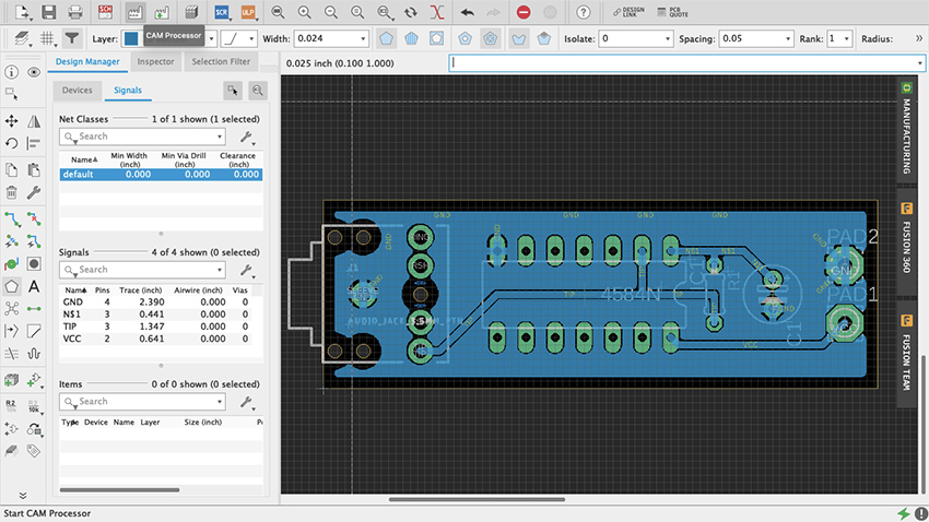
Figure 85 Eagle CAM Processor
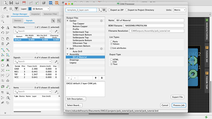
Figure 86 Menu CAM Processor
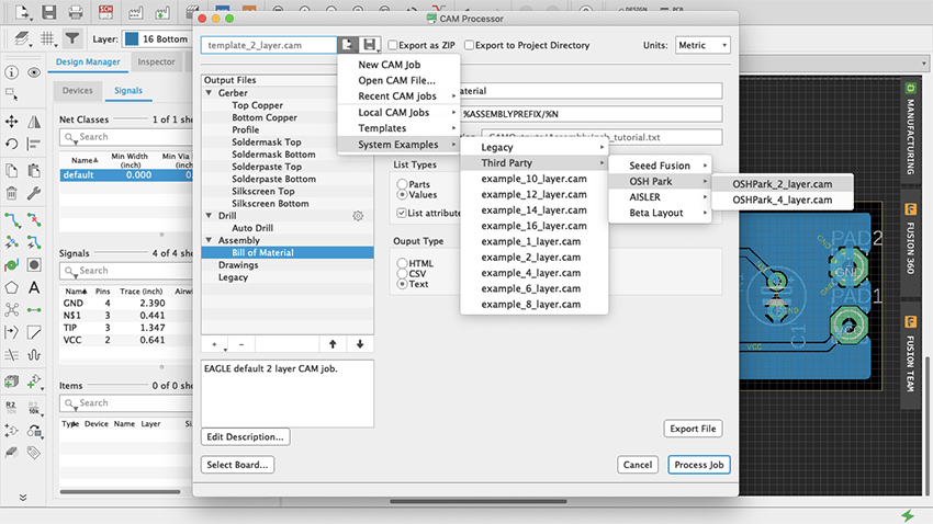
Figure 87 CAM Job Templates
On the left the Output Files section lists all the different types of files and their contents. For example, when one of the Gerber files is selected, its contents will be made visible as a list in the Layers panel, along with a graphic representation of those layers (figure 88). Two check-boxes for board shape and cutouts are available to include on each of the files. These can prove useful for aligning and assembly, but check with your board house specs if it is necessary to do so.
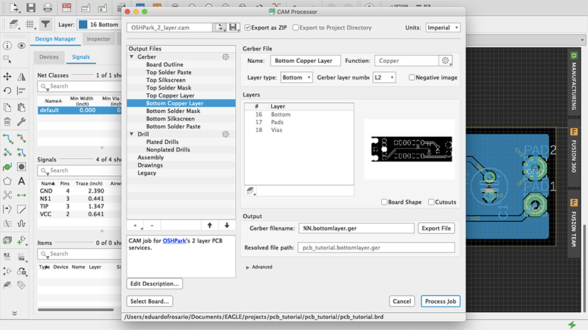
Figure 88 Output Files
Before exporting anything click on “Gerber” in the Output Files section, and on Options the default should be either Gerber RS-274X or the newer format Gerber X2. Gerber X2 is backwards compatible and will work with any board manufacturer. All files will be exported when Process Job is clicked. Individual files can be obtained by using the Output bar below the Layers section: select the layer you want and click Export File.
A good way to start production is to use the third-party CAM job files included with Eagle. Press Load Job File—which is the paper sheet icon with an arrow pointing to the right—then at the bottom select System Examples > Third Party and in there you will find Seeed, OSH Park, Aisler and Beta Layout CAM job files for 2, 4 and even 6-layer boards. All these manufacturers offer professional PCB services for reasonable prices and a prompt turnaround. There is no need to produce 100 boards of a design that has not been tested out. An order can be placed with OSH Park—for example—for as little as 3 boards. This way economic risk—and e-waste—is reduced significantly when a project is still in its development phase. Eagle is not the only EDA that offers CAM templates. Fritzing is also affiliated with Aisler, or you can ask your board house of preference whether they have .dru file and/or CAM Job templates. There are manufacturers all over the world and there is no need to stick to these specifically. If another PCB manufacturer is particularly convenient because of location or any other reason, contact them and request their specifications. Once everything’s setup the way you want it on the CAM Processor, click Process Job (figure 89, 90) and all the files will be saved in a .zip file ready to be sent to the board house.
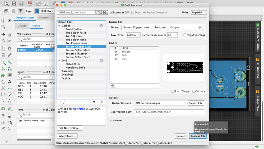
Figure 89 Process Job
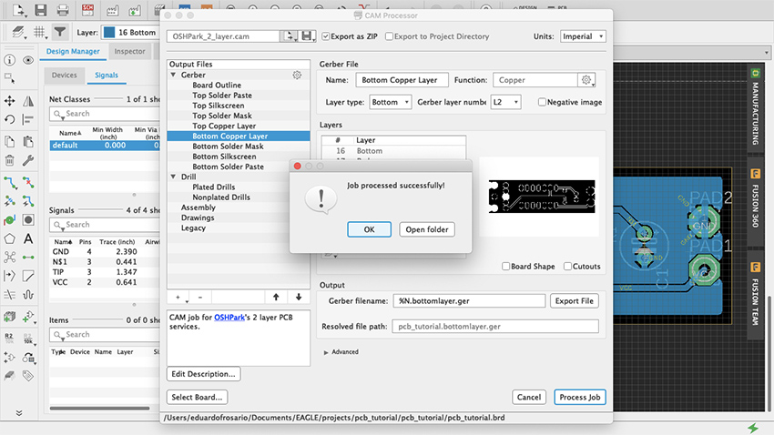
Figure 90 CAM Job Successful
Going forward, a good thing to explore is how to make new parts in Eagle. This is not difficult. You can start by duplicating and modifying an already existing part to suit your needs. Parts are made of a symbol and a package, they meet to form a device that lives in your parts library. You can find many step-by-step guides with a quick search online. Understanding how parts are made can shed some additional light on the best way to develop your designs, and which parts to choose from the vast libraries. Unlike Fritzing, Eagle doesn’t have a Breadboard view. But because there are 3D models of many of the parts in the library, a design can be imported into Fusion 360 to do further work on it.
Microcontroller Sound (Joseph Kramer)
Data files for chapter 33
Download Arduino (ZIP 113KB) Download Fritzing (ZIP 198KB)
Microcontroller Sound (Joseph Kramer): Additional projects
Circuit Two: Pseudo-analog effects, tones without delay, and notes quantized to scales.
Overview
The following circuit expands on the digital oscillators described in the book by adding a second knob and a volume control (via a light-dependent resistor paired with an LED). By controlling the brightness of the LED using pulse width modulation (PWM), intermediate volume levels can be achieved. The basic principle is explored in the first sketch, then expanded in the second sketch using the tone() function. Arrays are introduced in the third sketch, allowing for the playback of pre-programmed melodies with dynamic volumes. Finally, a simple quantizer is created to constrain notes performed via knob turns to desired scales.
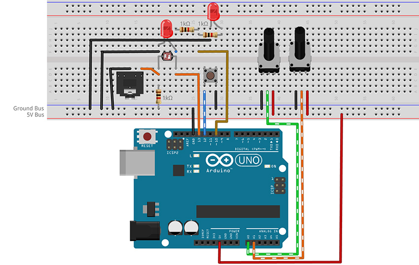
Figure 3 - Fritzing breadboard image of digital oscillator with volume control circuit
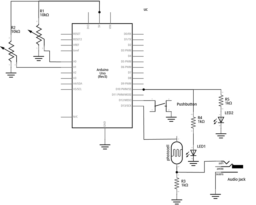
Figure 4 – Fritzing schematic of digital oscillator with volume control circuit
You will need:
- An Arduino Uno.
- A computer running the Arduino IDE software.
- A USB cable that can connect from your computer to the Uno’s USB type-B connector.
- A breadboard.
- Some solid hookup wire or premade wire jumpers.
- Assorted resistors (1kΩ – 100kΩ is a good range).
- A 10kΩ linear potentiometer.
- A pushbutton or toggle switch.
- Some photoresistors.
- Some LEDs (Light Emitting Diodes).
- An audio amplifier.
- Assorted jacks and plugs, to match your amplifier.
- Hand tools.
Connect the Hardware
- Open Fritzing File and navigate to Breadboard view
- Insert all components into breadboard matching the image
- Connect all wires on breadboard
- Connect wires from Arduino to breadboard
- Visually double-check all connections and wiring
- Connect the Arduino Uno to your Computer
Project One: Volume Control
Program the Arduino with the VolumeOSC sketch.
- Open the Arduino sketch
- Click the upload button near the top left of the sketch window
//CODE HEM_VolumeOSC ******

								int tonePin = 13;      //create a variable to represent LED Pin

								int buttonPin = 12;   //add variable for the button pin

								int volLED = 10;      //add variable for the Volume LED

								int periodKnob = A0;  //add variable for knob pin (A = analog in)

								int volumeKnob = A1;  //add variable for knob pin (A = analog in)

								int delayTime;        //create a variable for the delay time

								int fadeVal = 0;      //create a variable to store the brightness of the LED
								void setup() {

								  pinMode(tonePin, OUTPUT); //configure pin 13 as an output

								  //INPUT_PULLUP sets the pin high. It gets pulled "low" by

								  //connecting it to ground through a button

								  pinMode(buttonPin, INPUT_PULLUP);

								}
								void loop() {

								  //set delay time equal to the current value read on analog pin 0

								  delayTime = analogRead(periodKnob);


								  //map the analog read range from 0 - 1023 to 10000 to 1

								  delayTime = map(delayTime, 0, 1023, 10000, 1);


								  digitalWrite(tonePin, HIGH);

								  delayMicroseconds(delayTime);

								  digitalWrite(tonePin, LOW);

								  delayMicroseconds(delayTime);

								//check the button. It will be LOW if pressed

								  //If the button is pressed, write fade value to the LED:

								  if (digitalRead(buttonPin) == LOW) {

								    //read the fade knob and scale the range from

								    //10bits (0 - 1023) to 8 bits (0 - 255)

								    //analogRead is 10 bits

								    //analogWrite is 8 bits

								    //1023 divided by 4 is 255 (faster than map())

								    fadeVal = analogRead(volumeKnob) / 4;

								    analogWrite(volLED, fadeVal);

								  }
								else {

								    //turn LED off if button not pressed

								    analogWrite(volLED, 0);

								  }
								}

								//**********END OF CODE
What's Happening?
This sketch provides a method for creating analog-like effects using a technique called Pulse Width Modulation (PWM). This is done with the analogWrite() function, but is (confusingly) only possible on the digital pins. This is because, technically, PWM is still a digital signal. PWM works by toggling a pin high and low at a fixed frequency while adjusting the percentage of time that the wave is HIGH versus the time it is LOW in order to deliver less current than if the pin were just held at a constant HIGH level. This allows the LED to be set to intermediate levels of brightness between all the way ON (analogWrite(pin, 255) - PWM signal is HIGH 100% of the time), to a medium brightness (analogWrite(pin, 128) - PWM signal is HIGH 50% of the time), to all the way off (anlaogWrite(pin, 0) - PWM signal is HIGH 0% of the time). Take note that not all of the digital pins can generate PWM. Only the six pins with the tilde (~) symbol next to them are capable of this function.
We are using PWM to control the brightness of two LEDs from one pin. One of the LEDs is used for visual feedback, while the other is paired with a photocell with the intent to control volume with light. The benefit of using PWM is that in addition to simple binary blinking, we are able to program the brightness level smoothly from fully bright to completely dark. When using this technique to control volume the effect can imperfect (you may hear some of the PWM frequency in your signal – this can be improved by using a different microcontroller with a higher PWM frequency), but with some finessing of the led-photocell pairings the technique opens up fruitful avenues of experimentation.
This sketch uses a button and two knobs to control the activation, pitch, and loudness of an oscillator. The knob on pin A0 controls the pitch by setting the period of the waveform via the delayMicroseconds() argument. (This method of sound generation is described in an earlier project.) When the button is pressed, the knob connected to pin A1 sets the brightness of the LED in the photocell/LED pair. This brightness controls the volume of the oscillator via the voltage divider created by the photocell and fixed resistor pairing. When the button is released, the LED turns off and the note fades out at the photocell’s response speed. You may need to experiment with the value of the fixed resistor (1kΩ in the example) to get the best response from your photocell. (It may be useful to start with a potentiometer in place of the 1kΩ fixed resistor to dial in the value that works best for your photocell/LED pair. The technique for using a potentiometer to determine the value of a fixed resistor is described in the book.)
If your photocell causes a fade out due to a slow response time then you are likely to notice that the pitch of the oscillator changes when the button is released. This happens because the tone is generated by pausing at points in the loop using delays. But delays are not the only things that the microcontroller has to do, and each instruction adds time between toggles. This means the frequency can be affected by how long it takes for the microcontroller to get through the other instructions in the loop. When the button is pressed, the if statement is engaged and more lines of code have to be executed by the microcontroller compared to when the button is not pressed. As a result, there is more time between the pin going LOW and the pin going HIGH again. This lowers the pitch of the microcontroller slightly when the button is down. One approach to stabilizing the frequency is to make sure that the if statement and the else statement take the same amount of time by moving some instructions out of that structure and into the main loop. But a better way to handle this issue would be to do away with thedelay() method of tone generation altogether and instead make use the tone() function built into the Arduino library.
Project Two: Volume Control with Improved Timing via tone()
Program the Arduino with the VolumeOSC_tone sketch.
- Open the Arduino sketch
- Click the upload button near the top left of the sketch window
//CODE HEM_VolumeOSC_tone ******

								int tonePin = 13;           //create a variable to represent LED Pin

								int buttonPin = 12;       //add variable for the button pin

								int volLED = 10;       //add variable for the Volume LED

								int periodKnob = A0;  //add variable for knob pin (A = analog in)

								int volumeKnob = A1;  //add variable for knob pin (A = analog in)

								int knobVal;               //create a variable for the delay time

								int fadeVal = 0;           //create a variable to store the brightness of the LED
								void setup() {

								  pinMode(tonePin, OUTPUT); //configure pin 13 as an output

								  //INPUT_PULLUP sets the pin high. It gets pulled "low" by

								  //connecting it to ground through a button

								  pinMode(buttonPin, INPUT_PULLUP);

								}
								void loop() {

								  //set variable knobVal equal to the current value read on analog pin 0

								  knobVal = analogRead(periodKnob);
								//map the frequency range from 0 - 1023 to 110 - 1760

								  int toneFreq = map(knobVal, 0, 1023, 110, 1760);
								tone(tonePin, toneFreq);
								//check the button. It will be LOW if pressed

								  //If the button is pressed, fade up the LED:

								  if (digitalRead(buttonPin) == LOW) {

								    //read the fade knob and scale the range from

								    //10bits (0 - 1023) to 8 bits (0 - 255)

								    //analogRead is 10 bits

								    //analogWrite is 8 bits

								    //1023 divided by 4 is 255 (faster than map())

								    fadeVal = analogRead(volumeKnob) / 4;

								    analogWrite(volLED, fadeVal);

								  }
								else {

								    //do nothing if button

								    analogWrite(volLED, 0);

								  }
								}

								//**********END OF CODE
What's Happening?
Using the tone() function eliminates the need to employ the delay() function for our audio task. This has the benefit of freeing our loop to do other things without interference. To start a note using tone() we will call the function and pass it two arguments: which pin, and what frequency. If we want stop the tone, we can call the complementary function noTone() which will take one argument to clarify which pin to silence. The tone() function can produce frequencies from about 31Hz to nearly 5kHz. The map() function is used here to select a range from 110Hz to 1760Hz. These numbers were chosen by ear and can be adjusted to taste. For more ways to use tone() see the built-in examples at File>Examples>Digital>[…].
Keeping the audio generation free of delays frees us to do useful things in the rest of the loop without affecting the pitch of the oscillator. Examples of useful things might include blinking lights, reading sensors, moving through sequences of notes, etc. This circuit and tone() function are expanded to function as a simple note sequencer in the next project.
Project Three: Stored Melodies with Dynamics
Program the Arduino with the ToneSEQ sketch.
- Open the Arduino sketch
- Click the upload button near the top left of the sketch window
//CODE HEM_ToneSEQ ******

								int ledPin = 13;      //create a variable to represent LED/tone pin

								int buttonPin = 12;   //add a variable for the button pin

								int volLED = 10;      //add variable for the Volume LED (must have PWM)

								int periodKnob = A0;  //add variable for speed knob pin (A = analog in)

								int delayTime;        //create a variable for the delay time

								int stepKnob = A1;    //add variable for step number knob pin

								int stepNum = 7;      //this is the number of steps the sequencer will play

								int seqNum = 0;

								byte i = 0;        //i is used to count up through the arrays
								//create an array to store volumes

								int thisVol[8] =

								{255, 128, 0, 10, 4, 15, 6, 50};
								//create a 2D array to store frequencies

								int thisTone[2][8] = {

								  {880, 41, 33, 494, 659, 1047, 62, 73},

								  {41, 33, 33, 494, 247, 880, 880, 73}

								};
								void setup() {

								  pinMode(buttonPin, INPUT_PULLUP);

								}
								void loop() {

								  //read the step knob to determine how many steps should be played

								  //0 is the first item and 7 is the last item in the array

								  stepNum = map(analogRead(stepKnob), 0, 1023, 0, 7);
								  //check to see if we are at the end of the array, if so

								  //start over at 0

								  if (i > stepNum) {

								    i = 0;

								  }
								  //the array of notes is a two-dimensional array; it is a list

								  //of different lists.

								  //we read the button to determine which of the two lists

								  //to get our note values from

								  if (digitalRead(buttonPin) == LOW) {

								    seqNum = 1;

								  }
								  else {

								    seqNum = 0;

								  }
								  //tone plays a tone based on one of the two arrays defined above

								  //seqNum will be 0 or 1 depending on the button state, 0 plays the

								  //first list of numbers, 1 plays the second

								  //i determines which note in the selected list: 0 is the first, 1

								  //is the second, 2 is the third...7 is the last one, then i resets

								  tone(ledPin, thisTone[seqNum][i]);
								  //the led controlles the volume based on brightness

								  //it just has a single array of possibilities, but it could

								  //have two different lists just like thisTone

								  analogWrite(volLED, thisVol[i]);
								  //read the knob and change the direction without using map()

								  delayTime = 1023 - analogRead(periodKnob);

								  delay(delayTime); //let the note continue while the program pauses

								  noTone(ledPin);   //turn off the current note

								  i++;             //this adds one to i (increment by one).

								}

								//**********END OF CODE
What's Happening?
This sketch makes use of iteration and arrays.
We created this list of tones in a data structure called and array. The array is declared at the start of the code just like any other variable. Start by writing the data type, followed by a space and then a name of our choosing. This name is followed immediately by brackets enclosing a number that represents how many items will be in our array. If the number in the brackets is 16, then we would follow that with a list of 16 values, separated by commas, and enclosed in curly braces. End the line with a semicolon.
To access a value from the list, type the name of the array with the number of the item in the brackets. This is known as the index of the array. Note that counting starts at zero, so the index of the first value is 0, and the index of the last item is the number of items minus one. We use the variable “i” to move through the list.
The variable “i” is used in this case to keep track of which number to pass the tone() function from a list of tones. We iterate, or count up through the list, by adding one to the variable “i” each time we go through the loop. (i++;) When we get to the last numbered item, we reset “i” to zero to start again at the beginning of the array.
										if (i > stepNum) {

										    i = 0;

										  }
The list of volumes is stored in a simple array. This is a list of PWM values between 0 – 255 used to control the brightness of an LED. The list of tones, called “thisTone[][]” in the code, uses a two-dimensional array. This allows us to pick our notes from one of two lists in order to allow for alternate melodies. The array has two sets of brackets which can be thought of as representing rows and columns, respectively. A number in first bracket will select the row, or which list to play tones from. A number in the second bracket will select which tone to play from the selected list. The numbers in the lists represent the rough frequencies of different pitches. For a list of the pitches see the example files in Arduino at File>Examples>02.Digital>toneMelody. There is a second tab in that sketch window called pitches.h which lists available values. Alternatively, search the internet for the frequencies of musical notes.
To play the notes, call the tone() function and provide it with two arguments: which pin to play the tone on, and what frequency to play. Calling the following line of code will play 880 (note A5), the first tone from the first list:
tone(ledPin, thisTone[0][0]);
To play the tone 659 (E5), the 5th item on the 1st list, you would call:
tone(ledPin, thisTone[0][4]);
There are only two built-in sequences in this array, but you can experiment with adding more. To create a third list, simply change the number in the first bracket of the variable declaration at the top of the code from 2 to 3 and create a new list of numbers. Here is an example:
//create an array to store frequencies

									int thisTone[3][8] = {

									  {880, 41, 33, 494, 659, 1047, 62, 73},

									  {41, 33, 33, 494, 247, 880, 880, 73},

									  {659, 1047, 1047, 1047, 659, 1047, 1047, 1047},

									};
This simple sequencer has many possible variations and could be used to code longer melodies or even entire songs. Another avenue of experimentation would be to lose the notes entirely and only keep the volume control. Connecting an audio jack to the photocell volume control instead of the internal oscillator would allow for the creation of a programmable audio slicer. Alternatively, the note arrays could be kept, but the stepping function removed and the code revised to play tones and volumes selected by knobs or some other novel controller. For example, a quantized Theremin-like instrument could be created using distance sensors to select pitches and volumes. The next example will walk through the creation of a simple tone quantizer.
Project Four: Quantizer for Digital Oscillator
Program the Arduino with the ToneQUANTIZER sketch.
- Open the Arduino sketch [link]
- Click the upload button near the top left of the sketch window
//CODE HEM_ToneQUANTIZER******

									const int tonePin = 13;      //create a variable to represent LED Pin

									const byte buttonPin = 12;   //add variable for the button pin

									const byte volLED = 10;      //add variable for the Volume LED

									const byte noteKnob = A0;  //add variable for knob pin (A = analog in)

									const byte scaleKnob = A1;  //add variable for knob pin (A = analog in)

									int knobVal;        //create a variable for the delay time

									int scaleType;      //create a variable to store the desired scale

									int fadeVal = 0;      //create a variable to store the brightness of the LED
									int degreeIndex;

									byte octave = 3; //can be made variable by adding a knob

									byte root = 6;  //can be made variable by adding a knob (0 = B, 1 = C, 2 = C#, 3 = D ... 6 = F, etc)

									int i;  //variable to represent index of array
									const int chromaticScale[89] = {31, 33, 35, 37, 39, 41, 44, 46, 49, 52, 55, 58, 62, 65, 69, 73, 78, 82, 87, 93, 98, 104, 110, 117, 123, 131, 139, 147, 156, 165, 175, 185, 196, 208, 220, 233, 247, 262, 277, 294, 311, 330, 349, 370, 392, 415, 440, 466, 494, 523, 554, 587, 622, 659, 698, 740, 784, 831, 880, 932, 988, 1047, 1109, 1175, 1245, 1319, 1297, 1480, 1568, 1661, 1760, 1865, 1976, 2093, 2217, 2349, 2489, 2637, 2794, 2960, 3136, 3322, 3520, 3729, 3951, 4186, 4435, 4699, 4978};
									const byte chromaticMask[14] = {0, 1, 2, 3, 4, 5, 6, 7, 8, 9, 10, 11, 12, 13};

									const byte majorMask[8] = {0, 2, 4, 5, 7, 9, 11, 12};

									const byte minorMask[8] = {0, 2, 3, 5, 7, 8, 10, 12};

									const byte majorPentatonicMask[6] = {0, 2, 4, 7, 9, 12};

									const byte minorPentatonicMask[6] = {0, 3, 5, 7, 10, 12};
									const byte tonicMask[] = {0, 1, 2, 3, 4, 5, 6, 7, 8, 9, 10, 11};

									const byte octaveMask[] = {0, 12, 24, 36, 48, 60};

									byte pitchNum;   //variable to store the index of the note array

									int note = 0;
									void setup() {

									  pinMode(tonePin, OUTPUT); //configure pin 13 as an output

									  //INPUT_PULLUP sets the pin high. It gets pulled "low" by

									  //connecting it to ground through a button

									  pinMode(buttonPin, INPUT_PULLUP);

									}
									void loop() {

									  //set variable knobVal equal to the current value read on analog pin 0

									  knobVal = analogRead(noteKnob);

									  scaleType = analogRead(scaleKnob);
									  int scale = map(scaleType, 0, 1023, 0, 4);
									  if (scale == 0) {

									    i = map(knobVal, 0, 1023, 0, 12);

									    degreeIndex = chromaticMask[i];

									    pitchNum = octaveMask[octave] + degreeIndex + tonicMask[root];

									    note = chromaticScale[pitchNum];

									  }
									  if (scale == 1) { //B Major Scale

									    i = map(knobVal, 0, 1023, 0, 7);

									    degreeIndex = majorMask[i];

									    pitchNum = octaveMask[octave] + degreeIndex + tonicMask[root];

									    note = chromaticScale[pitchNum];

									  }
									  if (scale == 2) {

									    i = map(knobVal, 0, 1023, 0, 7);

									    degreeIndex = minorMask[i];

									    pitchNum = octaveMask[octave] + degreeIndex + tonicMask[root];

									    note = chromaticScale[pitchNum];

									  }
									  if (scale == 3) {

									    i = map(knobVal, 0, 1023, 0, 5);

									    degreeIndex = majorPentatonicMask[i];

									    pitchNum = octaveMask[octave] + degreeIndex + tonicMask[root];

									    note = chromaticScale[pitchNum];

									  }
									  if (scale == 4) {

									    i = map(knobVal, 0, 1023, 0, 5);

									    degreeIndex = minorPentatonicMask[i];

									    pitchNum = octaveMask[octave] + degreeIndex + tonicMask[root];

									    note = chromaticScale[pitchNum];

									  }
									  //check the button. It will be LOW if pressed

									  //If the button is pressed, write fade value to the LED:

									  if (digitalRead(buttonPin) == LOW) {

									    tone(tonePin, note);

									    analogWrite(volLED, 255); //turn the volume all the way on and play the note

									  }
									  else {

									    //do nothing if button

									    analogWrite(volLED, 0);

									  }
									}

									//**********END OF CODE
What's Happening?
What you should observe is that pressing the button causes the light to turn on and a note to be played. Releasing the button turns off the LED and silences the note. Turning the note knob (on pin A0) will cause the pitch of the note to change. Rotating the knob from one end to the other will play through the entire selected scale. Turning the second knob will change the type of scale that is selected. In this example, the scales are chromatic, major, natural minor, major pentatonic, and minor pentatonic. (Though many other scales are possible.)
A quantizer takes a set of incoming values and maps them to a desired set of outgoing notes. In this case, the incoming values are just a range of numbers that result from our program reading a knob (the 10-bit analogRead() reports a range of numbers between 0 – 1023). The desired outgoing notes of our quantizer will be selected from a list of frequencies belonging to the same musical scale. These frequencies will be passed to the tone() function. It is a bit like sliding one’s finger across only the white keys of a piano to play C major. Only this implementation of a quantizer is able to select from a large number of different keys and scales.
To understand how this is accomplished, we will start by examining the tone() function. As discussed in previous examples, the tone() function takes two arguments: 1. which pin to play the tone on, and 2. the frequency of the tone to produce. The frequencies that the function can produce are limited to the relatively wide range of 31Hz (note B0) to 4,978Hz(D#8). When tone() was used in previous examples, a knob was read and the value (0 – 1023) was mapped to some desired range within that 32 – 4987 Hz limit. Consider the following code fragment:
										int rawNote = analogRead(noteKnob);

										int frequency = map(rawNote, 0, 1023, 31, 4978);

										tone(tonePin, frequency);
With this example, turning the knob would result in a relatively smooth slide between pitches, with many octaves being moved through on the low range of the knob, and only about one high octave spread across the whole right-hand side of the knob. This is pretty classic oscillator behavior and certainly great fun, but it can be pretty difficult to play a specific note.
To spread the frequencies more evenly across the knob range, and only play notes that roughly correspond to notes in Western music, an array is defined. The first array, chromaticScale[89], is a large list of every possible note in 12-tone equal temperament that the tone() function is capable of producing. There are 89 frequencies in the list that correspond nearly, but not exactly, to the frequencies of the notes on a standard modern piano. (The range of a grand piano is very slightly different, and most notes in Western music have frequencies with decimal point components which tone() is not capable of producing.) If all we wanted was a chromatic scale, we could simply read an analog input and scale the result from the analogRead range of 0 – 1023 to the chromaticScale[89] range of 0 – 88 using the map() function. Using the output of that map function as the index of the chromaticScale[89] array would allow us to directly select from that list of notes. The code fragment below would quantize our oscillator to only play notes from the chromatic scale:
										int rawNote = analogRead(noteKnob);

										int pitchNum = map(rawNote, 0, 1023, 0, 88);

										note = chromaticScale[pitchNum];

										tone(tonePin, note);
It would be possible to just hard code arrays for every possible scale we wanted to play, but it would be impractical to create such lists for all desired scales. To accommodate a more flexible system that can be used to select different scale types (like major, minor, pentatonic, etc) and different tonics (for example A, Bb, F#, etc) this example implements a set of masks. These masks are arrays of index values for given scales, and offsets for given tonics and octaves. The numbers in the majorMask[ ] array, for example, contain the index values for the first octave of the B major scale if applied directly to the chromaticScale[ ] array. The tonicMask[ ] is a bit unnecessary as it is a simple sequence, but it would allow for more flexible access to the notes if a different system was desired.
Our first scale, the chromatic scale, is the easiest to understand as it just plays through each possible note, starting with the root and ending with the root an octave above. So to play one octave of a chromatic scale in the key of B, we just need to pass the chromaticScale[89] array an index value from 0 – 12. If we wanted to shift the root from B to C in order to play a C scale, we would just add one to each item in the index, causing the output to play notes 1 – 13. If we wanted to shift to a root of F, we would add 6 (notes 6 – 18). The code fragment below would play one octave of the F chromatic scale:
										int root = 6;

										int rawKnob = analogRead(noteKnob);

										int degreeIndex = map(rawKnob, 0, 1023, 0, 12);  //this maps the knob so it only reads one octave of

										pitchNum = degreeIndex + root;

										note = chromaticScale[pitchNum];

										tone(tonePin, note);
In this case, our knob gets mapped to a variable with a range of 0 – 12, and the instruction pitchNum = degreeIndex + root; just adds a 6 to each degreeIndex value. pitchNum is then used as the index of the chromatic scale array. This causes the notes that get played to be shifted up in the list by 6. This simple mechanism allows us to use the one large list of notes to generate a chromatic scale of any number of octaves starting at any note.
To get a different octave, we can add an octave mask. New octaves are 12 index values apart. So, if we want to start on the first octave, we add an offset to the index of zero. For the next octave, we add an offset of 12. Next, an offset of 24, and so on. We can add the octave offset as follows:
										cost byte octaveMask[] = {0, 12, 24, 36, 48, 60};

										int root = 6;

										int octave = 2;

										int rawKnob = analogRead(noteKnob);

										int degreeIndex = map(rawKnob, 0, 1023, 0, 12);  //this maps the knob so it only reads one octave of

										pitchNum = octaveMask[octave] + degreeIndex + root; //this gives the octave, scale degree and root

										note = chromaticScale[pitchNum];

										tone(tonePin, note);
Try different values of root and octave to hear different chromatic scales at different octaves. You can also try adding knobs to directly select the octave and the root by reading knobs and mapping their values to desirable ranges.
The second knob in this example, however, is used to select from a set of 5 different scale types. Each of these scale types has a unique mask that can be used to pick appropriate notes from the main chromatic scale array using the simple shifting and masking techniques described so far.
Using the example of a C major scale to illustrate how this works may help circumvent too much discussion about music theory (though a thorough understanding of that subject may help with comprehension and expanding the available scale types). The C major scale starts on the note C and only includes the white keys. The index values of the white keys starting on C are 1, 3, 5, 6, 8, 10, 12, and 13 brings us back to C. (figure 2)
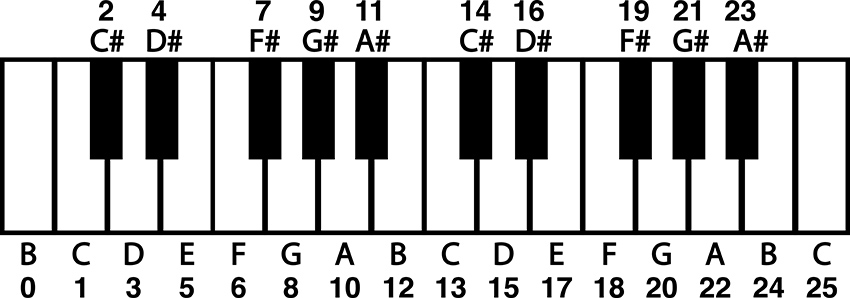
Figure 5 – Piano keyboard with note names and index values
To make a mask for C Major, we would simply use those numbers as the index of our chromatic scale array. To use a knob to play through the first octave of C Major, we could use the following code fragment:
										const byte octaveMask[] = {0, 12, 24, 36, 48, 60};

										const byte cMajorMask[8] = {1, 3, 5, 6, 8, 10, 12, 13};

										int octave = 2;

										int rawKnob = analogRead(noteKnob);

										int i = map(rawKnob, 0, 1023, 0, 7);  //note, only 8 notes in one octave of a major scale

										int degreeIndex = cMajorMask[i];

										pitchNum = octaveMask[octave] + degreeIndex; //this gives the octave, scale degree and root

										note = chromaticScale[pitchNum];

										tone(tonePin, note);
It would again be impractical to make a mask for every possible major scale at every tonic. So, we need to adjust this mask to make it usable for major scales starting on any note. To do that, we need to make the mask start at zero. That way the scale with a root of C is accessed by using the degree index plus a root offset of 1. So, if we subtract one from each item in the array, we get a major scale mask that starts at zero and can be offset to start at any note by changing the root value, just like the chromatic scale mask in the previous illustration. The resulting fragment will play a C major scale at the third octave. Change the root and octave to hear other major scales.
										const byte octaveMask[] = {0, 12, 24, 36, 48, 60};

										const byte majorMask[8] = {0, 2, 4, 5, 7, 9, 11, 12};

										int root = 1;

										int octave = 2;

										int rawKnob = analogRead(noteKnob);

										int i = map(rawKnob, 0, 1023, 0, 7);  //note, only 8 notes in one octave of a major scale

										int degreeIndex = majorMask[i];

										pitchNum = octaveMask[octave] + degreeIndex + root; //this gives the octave, scale degree and root

										note = chromaticScale[pitchNum];

										tone(tonePin, note);
The rest of this code establishes arrays for alternative scales and uses if statements to select from among the scales and respond to button presses. For more info on how if statements work, see earlier examples or check out the documentation built into Arduino’s IDE and on the web.
This quantizer is a useful proof of concept and can be included in other projects to make flexible and performable interfaces. Quantizers can be particularly useful when connecting the microcontroller hardware to other digital instruments using MIDI (Musical Instrument Digital Interface). MIDI divides the frequency space into MIDI note numbers, which can be packed up in array and called using the same basic mechanism described here.
Circuit Three: Four Digital Outputs for Rhythm Generation and Noisy Swarms
Overview
The following circuit creates four individual patterns of pulses visualized by four LEDs. Different patterns can be selected for the four channels using a potentiometer. The speed of the blinking is controlled by a second potentiometer and the length of the individual blinks are controlled by a third. These four channels are attached to four 1/8” output jacks that can be connected to other circuits to be used as gate signals (0v - +5V range) or connected to a mixer and used as linked polyphonic audio channels.
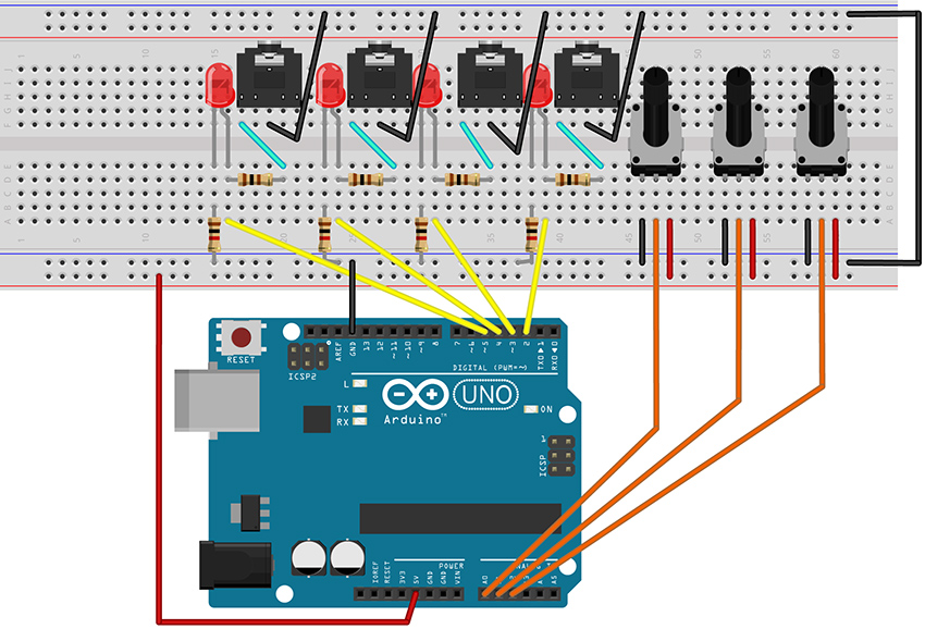
Figure 6 – Fritzing breadboard image of rhythm generation circuit
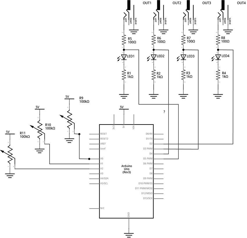
Figure 7 – Fritzing schematic of rhythm generation circuit
You will need:
- An Arduino Uno.
- A computer running the Arduino IDE software.
- A USB cable that can connect from your computer to the Uno’s USB type-B connector.
- A breadboard.
- Some solid hookup wire or premade wire jumpers.
- At least 4 100Ω resistors and at least 4 1kΩ resistors
- At least 4 LEDs (Light Emitting Diodes).
- An audio amplifier.
- Some kind of circuit that can respond to 5-volt gates/triggers.
- Assorted jacks and plugs, to match your amplifier.
- Hand tools.
Connect the Hardware
- Open Fritzing File [link] and navigate to Breadboard view
- Insert all components into breadboard matching image
- Connect all wires on breadboard
- Connect wires from Arduino to breadboard
- Visually Double-check all connections and wiring
- Connect the Arduino Uno to your Computer
Project Five: Quad Gate Generator
Program the Arduino with the QuadGATES sketch.
- Open the Arduino sketch [link]
- Click the upload button near the top left of the sketch window
									////////////

									//This code generates four patterns of 16 beats each.

									//LEDs blink to indicate the patterns of voltage.

									//1/8-inch jacks allow the signals to be used as gates or triggers

									//in an extended modular system.

									//

									//Knob 1 controls the master clock

									//Knob 2 picks from the preset patterns

									//Knob 3 sets the length of the triggers/gates - turning the knob all the way up creates ties

									//

									//The code is written so that each gate channel’s pattern number and trigger length can be

									//changed independently. Additional knobs would provide more variety and performance control.

									//For example, instead of one knob selecting the pattern number for all four channels, each of four

									// knobs can select the pattern number of a single channel, allowing for mixing patterns

									//////////////
									//The following variable MUST be defined as a const because it is used as the size of an array.

									//using a dynamic variable in the array size is not possible

									//this type of variable is often written in all caps

									const byte PATTERN_COUNT = 5; //if you create more patterns, change this number
									//this variable is an unsigned long because it is going to keep track of milliseconds

									//it will get very large while the program is running.

									unsigned long counter = 0;  //variable to keep track of the time
									int beat = 0; //index variable to keep track of the current step in the 16-beat pattern
									const int out1 = 2; //variables for pin connections for the gate outputs

									const int out2 = 3;

									const int out3 = 4;

									const int out4 = 5;
									const int clockKnob = A0; //variables for pin connections to knobs

									const int patternKnob = A1;

									const int lengthKnob = A2;
									int stepTime;  //variables to keep track of the mapped knob values

									int patternNum;

									int trigLength;
									//2-dimensional arrays to keep track of several 16-beat patterns per gate channel

									//1 means set a channel HIGH, 0 means set a channel LOW

									bool gateOnePatterns[][16] = {

									  {1, 0, 0, 0, 0, 0, 0, 0, 1, 0, 0, 0, 0, 0, 0, 0},

									  {1, 0, 0, 0, 0, 0, 0, 0, 1, 0, 0, 0, 0, 0, 0, 0},

									  {0, 0, 0, 0, 1, 0, 0, 0, 1, 0, 0, 0, 0, 1, 0, 1},

									  {1, 0, 0, 0, 1, 0, 0, 0, 1, 0, 0, 0, 1, 0, 1, 0},

									  {1, 1, 1, 1, 1, 1, 1, 1, 1, 1, 1, 1, 1, 1, 1, 1}

									};
									bool gateTwoPatterns[][16] = {

									  {0, 0, 0, 1, 0, 0, 0, 0, 0, 0, 0, 1, 0, 0, 0, 0},

									  {0, 0, 0, 1, 0, 0, 1, 0, 0, 0, 0, 1, 0, 0, 1, 0},

									  {1, 1, 1, 0, 1, 1, 0, 0, 1, 1, 0, 1, 1, 0, 1, 1},

									  {0, 0, 1, 1, 0, 0, 1, 0, 0, 0, 1, 1, 0, 1, 1, 1},

									  {1, 1, 1, 1, 1, 1, 1, 1, 1, 1, 1, 1, 1, 1, 1, 1}

									};
									bool gateThreePatterns[][16] = {

									  {0, 1, 0, 0, 0, 0, 0, 0, 0, 1, 0, 0, 0, 0, 0, 0},

									  {1, 0, 1, 0, 1, 0, 1, 0, 1, 1, 1, 0, 1, 0, 1, 0},

									  {1, 0, 0, 0, 0, 0, 0, 0, 1, 0, 0, 0, 0, 0, 0, 0},

									  {1, 0, 1, 1, 0, 1, 1, 0, 0, 0, 1, 1, 0, 1, 1, 1},

									  {1, 1, 1, 1, 1, 1, 1, 1, 1, 1, 1, 1, 1, 1, 1, 1}

									};
									bool gateFourPatterns[][16] = {

									  {0, 0, 1, 0, 0, 0, 0, 0, 0, 0, 1, 0, 0, 0, 0, 0},

									  {1, 0, 1, 0, 1, 1, 1, 0, 1, 0, 1, 0, 1, 1, 1, 1},

									  {1, 0, 1, 0, 1, 0, 1, 0, 1, 0, 1, 0, 1, 0, 1, 0},

									  {0, 1, 0, 1, 0, 1, 0, 1, 0, 1, 0, 1, 0, 1, 0, 1},

									  {1, 1, 1, 1, 1, 1, 1, 1, 1, 1, 1, 1, 1, 1, 1, 1}

									};

									void setup() {

									  pinMode(out1, OUTPUT);  //set gate pins as outputs

									  pinMode(out2, OUTPUT);

									  pinMode(out3, OUTPUT);

									  pinMode(out4, OUTPUT);

									}
									void loop() {

									  //Read Knobs and store raw values

									  int clockRaw = analogRead(clockKnob);

									  int patternRaw = analogRead(patternKnob);

									  int lengthRaw = analogRead(lengthKnob);
									  //Scale Raw values to desired ranges using the map() function

									  stepTime = map(clockRaw, 0, 1023, 1000, 30); //set a clock from 1000ms between beats to 30ms (make the 1000 and 30 smaller for oscillator-like effects)

									  patternNum = map(patternRaw, 0, 1023, 0, PATTERN_COUNT - 1); //select from patterns numbered 0 - 4

									  trigLength = map(lengthRaw, 0, 1023, 5, stepTime); //select trig lengths from 5ms to a full beat length
									  //keep track of time with custom function: stepper()

									  stepper(stepTime);
									  //write outputs high and low with custom function: trigger()

									  trigger(1, patternNum, trigLength);

									  trigger(2, patternNum, trigLength);

									  trigger(3, patternNum, trigLength);

									  trigger(4, patternNum, trigLength);
									}
									  //master timer function keeps track of which beat to play and keeps a running timer

									  void stepper(unsigned long stepDur) {

									    static unsigned long previousTime = 0;

									    counter = millis() - previousTime;  //counter counts up from 0 to whatever the step time has been set to


									    if (counter >= stepDur) { //if the counter reaches the stepTime, do the following:

									      beat++;             //increment the beat by one

									      previousTime = millis(); //update previousTime to right now

									      if (beat > 15) {      //if the beat reaches 16, start over at 0

									        beat = 0;

									      }

									    }

									  }
									//Custom Function to produce triggers of different lengths

									//The switch structure looks for which Gate Output number ("out")

									//then assigns a pattern number(patternNum) from a 2D array

									//then keeps track of how long to keep the Gate HIGH by comparing the trigLength ("dur") to the current

									//time of the counter (which is updated each time through the loop by the "stepper()" function)

									void trigger(int out, int patternNum, int dur) {

									  switch (out) {

									    case 1: //if the first argument ("out") is "1", do the following:

									      //check to see if the counter is less than the note length

									      //AND (&&) that the pattern indicates a "1". If so, write the output HIGH to 5V

									      if (counter < dur && gateOnePatterns[patternNum][beat] == 1) {

									        digitalWrite(out1, HIGH);

									      }
									      else if (gateOnePatterns[patternNum][beat] == 0) {

									        digitalWrite(out1, LOW);

									      }
									      //if the above cases are not true, and the trigLength is equal to the step length,

									      //don't turn the gate off at the end of the step. This will create a tie between adjacent "1"s

									      //in a pattern when the length knob is turned all the way to maximum

									      else if (stepTime == trigLength) {

									        //if the gate duration is all the way up, don't toggle the gate LOW

									      }
									      //in any other case, write the gate LOW once the counter passes dur

									      else {

									        digitalWrite(out1, LOW);

									      }

									      break;
									    case 2:

									      if (counter < dur && gateTwoPatterns[patternNum][beat] == 1) {

									        digitalWrite(out2, HIGH);

									      }
									      else if (gateTwoPatterns[patternNum][beat] == 0) {

									        digitalWrite(out2, LOW);

									      }
									      else if (stepTime == trigLength) {

									        //if the gate duration is all the way up, don't toggle the gate LOW

									      }

									      else {

									        digitalWrite(out2, LOW);

									      }

									      break;
									    case 3:

								      if (counter < dur && gateThreePatterns[patternNum][beat] == 1) {

								        digitalWrite(out3, HIGH);

								      }
									      else if (gateThreePatterns[patternNum][beat] == 0) {

									        digitalWrite(out3, LOW);

									      }
									      else if (stepTime == trigLength) {

									        //if the gate duration is all the way up, don't toggle the gate LOW

									      }

									      else {

									        digitalWrite(out3, LOW);

									      }

									      break;
									    case 4:

									      if (counter < dur && gateFourPatterns[patternNum][beat] == 1) {

									        digitalWrite(out4, HIGH);

									      }
									      else if (gateFourPatterns[patternNum][beat] == 0) {

									        digitalWrite(out4, LOW);

									      }
									      else if (stepTime == trigLength) {

									        //if the gate duration is all the way up, don't toggle the gate LOW

									      }

									      else {

									        digitalWrite(out4, LOW);

									      }

									      break;
									    default:

									      break;

									  }

									}
									//**********END OF CODE
What's Happening?
In this circuit, each of the four signal outputs are toggled HIGH and LOW by pre-programmed patterns (as visualized by the 4 LEDs). In the example, each of the four channels has 5 selectable patterns of 16 beats each. (There could be any number of patterns or beats, though.) There are three knobs that control the following: the speed of stepping, which pattern is selected for each channel, and how long each blink lasts in each step (When the blink time is all the way up, adjacent blinks tie together for longer notes).
The code starts with variable declarations as described in the comments within the code itself.
The setup() function repeats the instruction pinMode(pin, OUTPUT); four times to set each of the pins for the four channels to function as outputs.
The loop() is relatively short with the first three instructions reading the three knobs and storing those values in variables.
										  //Read Knobs and store raw values

									  int clockRaw = analogRead(clockKnob);

									  int patternRaw = analogRead(patternKnob);

									  int lengthRaw = analogRead(lengthKnob);
Then three more lines map those three variables to desired ranges for the speed, pattern number, and pulse length parameters.
										  //Scale Raw values to desired ranges using the map() function

										  stepTime = map(clockRaw, 0, 1023, 1000, 30); //set a clock from 1000ms between beats to 30ms

										  patternNum = map(patternRaw, 0, 1010, 0, PATTERN_COUNT - 1); //select from patterns numbered 0 - 4

										  trigLength = map(lengthRaw, 0, 1023, 5, stepTime); //select trig lengths from 5ms to a full beat length
Note that the stepTime variable is mapped to a range of 1000ms to 30ms. These values were chosen to taste. Experiment with by changing the last two numbers of the map function to find a desirable range. Making the numbers larger will allow for slower tempo settings. Setting both numbers shorter will create noisy oscillator effects if channel outputs are connected to your mixer and amplified speaker.
Custom Function 1: stepper()
The first major new concept in this code appears as a short instruction near the middle of the loop():
stepper(stepTime);
stepper() is not a built-in function of the Arduino language. This is a custom function that is created in this sketch. Custom functions are used relatively frequently and can be a convenient way to batch chunks of code into reusable pieces. I recommend heading over to the Arduino website’s reference on custom functions to look at their structure as you explore this next bit of description.
The stepper() function definition happens after the end of the loop function. It appears as follows:
										//master timer function keeps track of which beat to play and keeps a running timer

								void stepper(unsigned long stepDur) {

								  static unsigned long previousTime = 0;

								  counter = millis() - previousTime;  //counter counts up from 0 to whatever the step time has been set to
										  if (counter >= stepDur) { //if the counter reaches the stepTime, do the following:

										    beat++;             //increment the beat by one

										    previousTime = millis(); //update previousTime to right now

										    if (beat > 15) {      //if the beat reaches 16, start over at 0

										      beat = 0;

										    }

										  }

										}
This function starts with a data type declaration (just like variable declarations). This one is declared “void”. That means that whatever this function does, it is not going to report any new number for our sketch to use. Then we get to choose a name, in this case, “stepper”.
Now, our function can have as many arguments as we want. These are parameters that we might want to be able to change while our loop is running. Just like tone() has an argument for the pin, and an argument for the frequency, we gave stepper() an argument for the step time (kind of like the delay time in the earlier Blink sketch, but better). By defining this parameter, we are enabling the stepping speed to be changed dynamically by sending it the value of a knob or some other input sensor.
Since we are going to use this to keep track of time, we declare the argument’s data type as an unsigned long, and choose the name “stepDur”, for step duration. Note, when we create arguments for custom functions, they must be declared just like variables, but they have to be unique to the function. We can’t use a variable we already declared and pass that value. We have to make something new just for this function. To use this argument, we will add stepDur to an instruction later in the body of the function.
Next an open curly brace starts the body of the function. The first thing that happens in the function is the declaration of a variable called previousTime.
static unsigned long previousTime = 0;
We will use this variable to keep track of what the time was when we last took a step. This is critical to creating a time-base for our project without using delay(). This variable is an unsigned long because we are keeping track of the number of milliseconds since the project was powered on. This number will get quite large, and unsigned longs can store numbers just past four million. One thing that is new and noteworthy about this variable declaration is that it is declared as static. This is important, because this function gets activated (or called) each time the stepper() appears in the loop (including every time the loop repeats, which could be thousands of time per second). Each time a variable declaration happens, even declarations in custom functions, the variable gets set to the number it is listed as being equal to - in this case 0. However, we don’t want to reset to 0 every time the function is called, so the word static tells the function not to reinitialize, or reset, the value of this variable every time the function is called.
In the next line the variable “counter” is used to store the number of milliseconds since the last step. It is a global variable, meaning it was declared at the beginning of the code, outside of any functions. This allows it to be used in any function in the body of the sketch. We update it here, and we check it in other functions.
counter = millis() - previousTime;
millis() is a function that returns the number of milliseconds since the program began. So millis() can be thought of as the current clock time. In the above line of code, the current clock – previousTime (which was set to zero at the start), will equal the current clock and it will continue to increase the number of counter until something causes previousTime to be updated.
The rest of the function happens in the following if statement:
											if (counter >= stepDur) { //if the counter reaches the stepTime, do the following:

								      beat++;             //increment the beat by one

								      previousTime = millis(); //update previousTime to right now

								      if (beat > 15) {      //if the beat reaches 16, start over at 0

								        beat = 0;

								      }

								    }
Here is where we use the stepDur argument. This statement checks to see if the counter (the running tally of the number of milliseconds since the last step) is greater than or equal to the stepDur argument that we passed to the function. If so, another global variable called “beat” increments up by one (beat++;). Then our static variable previousTime gets set equal to the current program time in the line:
previousTime = millis(); //update previousTime to right now
This is how the counter will keep track of the time since the last step. Consider the following case: The device has just powered on and the program just started. millis() is counting up from zero. If our stepDur is 1000, then once the counter gets up to 1000, the beat variable will increase by one and then the above line of code will set previousTime equal to 1000. Since millis() just keeps counting up forever, the next time the function gets called it will be at some value greater than 1000, let’s say 1002. Recall:
counter = millis() - previousTime;
If millis() is at 1002 and previousTime is at 1000, then the counter is now back down at 2 and ready to count back up to stepDur before resetting again. Counter is always the difference between the time now and the time of the last step. This is how we keep track of time without using the delay() function blocking all our code.
										The last thing in our stepper function is inside of the previous if statement:
										if (beat > 15) {      //if the beat reaches 16, start over at 0

								        beat = 0;

								      }
The beat variable is going to be used to step through an array of 16 beats. Index values of 0 – 15 will address each beat in a pattern. This line of code says that if the beat is greater than 15, start over at 0. If patterns had 32 beats, this would be modified to read (beat > 31).
Custon Function 2: trigger()
After the definition of the stepper function, a new custom function called trigger() is defined. This tells our program what to do at each of the four outputs.
										//Custom Function to produce outputs of different lengths

										//The switch…case structure looks for which Output number ("out")

										//then assigns a pattern number(patternNum) from a 2D array

										//then keeps track of how long to keep the Output HIGH by comparing the trigLength ("dur") to the

										//current time of the counter - which is updated each time through the loop by the "stepper()" function

										void trigger(int out, int patternNum, int dur) {

										  switch (out) {

										    case 1: //if the first argument ("out") is "1", do the following:

										      //check to see if the counter is less than the note length

										      //AND (&&) that the pattern indicates a "1". If so, write the output HIGH to 5V

										      if (counter < dur && gateOnePatterns[patternNum][beat] == 1) {

										        digitalWrite(out1, HIGH);

										      }
										      else if (gateOnePatterns[patternNum][beat] == 0) {

										        digitalWrite(out1, LOW);

										      }
										      //if the above cases are not true, and the trigLength is equal to the step length,

										      //don't turn the gate off at the end of the step. This will create a tie between adjacent "1"s

										      //in a pattern when the length knob is turned all the way to maximum

										      else if (stepTime == trigLength) {

										        //if the gate duration is all the way up, don't toggle the gate LOW

										      }
										      //in any other case, write the gate LOW once the counter passes dur

										      else {

										        digitalWrite(out1, LOW);

										      }

										      break;
										    case 2:

										      if (counter < dur && gateTwoPatterns[patternNum][beat] == 1) {

										        digitalWrite(out2, HIGH);

										      }
										      else if (gateTwoPatterns[patternNum][beat] == 0) {

										        digitalWrite(out2, LOW);

										      }
										      else if (stepTime == trigLength) {

										        //if the gate duration is all the way up, don't toggle the gate LOW

										      }

										      else {

										        digitalWrite(out2, LOW);

										      }

										      break;
										    case 3:

										      if (counter < dur && gateThreePatterns[patternNum][beat] == 1) {

										        digitalWrite(out3, HIGH);

										      }
										      else if (gateThreePatterns[patternNum][beat] == 0) {

										        digitalWrite(out3, LOW);

										      }
										      else if (stepTime == trigLength) {

										        //if the gate duration is all the way up, don't toggle the gate LOW

										      }

										      else {

										        digitalWrite(out3, LOW);

										      }

										      break;
										    case 4:

										      if (counter < dur && gateFourPatterns[patternNum][beat] == 1) {

										        digitalWrite(out4, HIGH);

										      }
										      else if (gateFourPatterns[patternNum][beat] == 0) {

										        digitalWrite(out4, LOW);

										      }
										      else if (stepTime == trigLength) {

										        //if the gate duration is all the way up, don't toggle the gate LOW

										      }

										      else {

										        digitalWrite(out4, LOW);

										      }

										      break;
										    default:

										      break;

										  }

										}
The trigger() function is declared void because it doesn’t report any number back to the sketch. The three arguments are integers named “out”, “patternNum”, and “dur”. An open curly brace indicates the start of the body of the function.
void trigger(int out, int patternNum, int dur) {
The out argument will be a number that specifies which output channel the function should be controlling. patternNum tells the function which of the channel’s 5 patterns to read from. And dur will tell the function how long to keep the channel’s output HIGH when the pattern array shows a 1.
The function uses a switch…case control structure to decide which portion of the code to execute. The first argument, out, is used to control which case gets activated within the switch structure. Since each of the four cases in the switch are identical (except for which channel they act on), we will just examine what happens in the first case. The main loop of the sketch ends with four calls to the trigger() function:
										 //write outputs high and low with custom function: trigger()

										  trigger(1, patternNum, trigLength);

										  trigger(2, patternNum, trigLength);

										  trigger(3, patternNum, trigLength);

										  trigger(4, patternNum, trigLength);
Since each of these passes a different number to the first argument, each will activate a different case in the switch structure. We will examine the first call:
trigger(1, patternNum, trigLength);
In this call, out is equal to 1, which will activate the first, and only the first, case of our switch. If out were equal to 2, it would activate the second case in our switch. Out = 3 would activate the third case, and out = 4 would activate the fourth case.
										switch (out) {

										    case 1: //if the first argument ("out") is "1", do the following:

										      //check to see if the counter is less than the note length

										      //AND (&&) that the pattern indicates a "1". If so, write the output HIGH to 5V

										      if (counter < dur && gateOnePatterns[patternNum][beat] == 1) {

										        digitalWrite(out1, HIGH);

										      }
										      else if (gateOnePatterns[patternNum][beat] == 0) {

										        digitalWrite(out1, LOW);

										      }
										      //if the above cases are not true, and the trigLength is equal to the step length,

										      //don't turn the gate off at the end of the step. This will create a tie between adjacent "1"s

										      //in a pattern when the length knob is turned all the way to maximum

										      else if (stepTime == trigLength) {

										        //if the gate duration is all the way up, don't toggle the gate LOW

										      }
										      //in any other case, write the gate LOW once the counter passes dur

										      else {

										        digitalWrite(out1, LOW);

										      }

										      break;
Case 1: starts with an if statement control structure. When activated, the body of this if statement toggles output 1 HIGH. This will only execute if the conditional statement in the parenthesis is true. In this case, the “AND” boolean operator, “&&”, indicates that the two conditions must both be true in order for this statement to execute and the output to be toggled HIGH.
First, “counter < dur” indicates that the counter must be less than the dur variable (which is the argument we pass to the function to tell how long to keep an output HIGH). This is how we are able to set the length of the output pulses. If the counter is greater than the desired pulse duration, the output will not be toggled HIGH).
Second, “gateOnePatterns[patternNum][beat] == 1” looks at the array for channel one to see if the current beat is a one. Consider the gateOnePatterns array:
										bool gateOnePatterns[][16] = {

										  {1, 0, 0, 0, 0, 0, 0, 0, 1, 0, 0, 0, 0, 0, 0, 0},

										  {1, 0, 0, 0, 0, 0, 0, 0, 1, 0, 0, 0, 0, 0, 0, 0},

										  {0, 0, 0, 0, 1, 0, 0, 0, 1, 0, 0, 0, 0, 1, 0, 1},

										  {1, 0, 0, 0, 1, 0, 0, 0, 1, 0, 0, 0, 1, 0, 1, 0},

										  {1, 1, 1, 1, 1, 1, 1, 1, 1, 1, 1, 1, 1, 1, 1, 1}

										};
Our conditional statement looks for a one in the current beat of the current pattern. patternNum is an argument that gets passed into the function from the main loop. The variable is set in the loop by the following instruction:
patternNum = map(patternRaw, 0, 1023, 0, PATTERN_COUNT - 1); //select from patterns numbered 0 - 4
This variable will be mapped from a knob reading range of 0 -1023 to the index range of our array. Since there are five patterns, we select from each of the rows by passing a number between 0 – 4 to the first bracket of the array. If patternNum == 2, we are looking at the third row of values, for example.
The variable “beat” in the second bracket position of the array tells us which item in the row we want to examine. “beat” gets set by the stepper() function. As an example, if patterNum is equal to 2 and beat is equal to 9, we are looking for the 10th item in the 3rd row, which is a 0 (in bold below). In this case, the channel would not be toggled high and the relevant line of code will be executed.
										bool gateOnePatterns[][16] = {

										  {1, 0, 0, 0, 0, 0, 0, 0, 1, 0, 0, 0, 0, 0, 0, 0},

										  {1, 0, 0, 0, 0, 0, 0, 0, 1, 0, 0, 0, 0, 0, 0, 0},

										  {0, 0, 0, 0, 1, 0, 0, 0, 1, 0, 0, 0, 0, 1, 0, 1},

										  {1, 0, 0, 0, 1, 0, 0, 0, 1, 0, 0, 0, 1, 0, 1, 0},

										  {1, 1, 1, 1, 1, 1, 1, 1, 1, 1, 1, 1, 1, 1, 1, 1}

										};
The next part of case 1 is a an else if statement. This is just like an if statement, except that it must follow another if statement and will only be evaluated if the previous if statement conditions are not met. This else if statement toggles the gate low if the step is a zero. In our previous example, the beat was a 0, so this is the statement that would be activated and the conditional statements that follow would be ignored. A beat of 0 will always toggle the output LOW.
										else if (gateOnePatterns[patternNum][beat] == 0) {

								        digitalWrite(out1, LOW);

								      }
Next, we have another else if statement. This one would only be evaluated if the current beat was a 1 and the counter was less than the dur variable. It states that if the stepTime is equal to the trigger length, don’t do anything. This is really just here to block the final else statement that follows. This will have the effect of tying together multiple adjacent 1s by keeping the output from being toggled low at the end of every step.
										      //if the above cases are not true, and the trigLength is equal to the step length,

										      //don't turn the gate off at the end of the step. This will create a tie between adjacent "1"s

										      //in a pattern when the length knob is turned all the way to maximum

										      else if (stepTime == trigLength) {

										        //if the gate duration is all the way up, don't toggle the gate LOW

										      }
										The final part of the first case is the else statement and case break.
										      //in any other case, write the gate LOW once the counter passes dur

										      else {

										        digitalWrite(out1, LOW);

										      }

										      break;
This else statement says that if none of the above are true, then toggle Output 1 LOW. Specifically, this is useful in cases where the pattern indicates a one, but the counter has become greater than the step duration. This will set the output low where it will stay until next time a 1 shows up in the pattern.
The break command tells the program not to look at any other cases and to leave the switch and do whatever comes after it. In this case, there is nothing else in the function, so the program leaves this function and heads back into the loop to execute the next instruction.
The final three instructions in the loop are just calling the trigger() function again, but each time it is looking at the next pattern array and toggling the next output channel. Since each of these trigger() calls are being passed the same variables for pattern number and the trigger length, they will seem strongly correlated and patterns may start to feel recognizable. More complex behavior can be generated by mixing and matching from different pattern numbers for different channels, and by changing how long triggers last for different channels. Simply read more knobs and map them to individual variables to be used as arguments for each of the different trigger() calls. For example, the six analog inputs of the Arduino could be set up as follows:
Knob on A0 will still control the stepping speed.
Knobs on A1 – A3 can be used to select different patterns for channels 1, 2, and the 3 and 4 channels can change together based on the A3 knob.
Knobs A4 and A5 can each select different trigger lengths and be used to alter channels 1+3 and 2+4 respectively.
Then the calls to trigger might look something like the following:
										  trigger(1, patternNum1, trigLength1);

										  trigger(2, patternNum2, trigLength2);

										  trigger(3, patternNum3, trigLength1);

										  trigger(4, patternNum3, trigLength2);
Using a microcontroller with more analog inputs, like the Arduino Mega, would allow unique knob control for each parameter. It is also worth mentioning that choosing 4 output channels was a relatively arbitrary decision. It is certainly possible to have more or fewer. Experiment to find the most suitable arrangement for your application.
If you don’t have a modular synthesizer lying around, it should be noted that this project pairs well with the 4093 NAND-based oscillators from an earlier chapter in the book. Connecting this project’s outputs to one of each of the four oscillator inputs of the 4093 can create a dynamic polyphonic tone generator. In fact, many of the CMOS projects from the book will work great with Arduino provided you power the chips from the 5-volt pin of the UNO. If you have 9V CMOS synths, you can probably control them safely with the output of this circuit, but you wouldn’t want to send anything back to the Uno from your synth – even by accident. Beware, applying more than 5 volts to any of the Uno’s analog or digital pins risks damage to your system.
Circuit 4: Basic Step Sequencing Using Delay
Overview
The following circuit uses multiple digital output pins to send manually-controlled voltages to an external voltage-controlled oscillator. This project is broken up so that functions are added over the course of several examples. This first example shows the basic mechanism for stepping through the outputs, activating one output at a time. Additional examples will modify this code to include a built-in oscillator and then a speed control knob.
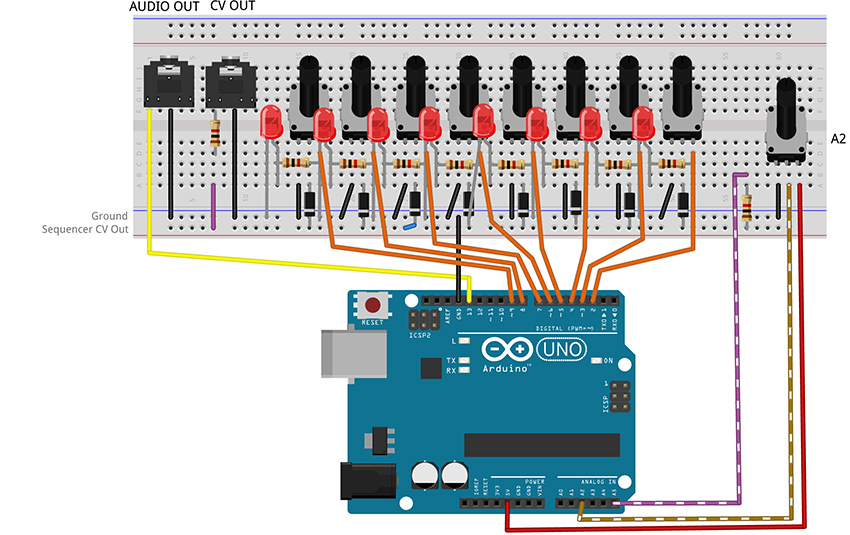
Figure 8 – Fritzing breadboard image of basic step sequencer
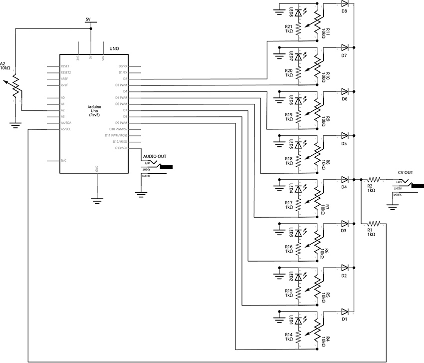
Figure 9 - Fritzing schematic of basic step sequencer
You will need:
- An Arduino Uno.
- A computer running the Arduino IDE software.
- A USB cable that can connect from your computer to the Uno’s USB type-B connector.
- A breadboard.
- Some solid hookup wire or premade wire jumpers.
- 10 1kΩ resistors.
- 9 10kΩ linear potentiometers.
- 8 LEDs (Light Emitting Diodes).
- 8 small signal diodes, such as 1N914.
- An audio amplifier.
- 2 jacks and plugs, to match your amplifier.
- Hand tools.
Connect the Hardware
- Open Fritzing File [link] and navigate to Breadboard view
- Insert all components into breadboard matching image
- Connect all wires on both breadboards
- Connect wires from Arduino to breadboards
- Visually Double-check all connections and wiring
- Connect the Arduino Uno to your Computer
Project Six_A: Basic Step Sequencing Using Delay
PROGRAM THE ARDUINO with the Programmable_Sequencer_A sketch.
- Open the Arduino sketch
- Click the upload button near the top left of the sketch window
								//CODE HEM_Programmable_Sequencer_A*********

								///////////////////

								//This code creates a programmable sequencer that steps through eight different output pins

								//The pins are attached to potentiometers which can be adjusted to provide stepped voltage

								//to the v/oct input of a VCO.

								///////////////////
								//Set up an ARRAY:

								//every time the program sees the word "steps[x]" it will

								//replace it with the "x" number in the list.

								//e.g. from the array below: steps[0] = 9, steps[1] = 8, steps[6] = 3, etc

								int steps[8] = {9, 8, 7, 6, 5, 4, 3, 2};  //the numbers represent the Arduino Digital Pins
								int stepTime = 200; //stepTime will be replaced by the number 200 - change this to change speed

								int stepNum = 0;    //this variable will keep track of which step is turned on.
								//The setup() is the first block of instructions that Arduino runs

								//It happens one time when the hardware is first powered on

								//Your sketch must have one and only one setup

								void setup() {

								  pinMode(steps[0], OUTPUT); //configure pin 9 as an output

								  pinMode(steps[1], OUTPUT); //configure pin 8 as an output

								  pinMode(steps[2], OUTPUT); //configure pin 7 as an output

								  pinMode(steps[3], OUTPUT);

								  pinMode(steps[4], OUTPUT);

								  pinMode(steps[5], OUTPUT);

								  pinMode(steps[6], OUTPUT);

								  pinMode(steps[7], OUTPUT);

								}
								//the  loop runs through each instruction, one at a time until it gets to the end.

								//then it loops back up to the top and does it again

								void loop() {
								  if (stepNum > 7) {

								    stepNum = 0;  //"0" is the first note, "1" is the second, and so on

								  }
								  //this is where the step gets turned on, the code paused, and then the step turned off again

								  digitalWrite(steps[stepNum], HIGH); //toggle selected pin (stepNum[0] = 9) to 5v (step 1 turns on)

								  delay(stepTime);                 //pause code for pre-determined number of milliseconds

								  digitalWrite(steps[stepNum], LOW);  //toggle selected pin to 0v (step 1 turns off)
								  stepNum ++;  //increment stepNum up by one

								}

								//**********END OF CODE
What's Happening?
This code functions in a very similar way to the ToneSEQ sketch in that it uses iteration to count through an array, so that at each new step of the array a new note can be played. (Though this first example will only produce notes if connected to an external voltage-controlled oscillator (VCO) via the CV output jack). One major difference between the ToneSEQ example and the project here is that this array does not include a list of notes, it instead includes a list of digital pins that are each toggled HIGH then LOW in turn. These pins are connected through resistors to LEDs that will light to indicate the current active step. The pins are also connected through potentiometers (knobs) that are manually adjusted so that each step will produce a different voltage (between 0 and about 5 volts). When a step is active, the potentiometer will have 0 volts on one end and 5 volts on the other. The knob can select any voltage in between 0 and 5 volts. When a step is inactive, it will have 0 volts on both ends, so the knob stays at zero volts regardless of its position. Each potentiometer’s wiper (this is the center leg – it acts as a kind of output in our scenario) is tied together (each goes through a diode first so that they will not interfere with each other) and that junction is connected to the CV output jack and the Uno’s own analog input pin #5.
The code starts by making sure that the step number it is going to turn on is within the range of the array:
								  if (stepNum > 7) {

								    stepNum = 0;  //"0" is the first note, "1" is the second, and so on

								  }
Since the code starts with stepNum = 0, this if statement is ignored for now.
The code turns steps on and off in the middle of the loop:
								//this is where the step gets turned on, the code paused, and then the step turned off again

								digitalWrite(steps[stepNum], HIGH); //toggle selected pin (stepNum[0] = 9) to 5v (step 1 turns on)

								delay(stepTime);                 //pause code for pre-determined number of milliseconds

								digitalWrite(steps[stepNum], LOW);  //toggle selected pin to 0v (step 1 turns off)
Each time through the loop, the digitalWrite() function toggles a pin HIGH based on what the stepNum index variable is. When the program starts, stepNum is 0, so steps[0] = 9. This will cause pin 9 to be toggled HIGH. Then the program waits for a certain number of milliseconds as defined by the variable, stepTime (change this at the beginning of the code to try different speeds). Once the delay has ended, the digitalWrite() function is used to toggle the pin LOW again.
Finally, once the pin has been toggled HIGH and toggled LOW again, the variable stepNum gets incremented up by one:
stepNum ++; //increment stepNum up by one
That means that stepNum will equal 1 now. The next time through the loop, steps[1] will address pin 8. Once all 8 pins have been toggled, stepNum++ will set stepNum equal to 8. The next time through the loop, the if statement at the beginning will see that 8 is greater than 7, and reset stepNum to 0 before the next step starts.
You can observe that this code is functioning by watching the pattern of LED lights. To hear anything though, the CV output of this circuit would need to be connected to an external oscillator. The next code example adds an internal oscillator to the project so tones can be produced at the audio output jack. We are going to use the tone() function to play a frequency based on what we read on analog pin 5. For a challenge, try to add this function yourself before moving forward. (Since the next example is just modifying the current code, the additions and deletions have been highlighted to make them easier to locate.)
Project Six_B: Add Internal Oscillator to Basic Sequencer
PROGRAM THE ARDUINO with the Programmable_Sequencer_B sketch.
- Open the Arduino sketch [link]
- Click the upload button near the top left of the sketch window
								//CODE HEM_Programmable_Sequencer_B******

								///////////////////

								//This code adds an internal oscillator to the stepping logic of the previous sketch

								///////////////////
								//Set up an ARRAY:

								//every time the program sees the word "steps[x]" it will

								//replace it with the "x" number in the list.

								//e.g. from the array below: steps[0] = 9, steps[1] = 8, steps[6] = 3, etc

								int steps[8] = {9, 8, 7, 6, 5, 4, 3, 2};  //the numbers represent the Arduino Digital Pins
								int stepTime = 200; //stepTime will be replaced by the number 200 - change this to change speed

								int stepNum = 0;    //this variable will keep track of which step is turned on.
								const int CVPin = A5;     //Analog Input Pin to read CV

								const int tonePin = 13;   //Output pin to produce tone

								int note;
								//The setup() is the first block of instructions that Arduino runs

								//It happens one time when the hardware is first powered on

								//Your sketch must have one and only one setup

								void setup() {

								  pinMode(steps[0], OUTPUT); //configure pin 9 as an output

								  pinMode(steps[1], OUTPUT); //configure pin 8 as an output

								  pinMode(steps[2], OUTPUT); //configure pin 7 as an output

								  pinMode(steps[3], OUTPUT);

								  pinMode(steps[4], OUTPUT);

								  pinMode(steps[5], OUTPUT);

								  pinMode(steps[6], OUTPUT);

								  pinMode(steps[7], OUTPUT);

								}
								//the  loop runs through each instruction, one at a time until it gets to the end.

								//then it loops back up to the top and does it again

								void loop() {
								  if (stepNum > 7) {

								    stepNum = 0;  //"0" is the first note, "1" is the second, and so on

								  }
								  //this is where the step gets turned on, the code paused, and then the step turned off again

								  digitalWrite(steps[stepNum], HIGH); //toggle selected pin (stepNum[0] = 9) to 5v (step 1 turns on)

								  //get value of CV from pin A5

								  //Note: the (void) and the delay are there to deal with ghost voltages

								  //resulting from multiplexing of the ADC and the unbuffered circuitry.

								  //This problem could also be solved with additional circuitry

								  (void)analogRead(CVPin);

								  delay(8);

								  note = map(analogRead(CVPin), 0, 1023, 35, 1200);     //get frequency value by reading the A5 pin

								  tone(tonePin, note);                //write the note to the audio out

								  delay(stepTime);                 //pause code for pre-determined number of milliseconds

								  noTone(tonePin);

								  digitalWrite(steps[stepNum], LOW);  //toggle selected pin to 0v (step 1 turns off)


								  stepNum ++;  //increment stepNum up by one

								}

								//**********END OF CODE
What's Happening?
A new variable, tonePin, was created to represent the pin that our audio output jack will be connected to. This is the pin that the tone() function (described in previous examples) will produce its tone on. Additionally, a variable called note was declared so that we can scale our raw knob reading to a range of notes to provide to the tone() function.
The important new addition to the loop is as follows:
								  //get value of CV from pin A5

								  //Note: the (void) and the delay are there to deal with ghost voltages

								  //resulting from multiplexing of the ADC and the unbuffered circuitry.

								  //This problem could also be solved with additional hardware

								  (void)analogRead(CVPin);

								  delay(8);

								  note = map(analogRead(CVPin), 0, 1023, 35, 1200);     //get frequency value by reading the A5 pin

								  tone(tonePin, note);                //write the note to the audio out

								  delay(stepTime);                 //pause code for pre-determined number of milliseconds

								  noTone(tonePin);

								  digitalWrite(steps[stepNum], LOW);  //toggle selected pin to 0v (step 1 turns off)
This is where we read the voltage of the current step, map it, and apply it to the frequency argument of the tone() function.
There is a little bit of funny business here due to the way the hardware is set up. If the analog pin is read directly it may carry over some voltage from the previous step’s reading. This ghost voltage would cause bad tracking of our steps. As mentioned in the comments, changing the circuit would solve this problem and make the (void)analogRead(CVPin); and delay(8); unnecessary. But every attempt was made to keep the hardware simple and affordable and two lines of code adequately addressed the problem and didn’t cost a penny.
Take note that another consequence of attempting to keep the hardware as minimal as possible is that the audio output and the CV output affect each other. If, while listening to the internal oscillator, you plug the CV into a v/oct input, you will notice a change in pitch of your internal oscillator’s notes. Buffering the voltage from the step knobs using an op amp could solve both the ghost voltage problem and the loading at the analogRead pin when the CV out is connected. This is certainly worth considering for anyone looking to make improvements. However, our current technique is great for quickly generating audio and CV from a relatively simple set of components.
Finally, the delay pauses the program, then noTone() to stops the current note and digitalWrite() toggles the step LOW.
The final addition we will make to this sequencer design is to add knob to control the speed of the stepping. Consider trying it for yourself before uploading the next example. The unused knob is attached to pin A2.
PROJECT SIX_C: Add Speed Control Knob to Basic Sequencer
PROGRAM THE ARDUINO with the Programmable_Sequencer_C sketch.
- Open the Arduino sketch
- Click the upload button near the top left of the sketch window
								//CODE HEM_Programmable_Sequencer_C******

								///////////////////

								//This code adds speed control knob to the stepping logic and in internal

								//oscillator of the previous sketch

								///////////////////
								//Set up an ARRAY:

								//every time the program sees the word "steps[x]" it will

								//replace it with the "x" number in the list.

								//e.g. from the array below: steps[0] = 9, steps[1] = 8, steps[6] = 3, etc

								int steps[8] = {9, 8, 7, 6, 5, 4, 3, 2};  //the numbers represent the Arduino Digital Pins
								int stepTime = 200; //the word stepTime will be replaced by the number 200 - change this to change speed

								int speedKnob = A2; //center pin of Speed knob is attached to pin A0

								int mappedSpeed;    //variable used to store a scaled version of the analog reading of the speed knob

								int stepNum = 0;    //this variable will keep track of which step is turned on.
								int CVPin = A5;     //Analog Input Pin to read CV

								int tonePin = 13;   //Output pin to produce tone

								int note;
								//The setup() is the first block of instructions that Arduino runs

								//It happens one time when the hardware is first powered on

								//Your sketch must have one and only one setup

								void setup() {

								  pinMode(steps[0], OUTPUT); //configure pin 9 as an output

								  pinMode(steps[1], OUTPUT); //configure pin 8 as an output

								  pinMode(steps[2], OUTPUT); //configure pin 7 as an output

								  pinMode(steps[3], OUTPUT);

								  pinMode(steps[4], OUTPUT);

								  pinMode(steps[5], OUTPUT);

								  pinMode(steps[6], OUTPUT);

								  pinMode(steps[7], OUTPUT);

								}
								//the  loop runs through each instruction, one at a time until it gets to the end.

								//then it loops back up to the top and does it again

								void loop() {
								  if (stepNum > 7) {

								    stepNum = 0;  //"0" is the frist note, "1" is the second, and so on

								  }
								  //Read the voltage on knob A0 and store the number (something between 0 and 1023) in the variable "stepTime"

								  stepTime = analogRead(speedKnob); //stepTime and speedKnob are variables declared before the setup()
								  //scale the stepTime variable to a new range that also reverses the direction so the min is higher than the max

								  //0 - 1023 are the min and max of the actual reading, 300 and 1 are the new min and max representing delay times in ms

								  mappedSpeed = map(stepTime, 0, 1023, 300, 1);
								  //this is where the step gets turned on, the code paused, and then the step turned off again

								  digitalWrite(steps[stepNum], HIGH); //toggle selected pin (stepNum[0] = 9) to 5v (step 1 turns on)

								  //get value of CV from pin A5

								  //Note: the (void) and the delay are there to deal with ghost voltages

								  //resulting from multiplexing of the ADC and the unbuffered circuitry.

								  //This problem could also be solved with additonal circuitry

								  (void)analogRead(CVPin);

								  delay(8);

								  note = map(analogRead(CVPin), 0, 1023, 35, 1200);     //get frequency value by reading the A5 pin

								  tone(tonePin, note);                //write the note to the audio out

								  delay(mappedSpeed);                 //pause code for the amount of time set by the knob (milliseconds)

								  digitalWrite(steps[stepNum], LOW);  //toggle selected pin to 0v (step 1 turns off)

								  noTone(tonePin);
								  stepNum ++;  //increment stepNum up by one
								}

								//**********END OF CODE
What's Happening?
The knob attached to A2 is now controlling the speed of the sequencer. The value read on pin A2 is stored in the variable stepTime. This variable is mapped to the new range of 300 to 1 (this range was set by ear and can be adjusted to taste) using the map() function, and then stored in the variable mappedSpeed. This new variable is then used in the delay function that sets the speed of the sequencer.
Conclusion
This 8-step sequencer is a relatively simple design and demonstrates the mechanics of the concept of generating analog outputs by combining digital signals and potentiometers. This example is severely limited by the use of the delay, though. The power of the microcontroller allows for many more features and options that can make our little beep machine into a performable instrument. In the final project of this series, the 8-Step Sequencer will be re-written to run without using a delay for its timing, allowing for a set of new features and enhancements to be explored.
CIRCUIT 5: 8-Step Performance Sequencer
Overview
The hardware for this project just expands what was already connected in the previous circuit by adding 3 additional knobs, 2 buttons, one switch, one additional digital output jack and one digital input jack with a transistor and two resistors to protect the microcontroller pin from unknown voltages.
The example sketches start by redesigning the stepping mechanics of the basic sequencer from the last project to function without using delay. Then, features are added a little bit at a time through a sequence of example sketches with the intention of showing how smaller techniques can be combined into larger, more complex projects. Each new sketch builds on the last and the location of code changes are indicated by the following: “//!!!”. While working through the examples, use the “find” feature in the Arduino IDE to look for the 3 exclamation points. They will show the changes and the nearby comments will explain the techniques.
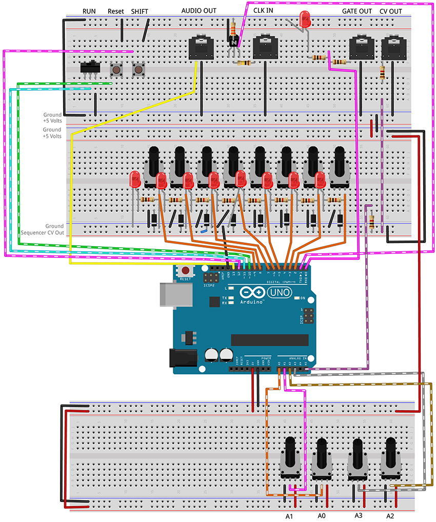
Figure 10 - Fritzing breadboard image of performance sequencer circuit
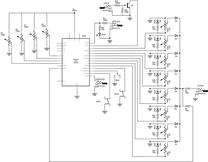
Figure 11 – Fritzing schematic of performance sequencer circuit
You will need:
- An Arduino Uno.
- A computer running the Arduino IDE software.
- A USB cable that can connect from your computer to the Uno’s USB type-B connector.
- Several breadboards.
- Some solid hookup wire or premade wire jumpers.
- 1 x 100kΩ, 1 x 33kΩ, 11 x 1kΩ, and 1 x 100Ω resistors (it is okay to use values that are within about 10 – 15% of these values.
- 12 10kΩ linear potentiometers.
- 9 LEDs (Light Emitting Diodes).
- 8 small signal diodes, such as 1N914.
- 1 toggle switch.
- 2 pushbuttons.
- An audio amplifier.
- 4 jacks and plugs, to match your amplifier and external modules.
- Hand tools.
Open the linked example sketches and look for the “!!!” in the comments:
PROJECT SEVEN_A: Step Sequencer: Controller (no delay)
PROGRAM THE ARDUINO with the A_SEQ_StepController sketch.
- Open the Arduino sketch
- Click the upload button near the top left of the sketch window
								/////////////////////////////////

								//This code shows how to use millis() to keep track of the time that has elapsed since the program started.

								//By comparing the current time to some known time in the past, we can keep a counter running to time our steps.

								//This lets us run a sequencer without using delay() enabling multiple things to happen simultaneously.

								//The sequencer turns on step[] pins in sequence. LEDs light up each step and show the pattern of the steps.

								//These pins also each go through a potentiometer that can set a unique voltage for each of the 8 steps.

								//These potentiometers are tied together through diodes so that steps do not affect each other.

								//The voltage of the current step should be sent to the v/oct input of a VCO to control the frequency of a tone.

								//In the next example, we will tie the output to an Analog Input pin of the Arduino to

								//control the pitch of a built-in tone as well.

								//////////////////////////////////
								//bool (boolean) data type stores a variable that only has two states: true or false

								bool stepStop = false;   //Is it time to STOP the current step?

								bool stepStart = false; //Is it time to START the next step?
								//Set up an ARRAY to represent the step pins of the sequencer:

								//every time the program sees the word "steps[n]" it will

								//replace it with the "n" number in the list.

								//e.g. from the array below: steps[0] = 9, steps[1] = 8, steps[6] = 3, etc

								int steps[8] = {9, 8, 7, 6, 5, 4, 3, 2};  //the numbers represent the Arduino Digital Pins

								int stepNum = 0; //variable to use as index for "steps[ ]"
								void setup() {

								  pinMode(steps[0], OUTPUT); //Configure pin 9 as an output

								  pinMode(steps[1], OUTPUT); //Configure pin 8 as an output

								  pinMode(steps[2], OUTPUT); //Configure pin 7 as an output

								  pinMode(steps[3], OUTPUT); //...

								  pinMode(steps[4], OUTPUT);

								  pinMode(steps[5], OUTPUT);

								  pinMode(steps[6], OUTPUT);

								  pinMode(steps[7], OUTPUT);

								}
								void loop() {

								  //stepController is a custom function that updates the variables startStep and stopStep

								  //the two arguments represent values for: 1. the speed of the steps, 2. the legth of the notes.

								  //knobs are read into the funtion where they are scaled and used to control the sequencer

								  //More details are in the body of the function declaration below (after the loop())

								  stepController(1000, 500);
								  //Check to see if the stepController reports that it is time to STOP the current note

								  if (stepStop == true) {

								    digitalWrite(steps[stepNum], LOW); //turn off the last step

								    stepStop = false; //reset the flag

								  }
								  //Check to see if the stepController reports that it is time to START the new note

								  if (stepStart == true) {

								    stepNum++; //add one to stepNum. "stepNum = stepNum + 1;" would do the same thing. Odd-only counting with stepNum +2;

								    if (stepNum > 7) {

								      stepNum = 0;

								    }

								    digitalWrite(steps[stepNum], HIGH); //turn on the next step

								    stepStart = false; //set our running state to indicate that we are not ready to start a new step

								  }
								}
								//CUSTOM STEPPING FUNCTION

								void stepController(int speedIn, int durIn) {
								  //Variables for Keeping Track of Time (unsigned long will allow us to store very large numbers)

								  static unsigned long previousTime = 0; //keep track of the time we last stepped

								  static unsigned long counter = 0;  //keep track of time since the last step

								  counter = millis() - previousTime;    //counter keeps track of the number of ms since last step began

								  int stepInterval = speedIn;   //speedIn is a variable used to pass numbers into this function from the main loop

								  int stepDuration = durIn;   //this is the gate duration. It should be less than the step interval
								  if (counter > stepDuration) { //check to see if we should STOP the previous step

								    stepStop = true;    //set flag to trigger the stop of the current step

								  }
								  if (counter >= stepInterval && stepStart == false) { //check to see if we should START the next step

								    stepStart = true;   //set flag to trigger the start of the next step

								    previousTime = millis(); //set new previous time to restart counter at beginning of each step

								  }
								  else {

								    stepStart = false;    //make it unambiguous that we should NOT start a new step if the above is not true

								  }

								}
This code uses a custom function to keep track of time. It takes two arguments, one for how long each step should last, and one for how long a note should stay on during each step. The mechanics are very similar to the stepper() function from the Quad Gate Generator example. It uses the millis() function to check the current time against the last time a step was taken. This function is a little bit different in that it sets flags that the rest of the program can check to see if it is time to start a step or if it is time to stop a step. Most of the time we are neither starting a step nor stopping a step.
PROJECT SEVEN_B: Step Sequencer: Internal Oscillator
PROGRAM THE ARDUINO with the B_SEQ_tone sketch.
- Open the Arduino sketch
- Click the upload button near the top left of the sketch window
								/////////////////////////////////

								//This code shows how to use millis() to keep track of the time that has elapsed since the program started.

								//By comparing the current time to some known time in the past, we can keep a counter running to time our steps.

								//This lets us run a sequencer without using delay(). This lets us affect multiple timings without pausing the code.

								//The sequencer turns on step[] pins in sequence. LEDs light up each step and show the pattern of the steps.

								//These pins also each go through a potentiometer that can set a unique voltage for each of the 8 steps.

								//These potentiometers are tied together through diodes so that steps do not affect each other.

								//The voltage of the current step should be sent to the v/oct input of a VCO to control the frequency of a tone.

								//The voltage is also tied to an Analog Input pin of the Arduino to

								//control the frequency of the built-in tone() function as well.

								//

								//Look for "!!!" to find changes

								//////////////////////////////////
								//bool (boolean) data type stores a variable that only has two states: true or false

								bool stepStop = false;   //Is it time to STOP the current step?

								bool stepStart = false; //Is it time to START the next step?
								//Set up an ARRAY to represent the step pins of the sequencer:

								//every time the program sees the word "steps[n]" it will

								//replace it with the "n" number in the list.

								//e.g. from the array below: steps[0] = 9, steps[1] = 8, steps[6] = 3, etc

								int steps[8] = {9, 8, 7, 6, 5, 4, 3, 2};  //the numbers represent the Arduino Digital Pins

								int stepNum = 0; //variable to use as index for "steps[ ]"
								//!!! variables related to the tones

								const int tonePin = 13;   //!!!Output pin to produce tone

								const int CVPin = A5;     //!!!Analog Input Pin to read CV

								int CVVal;      //!!!Variable to store the current level of the CV Input (read on A5)

								int note;           //!!!frequency for the tone() function to play
								void setup() {

								  pinMode(steps[0], OUTPUT); //Configure pin 9 as an output

								  pinMode(steps[1], OUTPUT); //Configure pin 8 as an output

								  pinMode(steps[2], OUTPUT); //Configure pin 7 as an output

								  pinMode(steps[3], OUTPUT);

								  pinMode(steps[4], OUTPUT);

								  pinMode(steps[5], OUTPUT);

								  pinMode(steps[6], OUTPUT);

								  pinMode(steps[7], OUTPUT);

								}
								void loop() {

								  //stepController is a custom function that updates the variables startStep and stopStep

								  //the two arguments represent knobs for: 1. the speed of the steps, 2. the legth of the notes.

								  //knobs are read into the funtion where they are scaled and used to control the sequencer

								  //More details are in the body of the function declaration below (after the loop())

								  stepController(1000, 500);
								  //Check to see if the stepController reports that it is time to STOP the current note

								  if (stepStop == true) {

								    digitalWrite(steps[stepNum], LOW); //turn off the last step

								    //!!!

								    noTone(tonePin);                    //stop tone

								    stepStop = false; //reset the flag

								  }
								  //Check to see if the stepController reports that it is time to START the new note

								  if (stepStart == true) {

								    stepNum++; //add one to stepNum. "stepNum = stepNum + 1;" would do the same thing. Odd-only counting with stepNum +2;

								    if (stepNum > 7) {

								      stepNum = 0;

								    }

								    digitalWrite(steps[stepNum], HIGH); //turn on the next step

								    stepStart = false; //set our running state to indicate that we are not ready to start a new step
								    //!!!get value of CV from pin A5

								    CVVal = analogRead(CVPin);

								    //!!!map function takes the original knob range (0 - 1023) and scales it to the range of the tone function (31 - 4878)

								    note = map(CVVal, 0, 1023, 31, 4878);

								    tone(tonePin, note);  //!!!produce the note to the audio out

								  }
								}
								//CUSTOM STEPPING FUNCTION

								void stepController(int speedIn, int durIn) {
								  //Variables for Keeping Track of Time (unsigned long will allow us to store very large numbers)

								  static unsigned long previousTime = 0; //keep track of the time we last stepped

								  static unsigned long counter = 0;  //keep track of time since the last step

								  counter = millis() - previousTime;    //counter keeps track of the number of ms since last step began

								  int stepInterval = speedIn;   //speedIn is a variable used to pass numbers into this function from the main loop

								  int stepDuration = durIn;   //this is the gate duration. It should be less than the step interval
								  if (counter > stepDuration) { //check to see if we should STOP the previous step

								    stepStop = true;    //set flag to trigger the stop of the current step

								  }
								  if (counter >= stepInterval && stepStart == false) { //check to see if we should START the next step

								    stepStart = true;   //set flag to trigger the start of the next step

								    previousTime = millis(); //set new previous time to restart counter at beginning of each step

								  }
								  else {

								    stepStart = false;    //make it unambiguous that we should NOT start a new step

								  }

								}
The major changes in this example involve the creation of a bunch of variables to handle connecting a reading the CV voltage and some for mapping the raw voltage to a range of frequencies that are useful in the tone() function. Then noTone() is called if the stepStop flag is true. tone() is called if the stepStart flag is true. If neither flag is true, the loop just keeps updating the stepController() function until something changes.
PROJECT SEVEN_C: Step Sequencer: Speed
PROGRAM THE ARDUINO with the C_SEQ_SpeedControl sketch.
- Open the Arduino sketch
- Click the upload button near the top left of the sketch window
								/////////////////////////////////

								//This code shows how to use millis() to keep track of the time that has elapsed since the program started.

								//By comparing the current time to some known time in the past, we can keep a counter running to time our steps.

								//This lets us run a sequencer without using delay(). This lets us affect multiple timings without pausing the code.

								//The sequencer turns on step[] pins in sequence. LEDs light up each step and show the pattern of the steps.

								//These pins also each go through a potentiometer that can set a unique voltage for each of the 8 steps.

								//These potentiometers are tied together through diodes so that steps do not affect each other.

								//The voltage of the current step should be sent to the v/oct input of a VCO to control the frequency of a tone.

								//The voltage is also tied to an Analog Input pin of the Arduino to

								//control the frequency of the built-in tone() function as well.

								//

								//!!! add speed control knob

								//////////////////////////////////
								//Variables for Keeping Track of Time (unsigned long will allow us to store very large numbers)

								unsigned long previousTime = 0; //keep track of the time we last stepped

								unsigned long counter = 0;  //keep track of time since the last step
								//bool (boolean) data type stores a variable that only has two states: true or false

								bool stepStop = false;   //Is it time to STOP the current step?

								bool stepStart = false; //Is it time to START the next step?
								//Set up an ARRAY to represent the step pins of the sequencer:

								//every time the program sees the word "steps[n]" it will

								//replace it with the "n" number in the list.

								//e.g. from the array below: steps[0] = 9, steps[1] = 8, steps[6] = 3, etc

								int steps[8] = {9, 8, 7, 6, 5, 4, 3, 2};  //the numbers represent the Arduino Digital Pins

								int stepNum = 0; //variable to use as index for "steps[ ]"
								//variables related to the tones

								const int tonePin = 13;   //Output pin to produce tone

								const int CVPin = A5;     //Analog Input Pin to read CV

								int CVVal;      //Variable to store the current level of the CV Input (read on A5)

								int note;           //frequency for the tone() function to play
								//!!!Variables for keeping track of stepping speed

								const int speedKnobPin = A2;
								void setup() {

								  pinMode(steps[0], OUTPUT); //Configure pin 9 as an output

								  pinMode(steps[1], OUTPUT); //Configure pin 8 as an output

								  pinMode(steps[2], OUTPUT); //Configure pin 7 as an output

								  pinMode(steps[3], OUTPUT);

								  pinMode(steps[4], OUTPUT);

								  pinMode(steps[5], OUTPUT);

								  pinMode(steps[6], OUTPUT);

								  pinMode(steps[7], OUTPUT);

								}
								void loop() {

								  //stepController is a custom function that updates the variables startStep and stopStep

								  //the two arguments represent knobs for: 1. the speed of the steps, 2. the legth of the notes.

								  //knobs are read into the funtion where they are scaled and used to control the sequencer

								  //More details are in the body of the function declaration below (after the loop())

								  stepController(speedKnobPin, speedKnobPin); //!!!Add knob pin variables to pass changes into function
								  //Check to see if the stepController reports that it is time to STOP the current note

								  if (stepStop == true) {

								    digitalWrite(steps[stepNum], LOW);  //turn off the last step

								    noTone(tonePin);                    //stop tone

								    stepStop = false;                   //reset the flag
								  }
								  //Check to see if the stepController reports that it is time to START the new note

								  if (stepStart == true) {

								    stepNum++; //add one to stepNum. "stepNum = stepNum + 1;" would do the same thing. Odd-only counting with stepNum +2;

								    if (stepNum > 7) {

								      stepNum = 0;

								    }


								    digitalWrite(steps[stepNum], HIGH); //turn on the next step

								    stepStart = false; //set our running state to indicate that we are not ready to start a new step
								    //get value of CV from pin A5

								    //!!!Note: the (void) and the delay are there to deal with ghost voltages

								    //resulting from multiplexing of the ADC and the unbuffered circuitry.

								    //changes to the hardware can make this unnecessary

								    (void)analogRead(CVPin);

								    delay(8);

								    CVVal = analogRead(CVPin);

								    note = map(CVVal, 0, 1000, 31, 4878);

								    tone(tonePin, note);  //write the note to the audio out

								  }
								}
								//CUSTOM STEPPING FUNCTION

								void stepController(int speedIn, int durIn) {
								  //Variables for Keeping Track of Time (unsigned long will allow us to store very large numbers)

								  static unsigned long previousTime = 0; //keep track of the time we last stepped

								  static unsigned long counter = 0;  //keep track of time since the last step

								  counter = millis() - previousTime;    //counter keeps track of the number of ms since last step began

								  int speedValRaw = analogRead(speedIn); //!!! read the speed knob and store the raw value

								  int stepInterval = map(speedValRaw, 0, 1023, 300, 10); //!!! map the value to new speeds (chosen by ear)

								  int durValRaw = analogRead(durIn);  //!!! read the duration knob and store the raw value

								  int stepDuration = map(durValRaw, 0, 1023, 0, stepInterval - 1); //!!! map the duration knob to a new range from very short to an entire step - 1ms
								  if (counter > stepDuration) { //check to see if we should STOP the previous step

								    stepStop = true;    //set flag to trigger the stop of the current step

								  }
								  //!!! Add an if statment to check for the knob to be at Zero. If so, stop the sequencer

								  if (speedValRaw != 0) { //if knob is not set to 0, it sets the speed of the sequencer

								    if (counter >= stepInterval && stepStart == false) { //check to see if we should START the next step

								      stepStart = true;   //set flag to trigger the start of the next step

								      previousTime = millis(); //set new previous time to restart counter at beginning of each step

								    }
								    else {

								      stepStart = false;    //make it unambiguous that we should NOT start a new step

								    }

								  }

								  else { //if knob is at zero, stop sequencer

								    stepStart = false;

								    stepStop = false;

								  }

								}
In this example, the value read from a knob attached to A2 is passed into both arguments of the stepController() function. This will use the same value to control the speed of the stepping and the length of the steps. Experiment with using a second knob for the second argument.
Inside the stepController(), the analog pin is read and then mapped to values that are appropriate for the two parameters.
								  int speedValRaw = analogRead(speedIn); //!!! read the speed knob and store the raw value

								  int stepInterval = map(speedValRaw, 0, 1023, 300, 10); //!!! map the value to new speeds (chosen by

								ear)
Note above, the stepInterval (the speed of stepping) is mapped to my taste. Change the last two numbers in the map function to experiment with different speed control.
								  int durValRaw = analogRead(durIn);  //!!! read the duration knob and store the raw value

								  int stepDuration = map(durValRaw, 0, 1023, 1, stepInterval - 1); //!!! map the duration knob to a new range from very short to an entire step - 1ms
Also note that the durations are automatically scaled based on the step interval and are able to be set from as little as 1 ms to as great as an entire step interval minus one millisecond. This is useful for keeping the start and stop flags unambiguous.
The final thing to mention is that this code stops the sequencer when the knob is all the way down. This is used as a pause function for now. Later this knob position will be where we add a mode to read an external clock signal.
PROJECT SEVEN_D: Step Sequencer: Gate Output
PROGRAM THE ARDUINO with the D_SEQ_GateOutput sketch.
- Open the Arduino sketch
- Click the upload button near the top left of the sketch window
								/////////////////////////////////

								//This code creates an 8-step CV sequencer with and internal oscillator, speed control,

								//and a Gate Output

								//

								//!!! add Gate Output and make steps stay on full duration for CV output

								//turning the Gate Off instead of turning the step off will allow an externally connected

								//Oscillator to function correctly. Otherwise, it will be given two pitches for each step - the

								//pitch selected by the knob when the step is high, and a pitch for zero volts when the step is low

								//////////////////////////////////
								//bool (boolean) data type stores a variable that only has two states: true or false

								bool stepStop = false;   //Is it time to STOP the current step?

								bool stepStart = false; //Is it time to START the next step?
								//Set up an ARRAY to represent the step pins of the sequencer:

								//every time the program sees the word "steps[n]" it will

								//replace it with the "n" number in the list.

								//e.g. from the array below: steps[0] = 9, steps[1] = 8, steps[6] = 3, etc

								int steps[8] = {9, 8, 7, 6, 5, 4, 3, 2};  //the numbers represent the Arduino Digital Pins

								int stepNum = 0; //variable to use as index for "steps[ ]"

								int prevStepNum = 0; //!!!variable to store the previous step number

								//variables related to the tones

								const int tonePin = 13;   //Output pin to produce tone

								const int CVPin = A5;     //Analog Input Pin to read CV

								int CVVal;      //Variable to store the current level of the CV Input (read on A5)

								int note;           //frequency for the tone() function to play
								//Variables for keeping track of stepping speed

								const int speedKnobPin = A2;
								const int gatePin = 0;    //!!!pin to produce a digital gate out
								void setup() {

								  pinMode(steps[0], OUTPUT); //Configure pin 9 as an output

								  pinMode(steps[1], OUTPUT); //Configure pin 8 as an output

								  pinMode(steps[2], OUTPUT); //Configure pin 7 as an output

								  pinMode(steps[3], OUTPUT);

								  pinMode(steps[4], OUTPUT);

								  pinMode(steps[5], OUTPUT);

								  pinMode(steps[6], OUTPUT);

								  pinMode(steps[7], OUTPUT);
								  pinMode(gatePin, OUTPUT);
								}
								void loop() {

								  //stepController is a custom function that steps the variables startStep and stopStep

								  //the two numbers represent 1. the speed of the steps and 2. the length of the notes.

								  //knobs are read into the function where they are scaled and used to control the sequencer

								  //More details are in the body of the function declaration below (after the loop())

								  stepController(speedKnobPin, speedKnobPin);
								  //Check to see if the stepController reports that it is time to STOP the current note

								  if (stepStop == true) {

								    //digitalWrite(steps[stepNum], LOW);  //!!! This moves to right before a new step

								    noTone(tonePin);                    //stop tone

								    digitalWrite(gatePin, LOW);         //!!!toggle GATE LOW instead of turning off step

								    stepStop = false;                   //reset the flag

								  }
								  //Check to see if the stepController reports that it is time to START the new note

								  if (stepStart == true) {

								    stepNum++; //add one to stepNum. "stepNum = stepNum + 1;" would do the same thing. Odd-only counting with stepNum +2;

								    if (stepNum > 7) {

								      stepNum = 0;

								    }

								      digitalWrite(steps[prevStepNum], LOW); //!!!turn off the last step
								      digitalWrite(steps[stepNum], HIGH); //!!!turn on the next step

								      prevStepNum = stepNum;   //!!! save this step so we can turn it off before the next new one.

								      stepStart = false; //set our running state to indicate that we are not ready to start a new step

								    //get value of CV from pin A5

								    //Note: the (void) and the delay are there to deal with ghost voltages

								    //resulting from multiplexing of the ADC and the unbuffered circuitry.

								    //changes to the hardware can make this unnecessary

								    (void)analogRead(CVPin);

								    delay(8);

								    CVVal = analogRead(CVPin);

								    note = map(CVVal, 0, 1000, 31, 4878);

								    tone(tonePin, note);  //write the note to the audio out

								    digitalWrite(gatePin, HIGH);  //!!!turn the gate signal to +5V

								  }
								}
								//CUSTOM STEPPING FUNCTION

								void stepController(int speedIn, int durIn) {
								  //Variables for Keeping Track of Time (unsigned long will allow us to store very large numbers)

								  static unsigned long previousTime = 0; //keep track of the time we last stepped

								  static unsigned long counter = 0;  //keep track of time since the last step

								  counter = millis() - previousTime;    //counter keeps track of the number of ms since last step began

								  int speedValRaw = analogRead(speedIn); //read the speed knob and store the raw value

								  int stepInterval = map(speedValRaw, 0, 1023, 300, 10); //map the value to new speeds (chosen by ear)

								  int durValRaw = analogRead(durIn);  //read the duration knob and store the raw value

								  int stepDuration = map(durValRaw, 0, 1023, 0, stepInterval - 1); //map the duration knob to a new range from very short to an entire step - 1ms
								  if (counter > stepDuration) { //check to see if we should STOP the previous step

								    stepStop = true;    //set flag to trigger the stop of the current step

								  }
								  //Add an if statment to check for the knob to be at Zero. If so, stop the sequencer

								  if (speedValRaw != 0) { //if knob is not set to 0, it sets the speed of the sequencer

								    if (counter >= stepInterval && stepStart == false) { //check to see if we should START the next step

								      stepStart = true;   //set flag to trigger the start of the next step

								      previousTime = millis(); //set new previous time to restart counter at beginning of each step

								    }
								    else {

								      stepStart = false;    //make it unambiguous that we should NOT start a new step

								    }

								  }

								  else { //if knob is at zero, stop sequencer

								    stepStart = false;

								    stepStop = false;

								  }

								}
When connecting the CV to an external oscillator, having the LEDs turn off partway through the step length will cause the oscillator to play two notes for every step: one that you intended, and the other corresponding to zero volts. To fix this, the steps themselves will now be kept high for an entire step length, but a gate signal will be written that corresponds to the step duration control. The internal oscillator will continue to function as before, with notes only playing for the selected note duration. Now the gate output and it’s corresponding LED will mirror this duration, allowing the oscillator to be tuned each step, and the Gate to control the volume through a VCA or other voltage-controlled dynamic module. (Roll your own quick and dirty volume control with the photocell/LED pairing approach described earlier).
PROJECT SEVEN_E: Step Sequencer: Alternate Step Modes
PROGRAM THE ARDUINO with the E_SEQ_SteppingModes sketch.
- Open the Arduino sketch
- Click the upload button near the top left of the sketch window
								/////////////////////////////////

								//This code creates an 8-step CV sequencer with and internal oscillator, speed control,

								//Gate Output, and multiple alternative stepping modes

								//

								//!!! add knob to select stepping modes

								//////////////////////////////////
								//bool (boolean) data type stores a variable that only has two states: true or false

								bool stepStop = false;   //Is it time to STOP the current step?

								bool stepStart = false; //Is it time to START the next step?
								//Set up an ARRAY to represent the step pins of the sequencer:

								//every time the program sees the word "steps[n]" it will

								//replace it with the "n" number in the list.

								//e.g. from the array below: steps[0] = 9, steps[1] = 8, steps[6] = 3, etc

								int steps[8] = {9, 8, 7, 6, 5, 4, 3, 2};  //the numbers represent the Arduino Digital Pins

								int stepNum = 0; //variable to use as index for "steps[ ]"

								int prevStepNum = 0; //variable to store the previous step number

								//variables related to the tones

								const int tonePin = 13;   //Output pin to produce tone

								const int CVPin = A5;     //Analog Input Pin to read CV

								int CVVal;      //Variable to store the current level of the CV Input (read on A5)

								int note;           //frequency for the tone() function to play
								//Variables for keeping track of stepping speed

								const int speedKnobPin = A2;
								//!!!Variables for keeping track of the Mode

								const int modeKnob = A3;  //center pin of Mode Knob is connected to pin A1

								int mode = 0;       //this variable will store the mode
								const int gatePin = 0;    //pin on which to produce a digital gate out
								void setup() {

								  pinMode(steps[0], OUTPUT); //Configure pin 9 as an output

								  pinMode(steps[1], OUTPUT); //Configure pin 8 as an output

								  pinMode(steps[2], OUTPUT); //Configure pin 7 as an output

								  pinMode(steps[3], OUTPUT);

								  pinMode(steps[4], OUTPUT);

								  pinMode(steps[5], OUTPUT);

								  pinMode(steps[6], OUTPUT);

								  pinMode(steps[7], OUTPUT);
								  pinMode(gatePin, OUTPUT);
								}
								void loop() {

								  //stepController is a custom function that steps the variables startStep and stopStep

								  //the two numbers represent 1. the speed of the steps and 2. the legth of the notes.

								  //knobs are read into the funtion where they are scaled and used to control the sequencer

								  //More details are in the body of the function declaration below (after the loop())

								  stepController(speedKnobPin, speedKnobPin);
								  //Check to see if the stepController reports that it is time to STOP the current note

								  if (stepStop == true) {

								    noTone(tonePin);                    //stop tone

								    digitalWrite(gatePin, LOW);         //toggle GATE LOW

								    stepStop = false;                   //reset the flag

								  }
								  //Check to see if the stepController reports that it is time to START the new note

								  if (stepStart == true) {
								    //!!! Use a knob to select from different operating modes.

								    //The map function is used to scale the number of modes down from 1024 to any desired number of modes

								    //These 4 modes (0-3) were chosen based on what seemed most useful and ordered in a sequence that seemed playable

								    mode = map(analogRead(modeKnob), 0, 1023, 0, 4); //read the knob attached to analog pin 1 and map to a range of 0 - 4

								    //!!!A switch structure reads the variable "mode" and does the instructions in whatever case matches the current value of the variable

								    switch (mode) {

								      //Mode 0: HOLD

								      case 0:

								        //do nothing. This will just keep playing the same step.
								        break;
								      //Mode 1: STEP FORWARD

								      case 1:

								        stepNum ++;  //increment stepNum up by one
								        //keep track of which note to play in the 8-note sequence. If we get to the end, start over at 0.

								        if (stepNum > 7) {

								          stepNum = 0;  //"0" is the frist note, "1" is the second, and so on

								        }
								        break;
								      //Mode 2: STEP BACKWARDS

								      case 2:
								        stepNum --; //increment stepNum down by one

								        //keep track of which note to play in the 8-note sequence. If we get to the beginning, start over at 7.

								        if (stepNum < 0) {

								          stepNum = 7;

								        }
								        break;
								      //Mode 3: RANDOM STEPS

								      case 3:

								        //use the random function to randomly pick a step between 0 and 7 each time through the loop

								        stepNum = random(0, 8);
								        break;
								      //Mode 4: STEP FORWARD BY TWOS

								      case 4:

								        stepNum += 2; //increment stepNum up by twos

								        //keep track of which note to play in the 8-note sequence. If we get to the end, start over at 0.

								        if (stepNum > 7) {

								          stepNum = 0;  //"0" is the frist note, "1" is the second, and so on

								        }
								        break;

								    }
								    digitalWrite(steps[prevStepNum], LOW); //turn off the last step
								    digitalWrite(steps[stepNum], HIGH); //turn on the next step

								    prevStepNum = stepNum;  //save this step so we can turn it off before the next new one.

								    stepStart = false; //set our running state to indicate that we are not ready to start a new step
								    //get value of CV from pin A5

								    //Note: the (void) and the delay are there to deal with ghost voltages

								    //resulting from multiplexing of the ADC and the unbuffered circuitry.

								    //changes to the hardware can make this unnecessary

								    (void)analogRead(CVPin);

								    delay(8);

								    CVVal = analogRead(CVPin);

								    note = map(CVVal, 0, 1000, 31, 4878);

								    tone(tonePin, note);  //write the note to the audio out

								    digitalWrite(gatePin, HIGH);  //turn the gate signal to +5V

								  }
								}
								//CUSTOM STEPPING FUNCTION

								void stepController(int speedIn, int durIn) {
								  //Variables for Keeping Track of Time (unsigned long will allow us to store very large numbers)

								  static unsigned long previousTime = 0; //keep track of the time we last stepped

								  static unsigned long counter = 0;  //keep track of time since the last step

								  counter = millis() - previousTime;    //counter keeps track of the number of ms since last step began

								  int speedValRaw = analogRead(speedIn); //read the speed knob and store the raw value

								  int stepInterval = map(speedValRaw, 0, 1023, 300, 10); //map the value to new speeds (chosen by ear)

								  int durValRaw = analogRead(durIn);  //read the duration knob and store the raw value

								  int stepDuration = map(durValRaw, 0, 1023, 0, stepInterval - 1); //map the duration knob to a new range from very short to an entire step - 1ms
								  if (counter > stepDuration) { //check to see if we should STOP the previous step

								    stepStop = true;    //set flag to trigger the stop of the current step

								  }
								  //Add an if statment to check for the knob to be at Zero. If so, stop the sequencer

								  if (speedValRaw != 0) { //if knob is not set to 0, it sets the speed of the sequencer

								    if (counter >= stepInterval && stepStart == false) { //check to see if we should START the next step

								      stepStart = true;   //set flag to trigger the start of the next step

								      previousTime = millis(); //set new previous time to restart counter at beginning of each step

								    }
								    else {

								      stepStart = false;    //make it unambiguous that we should NOT start a new step

								    }

								  }

								  else { //if knob is at zero, stop sequencer

								    stepStart = false;

								    stepStop = false;

								  }
								}
In this example, several new options have been added for how the sequencer moves through its eight possible steps. There are five defined, but any number below 1023 would be possible. The modes are selected by a knob attached to pin A3.
The 5 Modes
Repeat Mode: The sequencer just repeats its current step forever. This can be useful for tuning each step.
Forward Mode: The sequencer advances left to right as normal.
Reverse Mode: The sequencer advances right to left.
Random Mode: The sequencer selects steps randomly at each step interval.
Double Mode: The sequencer advances by two from left to right. It plays every other note.
PROJECT SEVEN_F: Step Sequencer: Run/Pause Switch
PROGRAM THE ARDUINO with the F_SEQ_RunSwitch sketch.
- Open the Arduino sketch
- Click the upload button near the top left of the sketch window
								/////////////////////////////////

								//This code creates an 8-step CV sequencer with and internal oscillator, speed control,

								//Gate Output, multiple alternative stepping modes, and a Run/Pause switch

								//

								//!!! add a switch to run or pause the sequencer

								//////////////////////////////////
								//bool (boolean) data type stores a variable that only has two states: true or false

								bool stepStop = false;   //Is it time to STOP the current step?

								bool stepStart = false; //Is it time to START the next step?
								//Set up an ARRAY to represent the step pins of the sequencer:

								//every time the program sees the word "steps[n]" it will

								//replace it with the "n" number in the list.

								//e.g. from the array below: steps[0] = 9, steps[1] = 8, steps[6] = 3, etc

								int steps[8] = {9, 8, 7, 6, 5, 4, 3, 2};  //the numbers represent the Arduino Digital Pins

								int stepNum = 0; //variable to use as index for "steps[ ]"

								int prevStepNum = 0; //variable to store the previous step number

								//variables related to the tones

								const int tonePin = 13;   //Output pin to produce tone

								const int CVPin = A5;     //Analog Input Pin to read CV

								int CVVal;      //Variable to store the current level of the CV Input (read on A5)

								int note;           //frequency for the tone() function to play
								//Variables for keeping track of stepping speed

								const int speedKnobPin = A2;
								//Variables for keeping track of the Mode

								const int modeKnob = A3;  //center pin of Mode Knob is connected to pin A1

								int mode = 0;       //this variable will store the mode
								const int runsSwitchPin = 11; //!!!Toggle switch to Run the sequencer is connected to this digital input
								const int gatePin = 0;    //pin on which to produce a digital gate out
								void setup() {

								  pinMode(steps[0], OUTPUT); //Configure pin 9 as an output

								  pinMode(steps[1], OUTPUT); //Configure pin 8 as an output

								  pinMode(steps[2], OUTPUT); //Configure pin 7 as an output

								  pinMode(steps[3], OUTPUT);

								  pinMode(steps[4], OUTPUT);

								  pinMode(steps[5], OUTPUT);

								  pinMode(steps[6], OUTPUT);

								  pinMode(steps[7], OUTPUT);
								  //!!!INPUT_PULLUP mode is used for buttons and switches. Pressing the button will cause

								  //the digitalRead() function to return "LOW"

								  pinMode(runsSwitchPin, INPUT_PULLUP); //!!! configure pin as input pullup
								  pinMode(gatePin, OUTPUT);
								}
								void loop() {

								  //!!!Much of the code goes inside a big if statement.

								  //If the sequencer run switch is not "on" move to the "else" statement.

								  if (digitalRead(runsSwitchPin) == LOW) { //!!!if the switch is engaged, run the sequencer
								    //stepController is a custom function that steps the variables startStep and stopStep

								    //the two numbers represent 1. the speed of the steps and 2. the legth of the notes.

								    //knobs are read into the funtion where they are scaled and used to control the sequencer

								    //More details are in the body of the function declaration below (after the loop())

								    stepController(speedKnobPin, speedKnobPin);
								    //Check to see if the stepController reports that it is time to STOP the current note

								    if (stepStop == true) {

								      noTone(tonePin);                    //stop tone

								      digitalWrite(gatePin, LOW);         //toggle GATE LOW

								      stepStop = false;                   //reset the flag

								    }
								    //Check to see if the stepController reports that it is time to START the new note

								    if (stepStart == true) {
								      //Use a knob to select from different operating modes.

								      //The map function is used to scale the number of modes down from 1024 to any desired number of modes

								      //These 4 modes (0-3) were chosen based on what seemed most useful and ordered in a sequence that seemed playable

								      mode = map(analogRead(modeKnob), 0, 1023, 0, 4); //read the knob attached to analog pin 1 and map to a range of 0 - 4

								      //A switch structure reads the variable "mode" and does the instructions in whatever case matches the current value of the variable

								      switch (mode) {

								        //Mode 0: HOLD

								        case 0:

								          //do nothing. This will just keep playing the same step.
								          break;
								        //Mode 1: STEP FORWARD

								        case 1:

								          stepNum ++;  //increment stepNum up by one
								          //keep track of which note to play in the 8-note sequence. If we get to the end, start over at 0.

								          if (stepNum > 7) {

								            stepNum = 0;  //"0" is the frist note, "1" is the second, and so on

								          }
								          break;
								        //Mode 2: STEP BACKWARDS

								        case 2:
								          stepNum --; //increment stepNum down by one

								          //keep track of which note to play in the 8-note sequence. If we get to the beginning, start over at 7.

								          if (stepNum < 0) {

								            stepNum = 7;

								          }
								          break;
								        //Mode 3: RANDOM STEPS

								        case 3:

								          //use the random function to randomly pick a step between 0 and 7 each time through the loop

								          stepNum = random(0, 8);
								          break;
								        //Mode 4: STEP FORWARD BY TWOS

								        case 4:

								          stepNum += 2; //increment stepNum up by twos

								          //keep track of which note to play in the 8-note sequence. If we get to the end, start over at 0.

								          if (stepNum > 7) {

								            stepNum = 0;  //"0" is the frist note, "1" is the second, and so on

								          }
								          break;

								      }
								      digitalWrite(steps[prevStepNum], LOW); //turn off the last step
								      digitalWrite(steps[stepNum], HIGH); //turn on the next step

								      prevStepNum = stepNum;  //save this step so we can turn it off before the next new one.

								      stepStart = false; //set our running state to indicate that we are not ready to start a new step
								      //get value of CV from pin A5

								      //Note: the (void) and the delay are there to deal with ghost voltages

								      //resulting from multiplexing of the ADC and the unbuffered circuitry.

								      //changes to the hardware can make this unnecessary

								      (void)analogRead(CVPin);

								      delay(8);

								      CVVal = analogRead(CVPin);

								      note = map(CVVal, 0, 1000, 31, 4878);

								      tone(tonePin, note);  //write the note to the audio out

								      digitalWrite(gatePin, HIGH);  //turn the gate signal to +5V

								    }

								  }
								  else { //!!! Do this if the Run Switch is not engaged

								    noTone(tonePin);  //turn off any note if run switch disengaged
								  }

								}

								//CUSTOM STEPPING FUNCTION

								void stepController(int speedIn, int durIn) {
								  //Variables for Keeping Track of Time (unsigned long will allow us to store very large numbers)

								  static unsigned long previousTime = 0; //keep track of the time we last stepped

								  static unsigned long counter = 0;  //keep track of time since the last step

								  counter = millis() - previousTime;    //counter keeps track of the number of ms since last step began

								  int speedValRaw = analogRead(speedIn); //read the speed knob and store the raw value

								  int stepInterval = map(speedValRaw, 0, 1023, 300, 10); //map the value to new speeds (chosen by ear)

								  int durValRaw = analogRead(durIn);  //read the duration knob and store the raw value

								  int stepDuration = map(durValRaw, 0, 1023, 0, stepInterval - 1); //map the duration knob to a new range from very short to an entire step - 1ms
								  if (counter > stepDuration) { //check to see if we should STOP the previous step

								    stepStop = true;    //set flag to trigger the stop of the current step

								  }
								  //Add an if statment to check for the knob to be at Zero. If so, stop the sequencer

								  if (speedValRaw != 0) { //if knob is not set to 0, it sets the speed of the sequencer

								    if (counter >= stepInterval && stepStart == false) { //check to see if we should START the next step

								      stepStart = true;   //set flag to trigger the start of the next step

								      previousTime = millis(); //set new previous time to restart counter at beginning of each step

								    }
								    else {

								      stepStart = false;    //make it unambiguous that we should NOT start a new step

								    }

								  }

								  else { //if knob is at zero, stop sequencer

								    stepStart = false;

								    stepStop = false;

								  }

								}
This example adds a switch that must be engaged in order for the sequencer to advance in its current step mode. The switch is set up and read just like a button. An if statement encloses almost all of the loop. If the switch is not engaged, there is no need to do all the stuff in the loop, just turn off the internal oscillator. If the switch is engaged, run the program like normal.
PROJECT SEVEN_G: Step Sequencer: Reset Button
PROGRAM THE ARDUINO with the G_SEQ_ResetButton sketch.
- Open the Arduino sketch
- Click the upload button near the top left of the sketch window
								/////////////////////////////////

								//This code creates an 8-step CV sequencer with and internal oscillator, speed control,

								//Gate Output, multiple alternative stepping modes, a Run/Pause switch, and a Reset Button

								//

								//!!! add a button to reset the current mode to a specific step

								//This button does different things depending on which mode is selected, so there are many new

								//lines of code.

								//////////////////////////////////
								//bool (boolean) data type stores a variable that only has two states: true or false

								bool stepStop = false;   //Is it time to STOP the current step?

								bool stepStart = false; //Is it time to START the next step?
								//Set up an ARRAY to represent the step pins of the sequencer:

								//every time the program sees the word "steps[n]" it will

								//replace it with the "n" number in the list.

								//e.g. from the array below: steps[0] = 9, steps[1] = 8, steps[6] = 3, etc

								int steps[8] = {9, 8, 7, 6, 5, 4, 3, 2};  //the numbers represent the Arduino Digital Pins

								int stepNum = 0; //variable to use as index for "steps[ ]"

								int prevStepNum = 0; //variable to store the previous step number
								//variables related to the tones

								const int tonePin = 13;   //Output pin to produce tone

								const int CVPin = A5;     //Analog Input Pin to read CV

								int CVVal;      //Variable to store the current level of the CV Input (read on A5)

								int note;           //frequency for the tone() function to play
								//Variables for keeping track of stepping speed

								const int speedKnobPin = A2;
								//Variables for keeping track of the Mode

								const int modeKnob = A3;  //center pin of Mode Knob is connected to pin A1

								int mode = 0;       //this variable will store the mode
								const int resetButtonPin = 10; //!!!Pushbutton to reset the sequencer to the first step is connected to this pin

								const int runsSwitchPin = 11; //Toggle switch to Run the sequencer is connected to this digital input
								const int gatePin = 0;    //pin on which to produce a digital gate out
								void setup() {

								  pinMode(steps[0], OUTPUT); //Configure pin 9 as an output

								  pinMode(steps[1], OUTPUT); //Configure pin 8 as an output

								  pinMode(steps[2], OUTPUT); //Configure pin 7 as an output

								  pinMode(steps[3], OUTPUT);

								  pinMode(steps[4], OUTPUT);

								  pinMode(steps[5], OUTPUT);

								  pinMode(steps[6], OUTPUT);

								  pinMode(steps[7], OUTPUT);
								  //INPUT_PULLUP mode is used for buttons and switches. Pressing the button will cause

								  //the digitalRead() function to return "LOW"

								  pinMode(resetButtonPin, INPUT_PULLUP); //!!! configure pin as input pullup for reset button

								  pinMode(runsSwitchPin, INPUT_PULLUP); //configure pin as input pullup
								  pinMode(gatePin, OUTPUT);
								}
								void loop() {

								  //Much of the code goes inside a big if statement.

								  //If the sequencer run switch is not "on" move to the "else" statement.

								  if (digitalRead(runsSwitchPin) == LOW) { //if the switch is engaged, run the sequencer
								    //stepController is a custom function that steps the variables startStep and stopStep

								    //the two numbers represent 1. the speed of the steps and 2. the legth of the notes.

								    //knobs are read into the funtion where they are scaled and used to control the sequencer

								    //More details are in the body of the function declaration below (after the loop())

								    stepController(speedKnobPin, speedKnobPin);
								    //Check to see if the stepController reports that it is time to STOP the current note

								    if (stepStop == true) {

								      noTone(tonePin);                    //stop tone

								      digitalWrite(gatePin, LOW);         //toggle GATE LOW

								      stepStop = false;                   //reset the flag

								    }
								    //Check to see if the stepController reports that it is time to START the new note

								    if (stepStart == true) {
								      //Use a knob to select from different operating modes.

								      //The map function is used to scale the number of modes down from 1024 to any desired number of modes

								      //These 4 modes (0-3) were chosen based on what seemed most useful and ordered in a sequence that seemed playable

								      mode = map(analogRead(modeKnob), 0, 1023, 0, 4); //read the knob attached to analog pin 1 and map to a range of 0 - 4

								      //A switch structure reads the variable "mode" and does the instructions in whatever case matches the current value of the variable

								      switch (mode) {

								        //Mode 0: HOLD

								        case 0:

								          //do nothing. This will just keep playing the same step.

								          //!!!Unless "reset" is pressed, then it steps forward by 1 each step

								          if (digitalRead(resetButtonPin) == LOW) { //!!!read the reset button. if pressed, step forward once each step

								            stepNum++;

								            if (stepNum > 7) {

								              stepNum = 0;

								            }

								          }

								          break;
								        //Mode 1: STEP FORWARD

								        case 1:

								          if (stepNum == -1) { //!!!check to see if reset was pressed while stopped (-1)

								            stepNum = 0; //!!!if reset while stopped, start over at 1st step

								            break;

								          }

								          stepNum ++;  //increment stepNum up by one

								          if (digitalRead(resetButtonPin) == LOW) { //!!!check reset If pressed, step back to 1st step

								            stepNum = 0;

								          }

								          //keep track of which note to play in the 8-note sequence. If we get to the end, start over at 0.

								          if (stepNum > 7) {

								            stepNum = 0;  //"0" is the frist note, "1" is the second, and so on

								          }
								          break;
								        //Mode 2: STEP BACKWARDS

								        case 2:
								          stepNum --; //increment stepNum down by one

								          //keep track of which note to play in the 8-note sequence. If we get to the beginning, start over at 7.

								          if (stepNum < 0) {

								            stepNum = 7;

								          }

								          if (digitalRead(resetButtonPin) == LOW) { //!!!check reset

								            stepNum = 7; //!!!reset to 7 here, since we count backwards in this mode

								          }

								          break;
								        //Mode 3: RANDOM STEPS

								        case 3:

								          if (digitalRead(resetButtonPin) == LOW) { //!!!check reset

								            stepNum = stepNum; //!!!hold the current random point

								          }

								          else {  //!!!if reset is not pressed, do the normal random behavior

								            //use the random function to randomly pick a step between 0 and 7 each time through the loop

								            stepNum = random(0, 8);

								          }

								          break;
								        //Mode 4: STEP FORWARD BY TWOS

								        case 4:

								          stepNum += 2; //increment stepNum up by twos

								          //keep track of which note to play in the 8-note sequence. If we get to the end, start over at 0.

								          if (stepNum > 7) {

								            stepNum = 0;  //"0" is the frist note, "1" is the second, and so on

								          }

								          if (digitalRead(resetButtonPin) == LOW) { //!!!check reset

								            stepNum = 0;

								          }

								          break;

								      }
								      digitalWrite(steps[prevStepNum], LOW); //turn off the last step
								      digitalWrite(steps[stepNum], HIGH); //turn on the next step

								      prevStepNum = stepNum;  //save this step so we can turn it off before the next new one.

								      stepStart = false; //set our running state to indicate that we are not ready to start a new step
								      //get value of CV from pin A5

								      //Note: the (void) and the delay are there to deal with ghost voltages

								      //resulting from multiplexing of the ADC and the unbuffered circuitry.

								      //changes to the hardware can make this unnecessary

								      (void)analogRead(CVPin);

								      delay(8);

								      CVVal = analogRead(CVPin);

								      note = map(CVVal, 0, 1000, 31, 4878);

								      tone(tonePin, note);  //write the note to the audio out

								      digitalWrite(gatePin, HIGH);  //turn the gate signal to +5V

								    }

								  }
								  else { //Do this if the Run Switch is not engaged

								    noTone(tonePin);  //turn off any note if run switch disengaged
								    if (digitalRead(resetButtonPin) == LOW) { //!!!check reset even when not running

								      stepNum = -1; //!!!indicate reset while stopped

								    }

								  }

								}

								//CUSTOM STEPPING FUNCTION

								void stepController(int speedIn, int durIn) {
								  //Variables for Keeping Track of Time (unsigned long will allow us to store very large numbers)

								  static unsigned long previousTime = 0; //keep track of the time we last stepped

								  static unsigned long counter = 0;  //keep track of time since the last step

								  counter = millis() - previousTime;    //counter keeps track of the number of ms since last step began

								  int speedValRaw = analogRead(speedIn); //read the speed knob and store the raw value

								  int stepInterval = map(speedValRaw, 0, 1023, 300, 10); //map the value to new speeds (chosen by ear)

								  int durValRaw = analogRead(durIn);  //read the duration knob and store the raw value

								  int stepDuration = map(durValRaw, 0, 1023, 0, stepInterval - 1); //map the duration knob to a new range from very short to an entire step - 1ms
								  if (counter > stepDuration) { //check to see if we should STOP the previous step

								    stepStop = true;    //set flag to trigger the stop of the current step

								  }
								  //Add an if statment to check for the knob to be at Zero. If so, stop the sequencer

								  if (speedValRaw != 0) { //if knob is not set to 0, it sets the speed of the sequencer

								    if (counter >= stepInterval && stepStart == false) { //check to see if we should START the next step

								      stepStart = true;   //set flag to trigger the start of the next step

								      previousTime = millis(); //set new previous time to restart counter at beginning of each step

								    }
								    else {

								      stepStart = false;    //make it unambiguous that we should NOT start a new step

								    }

								  }

								  else { //if knob is at zero, stop sequencer

								    stepStart = false;

								    stepStop = false;

								  }

								}
The Reset button will have different behaviors in each of the operating modes. This means there are a lot of new lines of code for a relatively simple-seeming addition. The behavior of the Reset button for each mode is as follows:
Mode 1: In step repeat mode, the reset button actually causes the step to advance at each interval. This is a kind of “manual run” button.
Mode 2: In Forward Mode, reset sends the step back to step 1 at the next step start.
Mode 3: In Reverse Mode, it will send the step back to step 8.
Mode 4: In Random Mode, it will hold at the current step until the button is released.
Mode 5: In Double Mode, reset sends the step back to step 1 at the next step start.
PROJECT SEVEN_H: Step Sequencer: Scale Quantizer for Internal Oscillator
PROGRAM THE ARDUINO with the H_SEQ_Quantizer sketch.
- Open the Arduino sketch
- Click the upload button near the top left of the sketch window
								/////////////////////////////////

								//This code creates an 8-step CV sequencer with a quantized internal oscillator, speed control,

								//Gate Output, multiple alternative stepping modes, a Run/Pause switch, and a Reset Button

								//

								//!!! Quantizer function will allow steps to only play notes from within

								//a selected scale. Knobs to select scale type and starting note.

								//////////////////////////////////
								//bool (boolean) data type stores a variable that only has two states: true or false

								bool stepStop = false;   //Is it time to STOP the current step?

								bool stepStart = false; //Is it time to START the next step?
								//Set up an ARRAY to represent the step pins of the sequencer:

								//every time the program sees the word "steps[n]" it will

								//replace it with the "n" number in the list.

								//e.g. from the array below: steps[0] = 9, steps[1] = 8, steps[6] = 3, etc

								int steps[8] = {9, 8, 7, 6, 5, 4, 3, 2};  //the numbers represent the Arduino Digital Pins

								int stepNum = 0; //variable to use as index for "steps[ ]"

								int prevStepNum = 0; //variable to store the previous step number
								//variables related to the tones

								const int tonePin = 13;   //Output pin to produce tone

								const int CVPin = A5;     //Analog Input Pin to read CV

								int CVVal;      //Variable to store the current level of the CV Input (read on A5)

								int note;           //frequency for the tone() function to play
								//Variables for keeping track of stepping speed

								const int speedKnobPin = A2;
								//Variables for keeping track of the Mode

								const int modeKnob = A3;  //center pin of Mode Knob is connected to pin A1

								int mode = 0;       //this variable will store the mode
								//!!!Variables for keeping track of the scale/root/octave

								const int scaleKnob = A1; //!!!Pin connection for scale knob

								const int degreeKnob = A0;  //!!!Pin connection for root knob

								const int resetButtonPin = 10; //Pushbutton to reset the sequencer to the first step is connected to this pin

								const int runsSwitchPin = 11; //Toggle switch to Run the sequencer is connected to this digital input
								const int gatePin = 0;    //pin on which to produce a digital gate out
								void setup() {

								  pinMode(steps[0], OUTPUT); //Configure pin 9 as an output

								  pinMode(steps[1], OUTPUT); //Configure pin 8 as an output

								  pinMode(steps[2], OUTPUT); //Configure pin 7 as an output

								  pinMode(steps[3], OUTPUT);

								  pinMode(steps[4], OUTPUT);

								  pinMode(steps[5], OUTPUT);

								  pinMode(steps[6], OUTPUT);

								  pinMode(steps[7], OUTPUT);
								  //INPUT_PULLUP mode is used for buttons and switches. Pressing the button will cause

								  //the digitalRead() function to return "LOW"

								  pinMode(resetButtonPin, INPUT_PULLUP); //configure pin as input pullup for reset button

								  pinMode(runsSwitchPin, INPUT_PULLUP); //configure pin as input pullup
								  pinMode(gatePin, OUTPUT);
								}
								void loop() {

								  //Much of the code goes inside a big if statement.

								  //If the sequencer run switch is not "on" move to the "else" statement.

								  if (digitalRead(runsSwitchPin) == LOW) { //if the switch is engaged, run the sequencer
								    //stepController is a custom function that steps the variables startStep and stopStep

								    //the two numbers represent 1. the speed of the steps and 2. the legth of the notes.

								    //knobs are read into the funtion where they are scaled and used to control the sequencer

								    //More details are in the body of the function declaration below (after the loop())

								    stepController(speedKnobPin, speedKnobPin);
								    //Check to see if the stepController reports that it is time to STOP the current note

								    if (stepStop == true) {

								      noTone(tonePin);                    //stop tone

								      digitalWrite(gatePin, LOW);         //toggle GATE LOW

								      stepStop = false;                   //reset the flag

								    }
								    //Check to see if the stepController reports that it is time to START the new note

								    if (stepStart == true) {
								      //Use a knob to select from different operating modes.

								      //The map function is used to scale the number of modes down from 1024 to any desired number of modes

								      //These 4 modes (0-3) were chosen based on what seemed most useful and ordered in a sequence that seemed playable

								      mode = map(analogRead(modeKnob), 0, 1023, 0, 4); //read the knob attached to analog pin 1 and map to a range of 0 - 4

								      //A switch structure reads the variable "mode" and does the instructions in whatever case matches the current value of the variable

								      switch (mode) {

								        //Mode 0: HOLD

								        case 0:

								          //do nothing. This will just keep playing the same step.

								          //Unless "reset" is pressed, then it steps forward by 1 each step

								          if (digitalRead(resetButtonPin) == LOW) { //read the reset button. if pressed, step forward once each step

								            stepNum++;

								            if (stepNum > 7) {

								              stepNum = 0;

								            }

								          }

								          break;
								        //Mode 1: STEP FORWARD

								        case 1:

								          if (stepNum == -1) { //check to see if reset was pressed while stopped (-1)

								            stepNum = 0; //if reset while stopped, start over at 1st step

								            break;

								          }

								          stepNum ++;  //increment stepNum up by one

								          if (digitalRead(resetButtonPin) == LOW) { //check reset If pressed, step back to 1st step

								            stepNum = 0;

								          }

								          //keep track of which note to play in the 8-note sequence. If we get to the end, start over at 0.

								          if (stepNum > 7) {

								            stepNum = 0;  //"0" is the frist note, "1" is the second, and so on

								          }
								          break;
								        //Mode 2: STEP BACKWARDS

								        case 2:
								          stepNum --; //increment stepNum down by one

								          //keep track of which note to play in the 8-note sequence. If we get to the beginning, start over at 7.

								          if (stepNum < 0) {

								            stepNum = 7;

								          }

								          if (digitalRead(resetButtonPin) == LOW) { //check reset

								            stepNum = 7; //reset to 7 here, since we count backwards in this mode

								          }

								          break;
								        //Mode 3: RANDOM STEPS

								        case 3:

								          if (digitalRead(resetButtonPin) == LOW) { //check reset

								            stepNum = stepNum; //hold the current random step

								          }

								          else {  //if reset is not pressed, do the normal random behavior

								            //use the random function to randomly pick a step between 0 and 7 each time through the loop

								            stepNum = random(0, 8);

								          }

								          break;
								        //Mode 4: STEP FORWARD BY TWOS

								        case 4:

								          stepNum += 2; //increment stepNum up by twos

								          //keep track of which note to play in the 8-note sequence. If we get to the end, start over at 0.

								          if (stepNum > 7) {

								            stepNum = 0;  //"0" is the frist note, "1" is the second, and so on

								          }

								          if (digitalRead(resetButtonPin) == LOW) { //check reset

								            stepNum = 0;

								          }

								          break;

								      }
								      digitalWrite(steps[prevStepNum], LOW); //turn off the last step
								      digitalWrite(steps[stepNum], HIGH); //turn on the next step

								      prevStepNum = stepNum;  //save this step so we can turn it off before the next new one.

								      stepStart = false; //set our running state to indicate that we are not ready to start a new step
								      //get value of CV from pin A5

								      //Note: the (void) and the delay are there to deal with ghost voltages

								      //resulting from multiplexing of the ADC and the unbuffered circuitry.

								      //changes to the hardware can make this unnecessary

								      (void)analogRead(CVPin);

								      delay(8);

								      CVVal = analogRead(CVPin);
								      //note = map(CVVal, 0, 1000, 31, 4878); //!!!This rough mapping is removed in favor of the quantizer
								      //!!Write the frequency to the tone pin to play through the audio out

								      toneQuantize(CVVal);  //!!!custom function reads the CV input pin, maps the frequency to a scale, and sets the variable "note"
								      tone(tonePin, note);  //!!!plays "note" selected by the toneQuantize function, write the quantized note to the audio out

								      digitalWrite(gatePin, HIGH);  //turn the gate signal to +5V
								    }

								  }
								  else { //Do this if the Run Switch is not engaged

								    noTone(tonePin);  //turn off any note if run switch disengaged
								    if (digitalRead(resetButtonPin) == LOW) { //check reset even when not running

								      stepNum = -1; //indicate reset while stopped

								    }

								  }

								}

								//CUSTOM STEPPING FUNCTION

								void stepController(int speedIn, int durIn) {
								  //Variables for Keeping Track of Time (unsigned long will allow us to store very large numbers)

								  static unsigned long previousTime = 0; //keep track of the time we last stepped

								  static unsigned long counter = 0;  //keep track of time since the last step

								  counter = millis() - previousTime;    //counter keeps track of the number of ms since last step began

								  int speedValRaw = analogRead(speedIn); //read the speed knob and store the raw value

								  int stepInterval = map(speedValRaw, 0, 1023, 300, 10); //map the value to new speeds (chosen by ear)

								  int durValRaw = analogRead(durIn);  //read the duration knob and store the raw value

								  int stepDuration = map(durValRaw, 0, 1023, 0, stepInterval - 1); //map the duration knob to a new range from very short to an entire step - 1ms
								  if (counter > stepDuration) { //check to see if we should STOP the previous step

								    stepStop = true;    //set flag to trigger the stop of the current step

								  }
								  //Add an if statment to check for the knob to be at Zero. If so, stop the sequencer

								  if (speedValRaw != 0) { //if knob is not set to 0, it sets the speed of the sequencer

								    if (counter >= stepInterval && stepStart == false) { //check to see if we should START the next step

								      stepStart = true;   //set flag to trigger the start of the next step

								      previousTime = millis(); //set new previous time to restart counter at beginning of each step

								    }
								    else {

								      stepStart = false;    //make it unambiguous that we should NOT start a new step

								    }

								  }

								  else { //if knob is at zero, stop sequencer

								    stepStart = false;

								    stepStop = false;

								  }
								}
								//!!!NOTE QUANTIZER

								void toneQuantize(int rawVal) {

								  static int  scaleType = 0;

								  //31 = B0, 33 = C1, 35 = Csharp1, 37 = D1, and so on ... 4978 = Dsharp8

								  int chromaticScale[] = {31, 33, 35, 37, 39, 41, 44, 46, 49, 52, 55, 58, 62, 65, 69, 73, 78, 82, 87, 93, 98, 104, 110, 117, 123, 131, 139, 147, 156, 165, 175, 185, 196, 208, 220, 233, 247, 262, 277, 294, 311, 330, 349, 370, 392, 415, 440, 466, 494, 523, 554, 587, 622, 659, 698, 740, 784, 831, 880, 932, 988, 1047, 1109, 1175, 1245, 1319, 1397, 1480, 1568, 1661, 1760, 1865, 1976, 2093, 2217, 2349, 2489, 2637, 2794, 2960, 3136, 3322, 3520, 3729, 3951, 4186, 4435, 4699, 4978};

								  //These masks are used to create a list of notes from the chomatic scale that conform to one octave of other scale types

								  int chromaticMask[14] = {0, 1, 2, 3, 4, 5, 6, 7, 8, 9, 10, 11, 12, 13}; //the sequential numbers here just move through the choromatic scale

								  int majorMask[8] = {0, 2, 4, 5, 7, 9, 11, 12}; //These numbers are used as index values to only read the notes from the chromatic scale that confrom to a major scale

								  int minorMask[8] = {0, 2, 3, 5, 7, 8, 10, 12};

								  int majorPentatonicMask[6] = {0, 2, 4, 7, 9, 12};

								  int minorPentatonicMask[6] = {0, 3, 5, 7, 10, 12};
								  int tonicMask[] = {0, 1, 2, 3, 4, 5, 6, 7, 8, 9, 10, 11}; //add an offset to represent which note to start the scale on

								  int octaveMask[] = {0, 12, 24, 36, 48, 60}; //add an offset to move up by octaves

								  int pitchNum;   //variable to store the index of the note array
								  static int quality;

								  static int octave = 1; //can be made variable by adding a knob

								  static int octaveOffset = 0;  //used for multiple-octave scale modes

								  static int root = 1;  //can be made variable by adding a knob (0 = B, 1 = C, 2 = C#, 3 = D ... 6 = F, etc)

								  int i;  //variable to represent index of array
								  int degree = analogRead(degreeKnob); //store a raw value to set which step of the scale the knob will start on
								  scaleType = analogRead(scaleKnob); //read the scale knob and store the value in "scaleType"
								  int scale = map(scaleType, 0, 1023, 0, 4); //map scale type to select from one of 5 scales
								  switch (scale) {
								    case 0:   //Chromatic

								      //three octaves of a chromatic scale = (12*3) + 2 for a zero for silence and one extra note for a high octave root

								      //i will map the rawVal reading from the variable that is passed to this function, presumably from a

								      //10-bit knob reading

								      i = map(rawVal, 0, 1023, 0, 38); //rawVal gets mapped to index variable "i"

								      i = i + map(degree, 0, 1023, 0, 12);

								      octaveOffset = octave + (i / 12); //divide i by 12, and stores anything left of the decimal + 1 into octaveOffset

								      i = i % 12; //% means divide by 12 and store anything to the right of the decimal as i (this lets us count in base 12)

								      quality = chromaticMask[i]; //choose the scale quality mask

								      pitchNum = octaveMask[octaveOffset] + quality + tonicMask[root]; //pitchNum is our new quantized index value

								      note = chromaticScale[pitchNum]; //pick our note from the the list of frequencies in the 12 tone equal temperment chromatic scale

								      break;
								    case 1:   //Major

								      i = map(rawVal, 0, 1023, 0, 24); //24 gives three octaves of a diatonic scale

								      i = i + map(degree, 0, 1023, 0, 8);

								      octaveOffset = octave + (i / 8); //dividing by 8 here because a major scale only has 8notes to the octave

								      i = i % 8; //modulo 8 here because a major scale has only 8 notes to the octave

								      quality = majorMask[i];

								      pitchNum = octaveMask[octaveOffset] + quality + tonicMask[root];

								      note = chromaticScale[pitchNum];

								      break;
								    case 2:   //Natural Minor

								      i = map(rawVal, 0, 1023, 0, 24);

								      i = i + map(degree, 0, 1023, 0, 8);

								      octaveOffset = octave + (i / 8);

								      i = i % 8;

								      quality = minorMask[i];

								      pitchNum = octaveMask[octaveOffset] + quality + tonicMask[root];

								      note = chromaticScale[pitchNum];

								      break;
								    case 3:   //Major Pentatonic

								      i = map(rawVal, 0, 1023, 0, 16); //16 gives three octaves of a pentatonic scale

								      i = i + map(degree, 0, 1023, 0, 5);

								      octaveOffset = octave + (i / 5); //pentatonic scales have 5 notes to the octave

								      i = i % 5;

								      quality = majorPentatonicMask[i];

								      pitchNum = octaveMask[octaveOffset] + quality + tonicMask[root];

								      note = chromaticScale[pitchNum];

								      break;
								    case 4:   //Minor Pentatonic

								      i = map(rawVal, 0, 1023, 0, 16);

								      i = i + map(degree, 0, 1023, 0, 5);

								      octaveOffset = octave + (i / 5);

								      i = i % 5;

								      quality = minorPentatonicMask[i];

								      pitchNum = octaveMask[octaveOffset] + quality + tonicMask[root];

								      note = chromaticScale[pitchNum];

								      break;
								    default: //if no match, play unquantized notes (currently unused - change scale mapping to output 0 - 5 to use)

								      i = map(rawVal, 0, 1023, 31, 2878);

								      note = i;

								      break;

								  }

								}
The quantizer is defined as a custom function and nearly all of the changes to the sequencer happen in this function definition. The logic of the quantizer is very similar to that used in the earlier quantizer example, but it has been altered here a little bit to better fit the context of a step sequencer. Recall that a quantizer takes some incoming value and constrains its outputs some desired range. This quantizer reads the voltage on the CV pin and causes the internal oscillator to only output notes in a desired scale. The scale can be chosen using a knob attached to pin A1. A knob attached to A0 will cause the tones that are played to shift up in the scale by a selected degree. This will allow all the knobs still play tones in the same scale, but they can be modulated up and down. See the earlier Note Quantizer project for a more detailed explanation of how the quantizer functions.
Note, this only affects the internal oscillator. The CV output voltages are set directly by the knobs and are not processed by the microcontroller and so they cannot be quantized in this way.
PROJECT SEVEN_I: Step Sequencer: Silence Steps
PROGRAM THE ARDUINO with the I_SEQ_SilenceSteps sketch.
- Open the Arduino sketch
- Click the upload button near the top left of the sketch window
								/////////////////////////////////

								//This code creates an 8-step CV sequencer with a Quantized Internal Oscillator, Speed Control,

								//Gate Output, multiple Alternative Stepping Modes, a Run/Pause Switch, and a Reset Button

								//

								//!!! silence steps with knobs at zero

								//////////////////////////////////
								//bool (boolean) data type stores a variable that only has two states: true or false

								bool stepStop = false;   //Is it time to STOP the current step?

								bool stepStart = false; //Is it time to START the next step?
								//Set up an ARRAY to represent the step pins of the sequencer:

								//every time the program sees the word "steps[n]" it will

								//replace it with the "n" number in the list.

								//e.g. from the array below: steps[0] = 9, steps[1] = 8, steps[6] = 3, etc

								int steps[8] = {9, 8, 7, 6, 5, 4, 3, 2};  //the numbers represent the Arduino Digital Pins

								int stepNum = 0; //variable to use as index for "steps[ ]"

								int prevStepNum = 0; //variable to store the previous step number
								//variables related to the tones

								const int tonePin = 13;   //Output pin to produce tone

								const int CVPin = A5;     //Analog Input Pin to read CV

								int CVVal;      //Variable to store the current level of the CV Input (read on A5)

								int note;           //frequency for the tone() function to play
								//Variables for keeping track of stepping speed

								const int speedKnobPin = A2;
								//Variables for keeping track of the Mode

								const int modeKnob = A3;  //center pin of Mode Knob is connected to pin A1

								int mode = 0;       //this variable will store the mode
								//Variables for keeping track of the scale/root/octave

								const int scaleKnob = A1; //Pin connection for scale knob

								const int degreeKnob = A0;  //Pin connection for root knob

								const int resetButtonPin = 10; //Pushbutton to reset the sequencer to the first step is connected to this pin

								const int runsSwitchPin = 11; //Toggle switch to Run the sequencer is connected to this digital input
								const int gatePin = 0;    //pin on which to produce a digital gate out
								void setup() {

								  pinMode(steps[0], OUTPUT); //Configure pin 9 as an output

								  pinMode(steps[1], OUTPUT); //Configure pin 8 as an output

								  pinMode(steps[2], OUTPUT); //Configure pin 7 as an output

								  pinMode(steps[3], OUTPUT);

								  pinMode(steps[4], OUTPUT);

								  pinMode(steps[5], OUTPUT);

								  pinMode(steps[6], OUTPUT);

								  pinMode(steps[7], OUTPUT);
								  //INPUT_PULLUP mode is used for buttons and switches. Pressing the button will cause

								  //the digitalRead() function to return "LOW"

								  pinMode(resetButtonPin, INPUT_PULLUP); //configure pin as input pullup for reset button

								  pinMode(runsSwitchPin, INPUT_PULLUP); //configure pin as input pullup
								  pinMode(gatePin, OUTPUT);
								}
								void loop() {

								  //Much of the code goes inside a big if statement.

								  //If the sequencer run switch is not "on" move to the "else" statement.

								  if (digitalRead(runsSwitchPin) == LOW) { //if the switch is engaged, run the sequencer
								    //stepController is a custom function that steps the variables startStep and stopStep

								    //the two numbers represent 1. the speed of the steps and 2. the legth of the notes.

								    //knobs are read into the funtion where they are scaled and used to control the sequencer

								    //More details are in the body of the function declaration below (after the loop())

								    stepController(speedKnobPin, speedKnobPin);
								    //Check to see if the stepController reports that it is time to STOP the current note

								    if (stepStop == true) {

								      noTone(tonePin);                    //stop tone

								      digitalWrite(gatePin, LOW);         //toggle GATE LOW

								      stepStop = false;                   //reset the flag

								    }
								    //Check to see if the stepController reports that it is time to START the new note

								    if (stepStart == true) {
								      //Use a knob to select from different operating modes.

								      //The map function is used to scale the number of modes down from 1024 to any desired number of modes

								      //These 4 modes (0-3) were chosen based on what seemed most useful and ordered in a sequence that seemed playable

								      mode = map(analogRead(modeKnob), 0, 1023, 0, 4); //read the knob attached to analog pin 1 and map to a range of 0 - 4

								      //A switch structure reads the variable "mode" and does the instructions in whatever case matches the current value of the variable

								      switch (mode) {

								        //Mode 0: HOLD

								        case 0:

								          //do nothing. This will just keep playing the same step.

								          //Unless "reset" is pressed, then it steps forward by 1 each step

								          if (digitalRead(resetButtonPin) == LOW) { //read the reset button. if pressed, step forward once each step

								            stepNum++;

								            if (stepNum > 7) {

								              stepNum = 0;

								            }

								          }

								          break;
								        //Mode 1: STEP FORWARD

								        case 1:

								          if (stepNum == -1) { //check to see if reset was pressed while stopped (-1)

								            stepNum = 0; //if reset while stopped, start over at 1st step

								            break;

								          }

								          stepNum ++;  //increment stepNum up by one

								          if (digitalRead(resetButtonPin) == LOW) { //check reset If pressed, step back to 1st step

								            stepNum = 0;

								          }

								          //keep track of which note to play in the 8-note sequence. If we get to the end, start over at 0.

								          if (stepNum > 7) {

								            stepNum = 0;  //"0" is the frist note, "1" is the second, and so on

								          }
								          break;
								        //Mode 2: STEP BACKWARDS

								        case 2:
								          stepNum --; //increment stepNum down by one

								          //keep track of which note to play in the 8-note sequence. If we get to the beginning, start over at 7.

								          if (stepNum < 0) {

								            stepNum = 7;

								          }

								          if (digitalRead(resetButtonPin) == LOW) { //check reset

								            stepNum = 7; //reset to 7 here, since we count backwards in this mode

								          }

								          break;
								        //Mode 3: RANDOM STEPS

								        case 3:

								          if (digitalRead(resetButtonPin) == LOW) { //check reset

								            stepNum = stepNum; //hold the current random step

								          }

								          else {  //if reset is not pressed, do the normal random behavior

								            //use the random function to randomly pick a step between 0 and 7 each time through the loop

								            stepNum = random(0, 8);

								          }

								          break;
								        //Mode 4: STEP FORWARD BY TWOS

								        case 4:

								          stepNum += 2; //increment stepNum up by twos

								          //keep track of which note to play in the 8-note sequence. If we get to the end, start over at 0.

								          if (stepNum > 7) {

								            stepNum = 0;  //"0" is the frist note, "1" is the second, and so on

								          }

								          if (digitalRead(resetButtonPin) == LOW) { //check reset

								            stepNum = 0;

								          }

								          break;

								      }
								      digitalWrite(steps[prevStepNum], LOW); //turn off the last step
								      digitalWrite(steps[stepNum], HIGH); //turn on the next step

								      prevStepNum = stepNum;  //save this step so we can turn it off before the next new one.

								      stepStart = false; //set our running state to indicate that we are not ready to start a new step
								      //get value of CV from pin A5

								      //Note: the (void) and the delay are there to deal with ghost voltages

								      //resulting from multiplexing of the ADC and the unbuffered circuitry.

								      //changes to the hardware can make this unnecessary

								      (void)analogRead(CVPin);

								      delay(8);

								      CVVal = analogRead(CVPin);
								      //Write the frequency to the tone pin to play through the audio out

								      toneQuantize(CVVal);  //custom function reads the CV input pin, maps the frequency to a scale, and sets the varible "note"

								      if (CVVal == 0) { //!!!when the knob is all the way down, turn off the audio and gate output

								        noTone(tonePin);

								        digitalWrite(gatePin, LOW);

								      }
								      else { //!!!when the knob is in any position other than zero, play the quantized note

								        tone(tonePin, note);  //for all other notes, write the quantized note to the audio out

								        digitalWrite(gatePin, HIGH);  //turn the gate signal to +5V

								      }

								    }

								  }
								  else { //Do this if the Run Switch is not engaged

								    noTone(tonePin);  //turn off any note if run switch disengaged
								    if (digitalRead(resetButtonPin) == LOW) { //check reset even when not running

								      stepNum = -1; //indicate reset while stopped

								    }

								  }

								}

								//CUSTOM STEPPING FUNCTION

								void stepController(int speedIn, int durIn) {
								  //Variables for Keeping Track of Time (unsigned long will allow us to store very large numbers)

								  static unsigned long previousTime = 0; //keep track of the time we last stepped

								  static unsigned long counter = 0;  //keep track of time since the last step

								  counter = millis() - previousTime;    //counter keeps track of the number of ms since last step began

								  int speedValRaw = analogRead(speedIn); //read the speed knob and store the raw value

								  int stepInterval = map(speedValRaw, 0, 1023, 300, 10); //map the value to new speeds (chosen by ear)

								  int durValRaw = analogRead(durIn);  //read the duration knob and store the raw value

								  int stepDuration = map(durValRaw, 0, 1023, 0, stepInterval - 1); //map the duration knob to a new range from very short to an entire step - 1ms
								  if (counter > stepDuration) { //check to see if we should STOP the previous step

								    stepStop = true;    //set flag to trigger the stop of the current step

								  }
								  //Add an if statment to check for the knob to be at Zero. If so, stop the sequencer

								  if (speedValRaw != 0) { //if knob is not set to 0, it sets the speed of the sequencer

								    if (counter >= stepInterval && stepStart == false) { //check to see if we should START the next step

								      stepStart = true;   //set flag to trigger the start of the next step

								      previousTime = millis(); //set new previous time to restart counter at beginning of each step

								    }
								    else {

								      stepStart = false;    //make it unambiguous that we should NOT start a new step

								    }

								  }

								  else { //if knob is at zero, stop sequencer

								    stepStart = false;

								    stepStop = false;

								  }
								}
								//NOTE QUANTIZER

								void toneQuantize(int rawVal) {

								  static int  scaleType = 0;

								  //31 = B0, 33 = C1, 35 = Csharp1, 37 = D1, and so on ... 4978 = Dsharp8

								  int chromaticScale[] = {31, 33, 35, 37, 39, 41, 44, 46, 49, 52, 55, 58, 62, 65, 69, 73, 78, 82, 87, 93, 98, 104, 110, 117, 123, 131, 139, 147, 156, 165, 175, 185, 196, 208, 220, 233, 247, 262, 277, 294, 311, 330, 349, 370, 392, 415, 440, 466, 494, 523, 554, 587, 622, 659, 698, 740, 784, 831, 880, 932, 988, 1047, 1109, 1175, 1245, 1319, 1397, 1480, 1568, 1661, 1760, 1865, 1976, 2093, 2217, 2349, 2489, 2637, 2794, 2960, 3136, 3322, 3520, 3729, 3951, 4186, 4435, 4699, 4978};

								  //These masks are used to create a list of notes from the chomatic scale that conform to one octave of other scale types

								  int chromaticMask[14] = {0, 1, 2, 3, 4, 5, 6, 7, 8, 9, 10, 11, 12, 13}; //the sequential numbers here just move through the choromatic scale

								  int majorMask[8] = {0, 2, 4, 5, 7, 9, 11, 12}; //These numbers are used as index values to only read the notes from the chromatic scale that confrom to a major scale

								  int minorMask[8] = {0, 2, 3, 5, 7, 8, 10, 12};

								  int majorPentatonicMask[6] = {0, 2, 4, 7, 9, 12};

								  int minorPentatonicMask[6] = {0, 3, 5, 7, 10, 12};
								  int tonicMask[] = {0, 1, 2, 3, 4, 5, 6, 7, 8, 9, 10, 11}; //add an offset to represent which note to start the scale on

								  int octaveMask[] = {0, 12, 24, 36, 48, 60}; //add an offset to move up by octaves

								  int pitchNum;   //variable to store the index of the note array
								  static int quality;

								  static int octave = 1; //can be made variable by adding a knob

								  static int octaveOffset = 0;  //used for multiple-octave scale modes

								  static int root = 1;  //can be made variable by adding a knob (0 = B, 1 = C, 2 = C#, 3 = D ... 6 = F, etc)

								  int i;  //variable to represent index of array
								  scaleType = analogRead(scaleKnob); //read the scale knob and store the value in "scaleType"
								  int degree = analogRead(degreeKnob); //store a raw value to set which step of the scale the knob will start on
								  int scale = map(scaleType, 0, 1023, 0, 4); //map scale type to select from one of 5 scales
								  switch (scale) {
								    case 0:   //Chromatic

								      //three octaves of a chromatic scale = (12*3) + 2 for a zero for silence and one extra note for a high octave root

								      //i will map the rawVal reading from the variable that is passed to this function, presumably from a

								      //10-bit knob reading

								      i = map(rawVal, 0, 1023, 0, 38); //rawVal gets mapped to index variable "i"

								      i = i + map(degree, 0, 1023, 0, 12);

								      octaveOffset = octave + (i / 12); //divide i by 12, and stores anything left of the decimal + 1 into octaveOffset

								      i = i % 12; //% means divide by 12 and store anything to the right of the decimal as i (this lets us count in base 12)

								      quality = chromaticMask[i]; //choose the scale quality mask

								      pitchNum = octaveMask[octaveOffset] + quality + tonicMask[root]; //pitchNum is our new quantized index value

								      note = chromaticScale[pitchNum]; //pick our note from the the list of frequencies in the 12 tone equal temperment chromatic scale

								      break;
								    case 1:   //Major

								      i = map(rawVal, 0, 1023, 0, 24); //24 gives three octaves of a diatonic scale

								      i = i + map(degree, 0, 1023, 0, 8);

								      octaveOffset = octave + (i / 8); //dividing by 8 here because a major scale only has 8notes to the octave

								      i = i % 8; //modulo 8 here because a major scale has only 8 notes to the octave

								      quality = majorMask[i];

								      pitchNum = octaveMask[octaveOffset] + quality + tonicMask[root];

								      note = chromaticScale[pitchNum];

								      break;
								    case 2:   //Natural Minor

								      i = map(rawVal, 0, 1023, 0, 24);

								      i = i + map(degree, 0, 1023, 0, 8);

								      octaveOffset = octave + (i / 8);

								      i = i % 8;

								      quality = minorMask[i];

								      pitchNum = octaveMask[octaveOffset] + quality + tonicMask[root];

								      note = chromaticScale[pitchNum];

								      break;
								    case 3:   //Major Pentatonic

								      i = map(rawVal, 0, 1023, 0, 16); //16 gives three octaves of a pentatonic scale

								      i = i + map(degree, 0, 1023, 0, 5);

								      octaveOffset = octave + (i / 5); //pentatonic scales have 5 notes to the octave

								      i = i % 5;

								      quality = majorPentatonicMask[i];

								      pitchNum = octaveMask[octaveOffset] + quality + tonicMask[root];

								      note = chromaticScale[pitchNum];

								      break;
								    case 4:   //Minor Pentatonic

								      i = map(rawVal, 0, 1023, 0, 16);

								      i = i + map(degree, 0, 1023, 0, 5);

								      octaveOffset = octave + (i / 5);

								      i = i % 5;

								      quality = minorPentatonicMask[i];

								      pitchNum = octaveMask[octaveOffset] + quality + tonicMask[root];

								      note = chromaticScale[pitchNum];

								      break;
								    default: //if no match, play unquantized notes (currently unused - change scale mapping to output 0 - 5 to use)

								      i = map(rawVal, 0, 1023, 31, 2878);

								      note = i;

								      break;

								  }

								}
This example shows how to add some logic to silence any step with a knob that is turned all the way down. It can be used to introduce rests into patterns of notes. There is just a little bit of conditional logic added toward the end of the loop to make this work.
This will cause the internal oscillator to go quiet. It will not affect the CV output, but it will cause the Gate Output to stay LOW on these steps. If using the gate to control the volume of your VCO through a VCA, this can affectively silence your external tone as well.
PROJECT SEVEN_J: Step Sequencer: Shift Button_Octave Knob
PROGRAM THE ARDUINO with the J_SEQ_ShiftOctave sketch.
- Open the Arduino sketch [link]
- Click the upload button near the top left of the sketch window
								/////////////////////////////////

								//This code creates an 8-step CV sequencer with a Quantized Internal Oscillator, Speed Control,

								//Gate Output, multiple Alternative Stepping Modes, a Run/Pause Switch, and a Reset Button

								//

								//!!! Add a shift button to access octave parameter on the scale knob

								//////////////////////////////////
								//bool (boolean) data type stores a variable that only has two states: true or false

								bool stepStop = false;   //Is it time to STOP the current step?

								bool stepStart = false; //Is it time to START the next step?
								//Set up an ARRAY to represent the step pins of the sequencer:

								//every time the program sees the word "steps[n]" it will

								//replace it with the "n" number in the list.

								//e.g. from the array below: steps[0] = 9, steps[1] = 8, steps[6] = 3, etc

								int steps[8] = {9, 8, 7, 6, 5, 4, 3, 2};  //the numbers represent the Arduino Digital Pins

								int stepNum = 0; //variable to use as index for "steps[ ]"

								int prevStepNum = 0; //variable to store the previous step number
								//variables related to the tones

								const int tonePin = 13;   //Output pin to produce tone

								const int CVPin = A5;     //Analog Input Pin to read CV

								int CVVal;      //Variable to store the current level of the CV Input (read on A5)

								int note;           //frequency for the tone() function to play
								//Variables for keeping track of stepping speed

								const int speedKnobPin = A2;
								//Variables for keeping track of the Mode

								const int modeKnob = A3;  //center pin of Mode Knob is connected to pin A1

								int mode = 0;       //this variable will store the mode
								//Variables for keeping track of the scale/root/octave

								const int scaleKnob = A1; //Pin connection for scale knob

								const int degreeKnob = A0;  //Pin connection for root knob

								const int resetButtonPin = 10; //Pushbutton to reset the sequencer to the first step is connected to this pin

								const int runsSwitchPin = 11; //Toggle switch to Run the sequencer is connected to this digital input

								const int shiftButtonPin = 12; //!!!Pushbutton to access alternative modes of knobs

								bool shift = HIGH;    //!!!flag to keep track of whether or not the button is being pressed
								const int gatePin = 0;    //pin on which to produce a digital gate out
								void setup() {

								  pinMode(steps[0], OUTPUT); //Configure pin 9 as an output

								  pinMode(steps[1], OUTPUT); //Configure pin 8 as an output

								  pinMode(steps[2], OUTPUT); //Configure pin 7 as an output

								  pinMode(steps[3], OUTPUT);

								  pinMode(steps[4], OUTPUT);

								  pinMode(steps[5], OUTPUT);

								  pinMode(steps[6], OUTPUT);

								  pinMode(steps[7], OUTPUT);
								  //INPUT_PULLUP mode is used for buttons and switches. Pressing the button will cause

								  //the digitalRead() function to return "LOW"

								  pinMode(resetButtonPin, INPUT_PULLUP); //configure pin as input pullup for reset button

								  pinMode(runsSwitchPin, INPUT_PULLUP); //configure pin as input pullup

								  pinMode(shiftButtonPin, INPUT_PULLUP); //!!!configure button pin
								  pinMode(gatePin, OUTPUT);
								}
								void loop() {

								  //Much of the code goes inside a big if statement.

								  //If the sequencer run switch is not "on" move to the "else" statement.

								  if (digitalRead(runsSwitchPin) == LOW) { //if the switch is engaged, run the sequencer
								    //stepController is a custom function that steps the variables startStep and stopStep

								    //the two numbers represent 1. the speed of the steps and 2. the legth of the notes.

								    //knobs are read into the funtion where they are scaled and used to control the sequencer

								    //More details are in the body of the function declaration below (after the loop())

								    stepController(speedKnobPin, speedKnobPin);
								    //Check to see if the stepController reports that it is time to STOP the current note

								    if (stepStop == true) {

								      noTone(tonePin);                    //stop tone

								      digitalWrite(gatePin, LOW);         //toggle GATE LOW

								      stepStop = false;                   //reset the flag

								    }
								    //Check to see if the stepController reports that it is time to START the new note

								    if (stepStart == true) {
								      //Use a knob to select from different operating modes.

								      //The map function is used to scale the number of modes down from 1024 to any desired number of modes

								      //These 4 modes (0-3) were chosen based on what seemed most useful and ordered in a sequence that seemed playable

								      mode = map(analogRead(modeKnob), 0, 1023, 0, 4); //read the knob attached to analog pin 1 and map to a range of 0 - 4

								      //A switch structure reads the variable "mode" and does the instructions in whatever case matches the current value of the variable

								      switch (mode) {

								        //Mode 0: HOLD

								        case 0:

								          //do nothing. This will just keep playing the same step.

								          //Unless "reset" is pressed, then it steps forward by 1 each step

								          if (digitalRead(resetButtonPin) == LOW) { //read the reset button. if pressed, step forward once each step

								            stepNum++;

								            if (stepNum > 7) {

								              stepNum = 0;

								            }

								          }

								          break;
								        //Mode 1: STEP FORWARD

								        case 1:

								          if (stepNum == -1) { //check to see if reset was pressed while stopped (-1)

								            stepNum = 0; //if reset while stopped, start over at 1st step

								            break;

								          }

								          stepNum ++;  //increment stepNum up by one

								          if (digitalRead(resetButtonPin) == LOW) { //check reset If pressed, step back to 1st step

								            stepNum = 0;

								          }

								          //keep track of which note to play in the 8-note sequence. If we get to the end, start over at 0.

								          if (stepNum > 7) {

								            stepNum = 0;  //"0" is the frist note, "1" is the second, and so on

								          }
								          break;
								        //Mode 2: STEP BACKWARDS

								        case 2:
								          stepNum --; //increment stepNum down by one

								          //keep track of which note to play in the 8-note sequence. If we get to the beginning, start over at 7.

								          if (stepNum < 0) {

								            stepNum = 7;

								          }

								          if (digitalRead(resetButtonPin) == LOW) { //check reset

								            stepNum = 7; //reset to 7 here, since we count backwards in this mode

								          }

								          break;
								        //Mode 3: RANDOM STEPS

								        case 3:

								          if (digitalRead(resetButtonPin) == LOW) { //check reset

								            stepNum = stepNum; //hold the current random step

								          }

								          else {  //if reset is not pressed, do the normal random behavior

								            //use the random function to randomly pick a step between 0 and 7 each time through the loop

								            stepNum = random(0, 8);

								          }

								          break;
								        //Mode 4: STEP FORWARD BY TWOS

								        case 4:

								          stepNum += 2; //increment stepNum up by twos

								          //keep track of which note to play in the 8-note sequence. If we get to the end, start over at 0.

								          if (stepNum > 7) {

								            stepNum = 0;  //"0" is the frist note, "1" is the second, and so on

								          }

								          if (digitalRead(resetButtonPin) == LOW) { //check reset

								            stepNum = 0;

								          }

								          break;

								      }
								      digitalWrite(steps[prevStepNum], LOW); //turn off the last step
								      digitalWrite(steps[stepNum], HIGH); //turn on the next step

								      prevStepNum = stepNum;  //save this step so we can turn it off before the next new one.

								      stepStart = false; //set our running state to indicate that we are not ready to start a new step
								      //get value of CV from pin A5

								      //Note: the (void) and the delay are there to deal with ghost voltages

								      //resulting from multiplexing of the ADC and the unbuffered circuitry.

								      //changes to the hardware can make this unnecessary

								      (void)analogRead(CVPin);

								      delay(8);

								      CVVal = analogRead(CVPin);
								      //Write the frequency to the tone pin to play through the audio out

								      toneQuantize(CVVal);  //custom function reads the CV input pin, maps the frequency to a scale, and sets the varible "note"

								      if (CVVal == 0) { //when the knob is all the way down, turn off the audio and gate output

								        noTone(tonePin);

								        digitalWrite(gatePin, LOW);

								      }
								      else { //when the knob is in any position other than zero, play the quanitized note

								        tone(tonePin, note);  //for all other notes, write the quantized note to the audio out

								        digitalWrite(gatePin, HIGH);  //turn the gate signal to +5V

								      }

								    }

								  }
								  else { //Do this if the Run Switch is not engaged

								    noTone(tonePin);  //turn off any note if run switch disengaged
								    if (digitalRead(resetButtonPin) == LOW) { //check reset even when not running

								      stepNum = -1; //indicate reset while stopped

								    }

								  }

								}

								//CUSTOM STEPPING FUNCTION

								void stepController(int speedIn, int durIn) {
								  //Variables for Keeping Track of Time (unsigned long will allow us to store very large numbers)

								  static unsigned long previousTime = 0; //keep track of the time we last stepped

								  static unsigned long counter = 0;  //keep track of time since the last step

								  counter = millis() - previousTime;    //counter keeps track of the number of ms since last step began

								  int speedValRaw = analogRead(speedIn); //read the speed knob and store the raw value

								  int stepInterval = map(speedValRaw, 0, 1023, 300, 10); //map the value to new speeds (chosen by ear)

								  int durValRaw = analogRead(durIn);  //read the duration knob and store the raw value

								  int stepDuration = map(durValRaw, 0, 1023, 0, stepInterval - 1); //map the duration knob to a new range from very short to an entire step - 1ms
								  if (counter > stepDuration) { //check to see if we should STOP the previous step

								    stepStop = true;    //set flag to trigger the stop of the current step

								  }
								  //Add an if statment to check for the knob to be at Zero. If so, stop the sequencer

								  if (speedValRaw != 0) { //if knob is not set to 0, it sets the speed of the sequencer

								    if (counter >= stepInterval && stepStart == false) { //check to see if we should START the next step

								      stepStart = true;   //set flag to trigger the start of the next step

								      previousTime = millis(); //set new previous time to restart counter at beginning of each step

								    }
								    else {

								      stepStart = false;    //make it unambiguous that we should NOT start a new step

								    }

								  }

								  else { //if knob is at zero, stop sequencer

								    stepStart = false;

								    stepStop = false;

								  }
								}
								//NOTE QUANTIZER

								void toneQuantize(int rawVal) {

								  static int  scaleType = 0;

								  //31 = B0, 33 = C1, 35 = Csharp1, 37 = D1, and so on ... 4978 = Dsharp8

								  int chromaticScale[] = {31, 33, 35, 37, 39, 41, 44, 46, 49, 52, 55, 58, 62, 65, 69, 73, 78, 82, 87, 93, 98, 104, 110, 117, 123, 131, 139, 147, 156, 165, 175, 185, 196, 208, 220, 233, 247, 262, 277, 294, 311, 330, 349, 370, 392, 415, 440, 466, 494, 523, 554, 587, 622, 659, 698, 740, 784, 831, 880, 932, 988, 1047, 1109, 1175, 1245, 1319, 1397, 1480, 1568, 1661, 1760, 1865, 1976, 2093, 2217, 2349, 2489, 2637, 2794, 2960, 3136, 3322, 3520, 3729, 3951, 4186, 4435, 4699, 4978};

								  //These masks are used to create a list of notes from the chomatic scale that conform to one octave of other scale types

								  int chromaticMask[14] = {0, 1, 2, 3, 4, 5, 6, 7, 8, 9, 10, 11, 12, 13}; //the sequential numbers here just move through the choromatic scale

								  int majorMask[8] = {0, 2, 4, 5, 7, 9, 11, 12}; //These numbers are used as index values to only read the notes from the chromatic scale that confrom to a major scale

								  int minorMask[8] = {0, 2, 3, 5, 7, 8, 10, 12};

								  int majorPentatonicMask[6] = {0, 2, 4, 7, 9, 12};

								  int minorPentatonicMask[6] = {0, 3, 5, 7, 10, 12};
								  int tonicMask[] = {0, 1, 2, 3, 4, 5, 6, 7, 8, 9, 10, 11}; //add an offset to represent which note to start the scale on

								  int octaveMask[] = {0, 12, 24, 36, 48, 60}; //add an offset to move up by octaves

								  int pitchNum;   //variable to store the index of the note array
								  static int quality;

								  static int octave = 1; //can be made variable by adding a knob

								  static int octaveOffset = 0;  //used for multiple-octave scale modes

								  static int root = 1;  //can be made variable by adding a knob (0 = B, 1 = C, 2 = C#, 3 = D ... 6 = F, etc)

								  int i;  //variable to represent index of array
								  //!!!check the shift button, if it is pressed, change the octave with the scale knob

								  shift = digitalRead(shiftButtonPin);

								    if (shift == LOW) {

								    octave = map(analogRead(scaleKnob), 0, 1023, 0, 3);

								  }
								  else{ //!!! if the shift button is not pressed, change the scale type with the scale knob as usual

								      scaleType = analogRead(scaleKnob); //read the scale knob and store the value in "scaleType"

								  }


								  int degree = analogRead(degreeKnob); //store a raw value to set which step of the scale the knob will start on

								  int scale = map(scaleType, 0, 1023, 0, 4); //map scale type to select from one of 5 scales
								  switch (scale) {
								    case 0:   //Chromatic

								      //three octaves of a chromatic scale = (12*3) + 2 for a zero for silence and one extra note for a high octave root

								      //i will map the rawVal reading from the variable that is passed to this function, presumably from a

								      //10-bit knob reading

								      i = map(rawVal, 0, 1023, 0, 38); //rawVal gets mapped to index variable "i"

								      i = i + map(degree, 0, 1023, 0, 12);

								      octaveOffset = octave + (i / 12); //divide i by 12, and stores anything left of the decimal + 1 into octaveOffset

								      i = i % 12; //% means divide by 12 and store anything to the right of the decimal as i (this lets us count in base 12)

								      quality = chromaticMask[i]; //choose the scale quality mask

								      pitchNum = octaveMask[octaveOffset] + quality + tonicMask[root]; //pitchNum is our new quantized index value

								      note = chromaticScale[pitchNum]; //pick our note from the the list of frequencies in the 12 tone equal temperment chromatic scale

								      break;
								    case 1:   //Major

								      i = map(rawVal, 0, 1023, 0, 24); //24 gives three octaves of a diatonic scale

								      i = i + map(degree, 0, 1023, 0, 8);

								      octaveOffset = octave + (i / 8); //dividing by 8 here because a major scale only has 8notes to the octave

								      i = i % 8; //modulo 8 here because a major scale has only 8 notes to the octave

								      quality = majorMask[i];

								      pitchNum = octaveMask[octaveOffset] + quality + tonicMask[root];

								      note = chromaticScale[pitchNum];

								      break;
								    case 2:   //Natural Minor

								      i = map(rawVal, 0, 1023, 0, 24);

								      i = i + map(degree, 0, 1023, 0, 8);

								      octaveOffset = octave + (i / 8);

								      i = i % 8;

								      quality = minorMask[i];

								      pitchNum = octaveMask[octaveOffset] + quality + tonicMask[root];

								      note = chromaticScale[pitchNum];

								      break;
								    case 3:   //Major Pentatonic

								      i = map(rawVal, 0, 1023, 0, 16); //16 gives three octaves of a pentatonic scale

								      i = i + map(degree, 0, 1023, 0, 5);

								      octaveOffset = octave + (i / 5); //pentatonic scales have 5 notes to the octave

								      i = i % 5;

								      quality = majorPentatonicMask[i];

								      pitchNum = octaveMask[octaveOffset] + quality + tonicMask[root];

								      note = chromaticScale[pitchNum];

								      break;
								    case 4:   //Minor Pentatonic

								      i = map(rawVal, 0, 1023, 0, 16);

								      i = i + map(degree, 0, 1023, 0, 5);

								      octaveOffset = octave + (i / 5);

								      i = i % 5;

								      quality = minorPentatonicMask[i];

								      pitchNum = octaveMask[octaveOffset] + quality + tonicMask[root];

								      note = chromaticScale[pitchNum];

								      break;
								    default: //if no match, play unquantized notes (currently unused - change scale mapping to output 0 - 5 to use)

								      i = map(rawVal, 0, 1023, 31, 2878);

								      note = i;

								      break;

								  }

								}
All the knobs in the design are now in use, but there are still many parameters that it would be nice to have real-time control over. While we could use a microcontroller that has more analog inputs, or employ an additional chip called a multiplexor, both of those solutions require additional hardware. Instead we will use the second button, which I’m referring to as the “Shift Button”, to activate alternative, shifted modes for some of the knobs.
These new lines use the scale knob to update two different parameters in the Quantizer function. When the button is pressed, the variable for the octave is updated allowing the base octave of the quantizer to be changed by turning the scale knob. When the button is not pressed, the octave variable will stay at its most recent value and the knob will update the scale type as usual.
PROJECT SEVEN_K: Step Sequencer: Shift Button_Note Duration Knob
PROGRAM THE ARDUINO with the K_SEQ_ShiftDuration sketch.
- Open the Arduino sketch
- Click the upload button near the top left of the sketch window
								/////////////////////////////////

								//This code creates an 8-step CV sequencer with a Quantized Internal Oscillator, Speed Control,

								//Gate Output, multiple Alternative Stepping Modes, a Run/Pause Switch, and a Reset Button

								//

								//!!! Use shift button to access Note Length (duration) parameter on the Mode Knob

								//////////////////////////////////
								//bool (boolean) data type stores a variable that only has two states: true or false

								bool stepStop = false;   //Is it time to STOP the current step?

								bool stepStart = false; //Is it time to START the next step?
								//Set up an ARRAY to represent the step pins of the sequencer:

								//every time the program sees the word "steps[n]" it will

								//replace it with the "n" number in the list.

								//e.g. from the array below: steps[0] = 9, steps[1] = 8, steps[6] = 3, etc

								int steps[8] = {9, 8, 7, 6, 5, 4, 3, 2};  //the numbers represent the Arduino Digital Pins

								int stepNum = 0; //variable to use as index for "steps[ ]"

								int prevStepNum = 0; //variable to store the previous step number
								//variables related to the tones

								const int tonePin = 13;   //Output pin to produce tone

								const int CVPin = A5;     //Analog Input Pin to read CV

								int CVVal;      //Variable to store the current level of the CV Input (read on A5)

								int note;           //frequency for the tone() function to play
								//Variables for keeping track of stepping speed

								const int speedKnobPin = A2;

								const int durKnobPin = A3; //the duration knob pin is the same as the mode knob pin
								//Variables for keeping track of the Mode

								const int modeKnob = A3;  //center pin of Mode Knob is connected to pin A1

								int mode = 0;       //this variable will store the mode
								//Variables for keeping track of the scale/root/octave

								const int scaleKnob = A1; //Pin connection for scale knob

								const int degreeKnob = A0;  //Pin connection for root knob

								const int resetButtonPin = 10; //Pushbutton to reset the sequencer to the first step is connected to this pin

								const int runsSwitchPin = 11; //Toggle switch to Run the sequencer is connected to this digital input

								const int shiftButtonPin = 12; //Pushbutton to acces alternative modes of knobs

								bool shift = HIGH;    //flag to keep track of whether or not the button is being pressed
								const int gatePin = 0;    //pin on which to produce a digital gate out
								void setup() {

								  pinMode(steps[0], OUTPUT); //Configure pin 9 as an output

								  pinMode(steps[1], OUTPUT); //Configure pin 8 as an output

								  pinMode(steps[2], OUTPUT); //Configure pin 7 as an output

								  pinMode(steps[3], OUTPUT);

								  pinMode(steps[4], OUTPUT);

								  pinMode(steps[5], OUTPUT);

								  pinMode(steps[6], OUTPUT);

								  pinMode(steps[7], OUTPUT);
								  //INPUT_PULLUP mode is used for buttons and switches. Pressing the button will cause

								  //the digitalRead() function to return "LOW"

								  pinMode(resetButtonPin, INPUT_PULLUP); //configure pin as input pullup for reset button

								  pinMode(runsSwitchPin, INPUT_PULLUP); //configure pin as input pullup

								  pinMode(shiftButtonPin, INPUT_PULLUP); //configure button pin
								  pinMode(gatePin, OUTPUT);
								}
								void loop() {

								  //Much of the code goes inside a big if statement.

								  //If the sequencer run switch is not "on" move to the "else" statement.

								  if (digitalRead(runsSwitchPin) == LOW) { //if the switch is engaged, run the sequencer
								    //stepController is a custom function that steps the variables startStep and stopStep

								    //the two numbers represent 1. the speed of the steps and 2. the legth of the notes.

								    //knobs are read into the funtion where they are scaled and used to control the sequencer

								    //More details are in the body of the function declaration below (after the loop())

								    stepController(speedKnobPin, durKnobPin); //!!!add the duration knob here
								    //Check to see if the stepController reports that it is time to STOP the current note

								    if (stepStop == true) {

								      noTone(tonePin);                    //stop tone

								      digitalWrite(gatePin, LOW);         //toggle GATE LOW

								      stepStop = false;                   //reset the flag

								    }
								    //Check to see if the stepController reports that it is time to START the new note

								    if (stepStart == true) {

								      if (shift == HIGH) {  //!!!only update mode when shift is not being pressed

								        //Use a knob to select from different operating modes.

								        //The map function is used to scale the number of modes down from 1024 to any desired number of modes

								        //These 4 modes (0-3) were chosen based on what seemed most useful and ordered in a sequence that seemed playable

								        mode = map(analogRead(modeKnob), 0, 1023, 0, 4); //read the knob attached to analog pin 1 and map to a range of 0 - 4

								      }
								      //A switch structure reads the variable "mode" and does the instructions in whatever case matches the current value of the variable

								      switch (mode) {

								        //Mode 0: HOLD

								        case 0:

								          //do nothing. This will just keep playing the same step.

								          //Unless "reset" is pressed, then it steps forward by 1 each step

								          if (digitalRead(resetButtonPin) == LOW) { //read the reset button. if pressed, step forward once each step

								            stepNum++;

								            if (stepNum > 7) {

								              stepNum = 0;

								            }

								          }

								          break;
								        //Mode 1: STEP FORWARD

								        case 1:

								          if (stepNum == -1) { //check to see if reset was pressed while stopped (-1)

								            stepNum = 0; //if reset while stopped, start over at 1st step

								            break;

								          }

								          stepNum ++;  //increment stepNum up by one

								          if (digitalRead(resetButtonPin) == LOW) { //check reset If pressed, step back to 1st step

								            stepNum = 0;

								          }

								          //keep track of which note to play in the 8-note sequence. If we get to the end, start over at 0.

								          if (stepNum > 7) {

								            stepNum = 0;  //"0" is the frist note, "1" is the second, and so on

								          }
								          break;
								        //Mode 2: STEP BACKWARDS

								        case 2:
								          stepNum --; //increment stepNum down by one

								          //keep track of which note to play in the 8-note sequence. If we get to the beginning, start over at 7.

								          if (stepNum < 0) {

								            stepNum = 7;

								          }

								          if (digitalRead(resetButtonPin) == LOW) { //check reset

								            stepNum = 7; //reset to 7 here, since we count backwards in this mode

								          }

								          break;
								        //Mode 3: RANDOM STEPS

								        case 3:

								          if (digitalRead(resetButtonPin) == LOW) { //check reset

								            stepNum = stepNum; //hold the current random step

								          }

								          else {  //if reset is not pressed, do the normal random behavior

								            //use the random function to randomly pick a step between 0 and 7 each time through the loop

								            stepNum = random(0, 8);

								          }

								          break;
								        //Mode 4: STEP FORWARD BY TWOS

								        case 4:

								          stepNum += 2; //increment stepNum up by twos

								          //keep track of which note to play in the 8-note sequence. If we get to the end, start over at 0.

								          if (stepNum > 7) {

								            stepNum = 0;  //"0" is the frist note, "1" is the second, and so on

								          }

								          if (digitalRead(resetButtonPin) == LOW) { //check reset

								            stepNum = 0;

								          }

								          break;

								      }
								      digitalWrite(steps[prevStepNum], LOW); //turn off the last step
								      digitalWrite(steps[stepNum], HIGH); //turn on the next step

								      prevStepNum = stepNum;  //save this step so we can turn it off before the next new one.

								      stepStart = false; //set our running state to indicate that we are not ready to start a new step
								      //get value of CV from pin A5

								      //Note: the (void) and the delay are there to deal with ghost voltages

								      //resulting from multiplexing of the ADC and the unbuffered circuitry.

								      //changes to the hardware can make this unnecessary

								      (void)analogRead(CVPin);

								      delay(8);

								      CVVal = analogRead(CVPin);
								      //Write the frequency to the tone pin to play through the audio out

								      toneQuantize(CVVal);  //custom function reads the CV input pin, maps the frequency to a scale, and sets the varible "note"

								      if (CVVal == 0) { //when the knob is all the way down, turn off the audio and gate output

								        noTone(tonePin);

								        digitalWrite(gatePin, LOW);

								      }
								      else { //when the knob is in any position other than zero, play the quanitized note

								        tone(tonePin, note);  //for all other notes, write the quantized note to the audio out

								        digitalWrite(gatePin, HIGH);  //turn the gate signal to +5V

								      }

								    }

								  }
								  else { //Do this if the Run Switch is not engaged

								    noTone(tonePin);  //turn off any note if run switch disengaged
								    if (digitalRead(resetButtonPin) == LOW) { //check reset even when not running

								      stepNum = -1; //indicate reset while stopped

								    }

								  }

								}

								//CUSTOM STEPPING FUNCTION

								void stepController(int speedIn, int durIn) {
								  //Variables for Keeping Track of Time (unsigned long will allow us to store very large numbers)

								  static unsigned long previousTime = 0; //keep track of the time we last stepped

								  static unsigned long counter = 0;  //keep track of time since the last step

								  counter = millis() - previousTime;    //counter keeps track of the number of ms since last step began

								  int speedValRaw = analogRead(speedIn); //read the speed knob and store the raw value

								  int stepInterval = map(speedValRaw, 0, 1023, 300, 10); //map the value to new speeds (chosen by ear)

								  //!!! these lines move  int durValRaw = analogRead(durIn);  //read the duration knob and store the raw value

								  //!!!these lines move   int stepDuration = map(durValRaw, 0, 1023, 0, stepInterval - 1); //map the duration knob to a new range from very short to an entire step - 1ms

								  static int stepDuration = stepInterval - 1; //this will set the duration if the shift button has not been pressed

								  static int durValRaw = 1023; //initalize value
								  if (shift == LOW) { //!!!check the shift button

								    //!!!read the knob and update the variable only when the shift button is pressed

								    durValRaw = analogRead(durKnobPin);

								  }
								  //!!!Update the length of the note to keep it relative to the speed

								  stepDuration = map(durValRaw, 0, 1023, 0, stepInterval - 1);

								  if (counter > stepDuration) { //check to see if we should STOP the previous step

								    stepStop = true;    //set flag to trigger the stop of the current step

								  }
								  //Add an if statment to check for the knob to be at Zero. If so, stop the sequencer

								  if (speedValRaw != 0) { //if knob is not set to 0, it sets the speed of the sequencer

								    if (counter >= stepInterval && stepStart == false) { //check to see if we should START the next step

								      stepStart = true;   //set flag to trigger the start of the next step

								      previousTime = millis(); //set new previous time to restart counter at beginning of each step

								    }
								    else {

								      stepStart = false;    //make it unambiguous that we should NOT start a new step

								    }

								  }

								  else { //if knob is at zero, stop sequencer

								    stepStart = false;

								    stepStop = false;

								  }
								}
								//NOTE QUANTIZER

								void toneQuantize(int rawVal) {

								  static int  scaleType = 0;

								  //31 = B0, 33 = C1, 35 = Csharp1, 37 = D1, and so on ... 4978 = Dsharp8

								  int chromaticScale[] = {31, 33, 35, 37, 39, 41, 44, 46, 49, 52, 55, 58, 62, 65, 69, 73, 78, 82, 87, 93, 98, 104, 110, 117, 123, 131, 139, 147, 156, 165, 175, 185, 196, 208, 220, 233, 247, 262, 277, 294, 311, 330, 349, 370, 392, 415, 440, 466, 494, 523, 554, 587, 622, 659, 698, 740, 784, 831, 880, 932, 988, 1047, 1109, 1175, 1245, 1319, 1397, 1480, 1568, 1661, 1760, 1865, 1976, 2093, 2217, 2349, 2489, 2637, 2794, 2960, 3136, 3322, 3520, 3729, 3951, 4186, 4435, 4699, 4978};

								  //These masks are used to create a list of notes from the chomatic scale that conform to one octave of other scale types

								  int chromaticMask[14] = {0, 1, 2, 3, 4, 5, 6, 7, 8, 9, 10, 11, 12, 13}; //the sequential numbers here just move through the choromatic scale

								  int majorMask[8] = {0, 2, 4, 5, 7, 9, 11, 12}; //These numbers are used as index values to only read the notes from the chromatic scale that confrom to a major scale

								  int minorMask[8] = {0, 2, 3, 5, 7, 8, 10, 12};

								  int majorPentatonicMask[6] = {0, 2, 4, 7, 9, 12};

								  int minorPentatonicMask[6] = {0, 3, 5, 7, 10, 12};
								  int tonicMask[] = {0, 1, 2, 3, 4, 5, 6, 7, 8, 9, 10, 11}; //add an offset to represent which note to start the scale on

								  int octaveMask[] = {0, 12, 24, 36, 48, 60}; //add an offset to move up by octaves

								  int pitchNum;   //variable to store the index of the note array
								  static int quality;

								  static int octave = 1; //can be made variable by adding a knob

								  static int octaveOffset = 0;  //used for multiple-octave scale modes

								  static int root = 1;  //can be made variable by adding a knob (0 = B, 1 = C, 2 = C#, 3 = D ... 6 = F, etc)

								  int i;  //variable to represent index of array
								  //check the shift button, if it is pressed, change the octave with the scale knob

								  shift = digitalRead(shiftButtonPin);

								  if (shift == LOW) {

								    octave = map(analogRead(scaleKnob), 0, 1023, 0, 3);

								  }
								  else { // if the shift button is not pressed, change the scale type with the scale knob as usual

								    scaleType = analogRead(scaleKnob); //read the scale knob and store the value in "scaleType"

								  }
								  int degree = analogRead(degreeKnob); //store a raw value to set which step of the scale the knob will start on

								  int scale = map(scaleType, 0, 1023, 0, 4); //map scale type to select from one of 5 scales
								  switch (scale) {
								    case 0:   //Chromatic

								      //three octaves of a chromatic scale = (12*3) + 2 for a zero for silence and one extra note for a high octave root

								      //i will map the rawVal reading from the variable that is passed to this function, presumably from a

								      //10-bit knob reading

								      i = map(rawVal, 0, 1023, 0, 38); //rawVal gets mapped to index variable "i"

								      i = i + map(degree, 0, 1023, 0, 12);

								      octaveOffset = octave + (i / 12); //divide i by 12, and stores anything left of the decimal + 1 into octaveOffset

								      i = i % 12; //% means divide by 12 and store anything to the right of the decimal as i (this lets us count in base 12)

								      quality = chromaticMask[i]; //choose the scale quality mask

								      pitchNum = octaveMask[octaveOffset] + quality + tonicMask[root]; //pitchNum is our new quantized index value

								      note = chromaticScale[pitchNum]; //pick our note from the the list of frequencies in the 12 tone equal temperment chromatic scale

								      break;
								    case 1:   //Major

								      i = map(rawVal, 0, 1023, 0, 24); //24 gives three octaves of a diatonic scale

								      i = i + map(degree, 0, 1023, 0, 8);

								      octaveOffset = octave + (i / 8); //dividing by 8 here because a major scale only has 8notes to the octave

								      i = i % 8; //modulo 8 here because a major scale has only 8 notes to the octave

								      quality = majorMask[i];

								      pitchNum = octaveMask[octaveOffset] + quality + tonicMask[root];

								      note = chromaticScale[pitchNum];

								      break;
								    case 2:   //Natural Minor

								      i = map(rawVal, 0, 1023, 0, 24);

								      i = i + map(degree, 0, 1023, 0, 8);

								      octaveOffset = octave + (i / 8);

								      i = i % 8;

								      quality = minorMask[i];

								      pitchNum = octaveMask[octaveOffset] + quality + tonicMask[root];

								      note = chromaticScale[pitchNum];

								      break;
								    case 3:   //Major Pentatonic

								      i = map(rawVal, 0, 1023, 0, 16); //16 gives three octaves of a pentatonic scale

								      i = i + map(degree, 0, 1023, 0, 5);

								      octaveOffset = octave + (i / 5); //pentatonic scales have 5 notes to the octave

								      i = i % 5;

								      quality = majorPentatonicMask[i];

								      pitchNum = octaveMask[octaveOffset] + quality + tonicMask[root];

								      note = chromaticScale[pitchNum];

								      break;
								    case 4:   //Minor Pentatonic

								      i = map(rawVal, 0, 1023, 0, 16);

								      i = i + map(degree, 0, 1023, 0, 5);

								      octaveOffset = octave + (i / 5);

								      i = i % 5;

								      quality = minorPentatonicMask[i];

								      pitchNum = octaveMask[octaveOffset] + quality + tonicMask[root];

								      note = chromaticScale[pitchNum];

								      break;
								    default: //if no match, play unquantized notes (currently unused - change scale mapping to output 0 - 5 to use)

								      i = map(rawVal, 0, 1023, 31, 2878);

								      note = i;

								      break;

								  }

								}
In this update, the shift button is used to activate an alternative mode for the mode selection knob in addition to the alternate mode selection from the previous example. While the button is pressed, the mode selection knob will be used to update a variable controlling the note length. This will allow the mode knob to set the duration of the steps. When the shift button is not being pressed, the mode knob will update the current stepping mode as usual and the note length parameter will stay wherever it was when the shift button was released.
PROJECT SEVEN_L: Step Sequencer: Change Detection for Shifted Values
PROGRAM THE ARDUINO with the L_SEQ_ChangeDetection sketch.
- Open the Arduino sketch
- Click the upload button near the top left of the sketch window
/////////////////////////////////
//This code creates an 8-step CV sequencer with a Quantized Internal Oscillator, Speed Control,
//Gate Output, multiple Alternative Stepping Modes, a Run/Pause Switch, and a Reset Button
//
//!!! Create a change detection function so that knobs that have shift parameters only
//change value when they are moved. This will keep them from updating to a new knob position
//when the shift button is released.
//////////////////////////////////
//bool (boolean) data type stores a variable that only has two states: true or false
bool stepStop = false; //Is it time to STOP the current step?
bool stepStart = false; //Is it time to START the next step?
//Set up an ARRAY to represent the step pins of the sequencer:
//every time the program sees the word "steps[n]" it will
//replace it with the "n" number in the list.
//e.g. from the array below: steps[0] = 9, steps[1] = 8, steps[6] = 3, etc
int steps[8] = {9, 8, 7, 6, 5, 4, 3, 2}; //the numbers represent the Arduino Digital Pins
int stepNum = 0; //variable to use as index for "steps[ ]"
int prevStepNum = 0; //variable to store the previous step number
//variables related to the tones
const int tonePin = 13; //Output pin to produce tone
const int CVPin = A5; //Analog Input Pin to read CV
int CVVal; //Variable to store the current level of the CV Input (read on A5)
int note; //frequency for the tone() function to play
//Variables for keeping track of stepping speed
const int speedKnobPin = A2;
const int durKnobPin = A3; //the duration knob pin is the same as the mode knob pin
//Variables for keeping track of the Mode
const int modeKnob = A3; //center pin of Mode Knob is connected to pin A1
int modeRaw = 0; //!!!variable to store the mode knob reading
int newMode = 1; //!!!this will update the mode when the button is released
int mode = 1; //!!!keep track of the current mode
//Variables for keeping track of the scale/root/octave
const int scaleKnob = A1; //Pin connection for scale knob
const int degreeKnob = A0; //Pin connection for root knob
const int resetButtonPin = 10; //Pushbutton to reset the sequencer to the first step is connected to this pin
const int runsSwitchPin = 11; //Toggle switch to Run the sequencer is connected to this digital input
const int shiftButtonPin = 12; //Pushbutton to acces alternative modes of knobs
bool shift = HIGH; //flag to keep track of whether or not the button is being pressed
const int gatePin = 0; //pin on which to produce a digital gate out
void setup() {
pinMode(steps[0], OUTPUT); //Configure pin 9 as an output
pinMode(steps[1], OUTPUT); //Configure pin 8 as an output
pinMode(steps[2], OUTPUT); //Configure pin 7 as an output
pinMode(steps[3], OUTPUT);
pinMode(steps[4], OUTPUT);
pinMode(steps[5], OUTPUT);
pinMode(steps[6], OUTPUT);
pinMode(steps[7], OUTPUT);
//INPUT_PULLUP mode is used for buttons and switches. Pressing the button will cause
//the digitalRead() function to return "LOW"
pinMode(resetButtonPin, INPUT_PULLUP); //configure pin as input pullup for reset button
pinMode(runsSwitchPin, INPUT_PULLUP); //configure pin as input pullup
pinMode(shiftButtonPin, INPUT_PULLUP); //configure button pin
pinMode(gatePin, OUTPUT);
}
void loop() {
//Much of the code goes inside a big if statement.
//If the sequencer run switch is not "on" move to the "else" statement.
if (digitalRead(runsSwitchPin) == LOW) { //if the switch is engaged, run the sequencer
//stepController is a custom function that steps the variables startStep and stopStep
//the two numbers represent 1. the speed of the steps and 2. the legth of the notes.
//knobs are read into the funtion where they are scaled and used to control the sequencer
//More details are in the body of the function declaration below (after the loop())
stepController(speedKnobPin, durKnobPin); //add the duration knob here
//Check to see if the stepController reports that it is time to STOP the current note
if (stepStop == true) {
noTone(tonePin); //stop tone
digitalWrite(gatePin, LOW); //toggle GATE LOW
stepStop = false; //reset the flag
}
modeRaw = analogRead(modeKnob); //!!!Read Mode Knob
//Check to see if the stepController reports that it is time to START the new note
if (stepStart == true) {
// !!! This gets replaced by the changeRead logic
// if (shift == HIGH) { //only update mode when shift is not being pressed
// //Use a knob to select from different operating modes.
// //The map function is used to scale the number of modes down from 1024 to any desired number of modes
// //These 4 modes (0-3) were chosen based on what seemed most useful and ordered in a sequence that seemed playable
// mode = map(analogRead(modeKnob), 0, 1023, 0, 4); //read the knob attached to analog pin 1 and map to a range of 0 - 4
// }
if (changeRead(shiftButtonPin, modeKnob) == 2) { //!!!pass the shift pin and knob pin to changeRead
//if the knob has started moving since the shift button was released, update the mode
//use a knob to select from different operating modes.
//the map function is used to scale the number of modes down from 1024 to any desired number of modes
//These 4 modes (0-3) were chosen based on what seemed most useful and ordered in a sequence that seemed playable
newMode = map(modeRaw, 0, 1023, 0, 4); //read the knob attached to analog pin 1 and map to a range of 0 - 4
}
mode = newMode; //!!!update the mode if the knob has been intentionally changed, otherwise newMode will not have changed
//A switch structure reads the variable "mode" and does the instructions in whatever case matches the current value of the variable
switch (mode) {
//Mode 0: HOLD
case 0:
//do nothing. This will just keep playing the same step.
//Unless "reset" is pressed, then it steps forward by 1 each step
if (digitalRead(resetButtonPin) == LOW) { //read the reset button. if pressed, step forward once each step
stepNum++;
if (stepNum > 7) {
stepNum = 0;
}
}
break;
//Mode 1: STEP FORWARD
case 1:
if (stepNum == -1) { //check to see if reset was pressed while stopped (-1)
stepNum = 0; //if reset while stopped, start over at 1st step
break;
}
stepNum ++; //increment stepNum up by one
if (digitalRead(resetButtonPin) == LOW) { //check reset If pressed, step back to 1st step
stepNum = 0;
}
//keep track of which note to play in the 8-note sequence. If we get to the end, start over at 0.
if (stepNum > 7) {
stepNum = 0; //"0" is the frist note, "1" is the second, and so on
}
break;
//Mode 2: STEP BACKWARDS
case 2:
stepNum --; //increment stepNum down by one
//keep track of which note to play in the 8-note sequence. If we get to the beginning, start over at 7.
if (stepNum < 0) {
stepNum = 7;
}
if (digitalRead(resetButtonPin) == LOW) { //check reset
stepNum = 7; //reset to 7 here, since we count backwards in this mode
}
break;
//Mode 3: RANDOM STEPS
case 3:
if (digitalRead(resetButtonPin) == LOW) { //check reset
stepNum = stepNum; //hold the current random step
}
else { //if reset is not pressed, do the normal random behavior
//use the random function to randomly pick a step between 0 and 7 each time through the loop
stepNum = random(0, 8);
}
break;
//Mode 4: STEP FORWARD BY TWOS
case 4:
stepNum += 2; //increment stepNum up by twos
//keep track of which note to play in the 8-note sequence. If we get to the end, start over at 0.
if (stepNum > 7) {
stepNum = 0; //"0" is the frist note, "1" is the second, and so on
}
if (digitalRead(resetButtonPin) == LOW) { //check reset
stepNum = 0;
}
break;
}
digitalWrite(steps[prevStepNum], LOW); //turn off the last step
digitalWrite(steps[stepNum], HIGH); //turn on the next step
prevStepNum = stepNum; //save this step so we can turn it off before the next new one.
stepStart = false; //set our running state to indicate that we are not ready to start a new step
//get value of CV from pin A5
//Note: the (void) and the delay are there to deal with ghost voltages
//resulting from multiplexing of the ADC and the unbuffered circuitry.
//changes to the hardware can make this unnecessary
(void)analogRead(CVPin);
delay(8);
CVVal = analogRead(CVPin);
//Write the frequency to the tone pin to play through the audio out
toneQuantize(CVVal); //custom function reads the CV input pin, maps the frequency to a scale, and sets the varible "note"
if (CVVal == 0) { //when the knob is all the way down, turn off the audio and gate output
noTone(tonePin);
digitalWrite(gatePin, LOW);
}
else { //when the knob is in any position other than zero, play the quanitized note
tone(tonePin, note); //for all other notes, write the quantized note to the audio out
digitalWrite(gatePin, HIGH); //turn the gate signal to +5V
}
}
}
else { //Do this if the Run Switch is not engaged
noTone(tonePin); //turn off any note if run switch disengaged
if (digitalRead(resetButtonPin) == LOW) { //check reset even when not running
stepNum = -1; //indicate reset while stopped
}
}
}
//CUSTOM STEPPING FUNCTION
void stepController(int speedIn, int durIn) {
//Variables for Keeping Track of Time (unsigned long will allow us to store very large numbers)
static unsigned long previousTime = 0; //keep track of the time we last stepped
static unsigned long counter = 0; //keep track of time since the last step
counter = millis() - previousTime; //counter keeps track of the number of ms since last step began
int speedValRaw = analogRead(speedIn); //read the speed knob and store the raw value
int stepInterval = map(speedValRaw, 0, 1023, 300, 10); //map the value to new speeds (chosen by ear)
static int stepDuration = stepInterval - 1; //this will set the duration if the shift button has not been pressed
static int durValRaw = 1023; //initalize value
// !!!This gets replaced by changeRead Logic
// if (shift == LOW) { //check the shift button
// //read the knob and update the variable only when the shift button is pressed
// durValRaw = analogRead(durKnobPin);
// }
int durChangeVal = analogRead(durKnobPin); //!!!read the duration knob and store the raw value
if (changeRead(shiftButtonPin, durKnobPin) == 1) { //!!! check the shift button and the knob to see if they have changed
durValRaw = durChangeVal; //!!!if the knob has been moved since the button was pressed, store new value to durValRaw
}
//Update the length of the note to keep it relative to the speed
stepDuration = map(durValRaw, 0, 1023, 0, stepInterval - 1);
if (counter > stepDuration) { //check to see if we should STOP the previous step
stepStop = true; //set flag to trigger the stop of the current step
}
//Add an if statment to check for the knob to be at Zero. If so, stop the sequencer
if (speedValRaw != 0) { //if knob is not set to 0, it sets the speed of the sequencer
if (counter >= stepInterval && stepStart == false) { //check to see if we should START the next step
stepStart = true; //set flag to trigger the start of the next step
previousTime = millis(); //set new previous time to restart counter at beginning of each step
}
else {
stepStart = false; //make it unambiguous that we should NOT start a new step
}
}
else { //if knob is at zero, stop sequencer
stepStart = false;
stepStop = false;
}
}
//NOTE QUANTIZER
void toneQuantize(int rawVal) {
static int scaleType = 0;
//31 = B0, 33 = C1, 35 = Csharp1, 37 = D1, and so on ... 4978 = Dsharp8
int chromaticScale[] = {31, 33, 35, 37, 39, 41, 44, 46, 49, 52, 55, 58, 62, 65, 69, 73, 78, 82, 87, 93, 98, 104, 110, 117, 123, 131, 139, 147, 156, 165, 175, 185, 196, 208, 220, 233, 247, 262, 277, 294, 311, 330, 349, 370, 392, 415, 440, 466, 494, 523, 554, 587, 622, 659, 698, 740, 784, 831, 880, 932, 988, 1047, 1109, 1175, 1245, 1319, 1397, 1480, 1568, 1661, 1760, 1865, 1976, 2093, 2217, 2349, 2489, 2637, 2794, 2960, 3136, 3322, 3520, 3729, 3951, 4186, 4435, 4699, 4978};
//These masks are used to create a list of notes from the chomatic scale that conform to one octave of other scale types
int chromaticMask[14] = {0, 1, 2, 3, 4, 5, 6, 7, 8, 9, 10, 11, 12, 13}; //the sequential numbers here just move through the choromatic scale
int majorMask[8] = {0, 2, 4, 5, 7, 9, 11, 12}; //These numbers are used as index values to only read the notes from the chromatic scale that confrom to a major scale
int minorMask[8] = {0, 2, 3, 5, 7, 8, 10, 12};
int majorPentatonicMask[6] = {0, 2, 4, 7, 9, 12};
int minorPentatonicMask[6] = {0, 3, 5, 7, 10, 12};
int tonicMask[] = {0, 1, 2, 3, 4, 5, 6, 7, 8, 9, 10, 11}; //add an offset to represent which note to start the scale on
int octaveMask[] = {0, 12, 24, 36, 48, 60}; //add an offset to move up by octaves
int pitchNum; //variable to store the index of the note array
static int quality;
static int octave = 1; //can be made variable by adding a knob
static int octaveOffset = 0; //used for multiple-octave scale modes
static int root = 1; //can be made variable by adding a knob (0 = B, 1 = C, 2 = C#, 3 = D ... 6 = F, etc)
int i; //variable to represent index of array
int scaleRaw = analogRead(scaleKnob); //!!!read the scale knob and store a raw value
//!!! All of this gets replaced with changeReadTwo logic
// //check the shift button, if it is pressed, change the octave with the scale knob
// shift = digitalRead(shiftButtonPin);
// if (shift == LOW) {
// octave = map(analogRead(scaleKnob), 0, 1023, 0, 3);
// }
//
// else { // if the shift button is not pressed, change the scale type with the scale knob as usual
// scaleType = analogRead(scaleKnob); //read the scale knob and store the value in "scaleType"
// }
changeReadTwo(shiftButtonPin, scaleKnob); //!!!read the shift button and the shifted knob
if (changeReadTwo(shiftButtonPin, scaleKnob) == 1) { //!!!the function will return a 1 if the knob has moved since button press
octave = map(scaleRaw, 0, 1023, 0, 2);
}
else if (changeReadTwo(shiftButtonPin, scaleKnob) == 2) { //!!!the function will return a 2 if the knob has moved since button release
scaleType = scaleRaw;
}
int degree = analogRead(degreeKnob); //store a raw value to set which step of the scale the knob will start on
int scale = map(scaleType, 0, 1023, 0, 4); //map scale type to select from one of 5 scales
switch (scale) {
case 0: //Chromatic
//three octaves of a chromatic scale = (12*3) + 2 for a zero for silence and one extra note for a high octave root
//i will map the rawVal reading from the variable that is passed to this function, presumably from a
//10-bit knob reading
i = map(rawVal, 0, 1023, 0, 38); //rawVal gets mapped to index variable "i"
i = i + map(degree, 0, 1023, 0, 12);
octaveOffset = octave + (i / 12); //divide i by 12, and stores anything left of the decimal + 1 into octaveOffset
i = i % 12; //% means divide by 12 and store anything to the right of the decimal as i (this lets us count in base 12)
quality = chromaticMask[i]; //choose the scale quality mask
pitchNum = octaveMask[octaveOffset] + quality + tonicMask[root]; //pitchNum is our new quantized index value
note = chromaticScale[pitchNum]; //pick our note from the the list of frequencies in the 12 tone equal temperment chromatic scale
break;
case 1: //Major
i = map(rawVal, 0, 1023, 0, 24); //24 gives three octaves of a diatonic scale
i = i + map(degree, 0, 1023, 0, 8);
octaveOffset = octave + (i / 8); //dividing by 8 here because a major scale only has 8notes to the octave
i = i % 8; //modulo 8 here because a major scale has only 8 notes to the octave
quality = majorMask[i];
pitchNum = octaveMask[octaveOffset] + quality + tonicMask[root];
note = chromaticScale[pitchNum];
break;
case 2: //Natural Minor
i = map(rawVal, 0, 1023, 0, 24);
i = i + map(degree, 0, 1023, 0, 8);
octaveOffset = octave + (i / 8);
i = i % 8;
quality = minorMask[i];
pitchNum = octaveMask[octaveOffset] + quality + tonicMask[root];
note = chromaticScale[pitchNum];
break;
case 3: //Major Pentatonic
i = map(rawVal, 0, 1023, 0, 16); //16 gives three octaves of a pentatonic scale
i = i + map(degree, 0, 1023, 0, 5);
octaveOffset = octave + (i / 5); //pentatonic scales have 5 notes to the octave
i = i % 5;
quality = majorPentatonicMask[i];
pitchNum = octaveMask[octaveOffset] + quality + tonicMask[root];
note = chromaticScale[pitchNum];
break;
case 4: //Minor Pentatonic
i = map(rawVal, 0, 1023, 0, 16);
i = i + map(degree, 0, 1023, 0, 5);
octaveOffset = octave + (i / 5);
i = i % 5;
quality = minorPentatonicMask[i];
pitchNum = octaveMask[octaveOffset] + quality + tonicMask[root];
note = chromaticScale[pitchNum];
break;
default: //if no match, play unquantized notes (currently unused - change scale mapping to output 0 - 5 to use)
i = map(rawVal, 0, 1023, 31, 2878);
note = i;
break;
}
}
//!!!CHANGE DETECTION FOR EACH KNOB
//Functions to determine if a knob has been turned since
//the Shift Button has changed state. This is used to only update values
//when knob changes. In other words, don't update variables
//unless the knob has been intentionally moved.
//
//This is slightly complicated by the fact that the ADC can report slightly
//different readings even when a knob is not moving
int changeRead(int buttonPin, int analogPin) {
//when "changingLOW" is true, the shifted parameter knob will be read and updated like normal
static bool changingLOW = false; //assume the button is not pressed at start
//when "changingHIGH" is true, the unshifted parameter will be updated like normal
static bool changingHIGH = true; //start with un-shifted parameter live
//check to see if shift button is pressed.
//if not, make our "changingLOW" flag false so no changes will happen
//to the "shifted" parameter
if (digitalRead(buttonPin) != LOW) {
changingLOW = false;
}
//if the button is pressed, and the changing flag was false, check
//to see if the knob is moving by taking a few of readings and checking to
//see if enough of them show movement to suggest that the knob has been
//intentionally turned. If so, set the changing flag to "true" to pass
//all future turns of the knob.
else if (digitalRead(buttonPin) == LOW && changingLOW == false) {
const int READING_NUM = 8;
int reading[READING_NUM];
int change = 0;
int totalChange = 0;
for (int i = 0; i < READING_NUM; i++) {
reading[i] = analogRead(analogPin);
change = reading[i - 1] - reading[i]; //subtract the current reading from the former reading to record the change
if (i > 0) { //start counting at 1 instead of zero to get rid of first reading, since the difference won't make sense
totalChange = abs(change) + totalChange; //add up four readings, making all changes positive first
delayMicroseconds(300); //stabalize this reading
}
}
if (totalChange > READING_NUM - 1) { //if there is a change on every reading, assume the knob has moved
changingLOW = true; //set a flag to tell the program to go ahead and read the konb now
//a changingLOW flag of true will keep the above code from running every time
return 1; //return a value of one so when we check this function we will know if we should update the "shifted" parameter
}
}
else if (changingLOW == true) {
return 1; //return a value of one here too, so when we check this function we will know if we should update the "shifted" parameter
}
//check to see if shift button is unpressed.
//if not, make our "changingHIGH" flag false so no changes will happen
if (digitalRead(buttonPin) != HIGH) {
changingHIGH = false;
}
//if the shift button is not pressed and we are not currently updating the non-shifted parameter
//we want to check to see if the knob is being intentially moved
else if (digitalRead(buttonPin) == HIGH && changingHIGH == false) {
const int READING_NUM = 8;
int reading[READING_NUM];
int change = 0;
int totalChange = 0;
for (int i = 0; i < READING_NUM; i++) {
reading[i] = analogRead(analogPin);
change = reading[i - 1] - reading[i]; //subtract the current reading from the former reading to record the change
if (i > 0) { //start counting at 1 instead of zero to get rid of first reading, since the difference won't make sense
totalChange = abs(change) + totalChange; //add up four readings, making all changes positive first
delayMicroseconds(300); //stabalize this reading
}
}
if (totalChange > READING_NUM - 1) { //if there is a change on every reading, assume the knob has moved
changingHIGH = true; //set a flag to tell the program to go ahead and read the konb now
return 2; //when we check this function, seeing "2" tells us to go ahaead and update the non-shifted parameter
}
}
else if (changingHIGH == true) {
return 2; //return this continuously if we are ready to update the non-shifted parameter
}
}
int changeReadTwo(int buttonPin, int analogPin) {
static bool changingLOW = false;
static bool changingHIGH = true;
//check to see if shift button is pressed.
//if not, make our "changingLOW" flag false so no changes will happen
//to the "shifted" parameter
if (digitalRead(buttonPin) != LOW) {
changingLOW = false;
}
//if the button is pressed, and the the changing flag was false, check
//to see if the knob is moving by taking a few of readings and chacking to
//see if enough of them show movement to suggest that the knob has been
//intentionally turned. If so, set the changing flag to "true" to pass
//all future turns of the knob.
else if (digitalRead(buttonPin) == LOW && changingLOW == false) {
const int READING_NUM = 8;
int reading[READING_NUM];
int change = 0;
int totalChange = 0;
for (int i = 0; i < READING_NUM; i++) {
reading[i] = analogRead(analogPin);
change = reading[i - 1] - reading[i]; //subtract the current reading from the former reading to record the change
if (i > 0) { //start counting at 1 instead of zero to get rid of first reading, since the difference won't make sense
totalChange = abs(change) + totalChange; //add up four readings, making all changes positive first
delayMicroseconds(300); //stabalize this reading
}
}
if (totalChange > READING_NUM - 1) { //if there is a change on every reading, assume the knob has moved
changingLOW = true; //set a flag to tell the program to go ahead and read the konb now
//a changingLOW flag of true will keep the above code from running every time
return 1; //return a value of one so when we check this function we will know if we should update the "shifted" parameter
}
}
else if (changingLOW == true) {
return 1; //return a value of one here too, so when we check this function we will know if we should update the "shifted" parameter
}
//check to see if shift button is unpressed.
//if not, make our "changingHIGH" flag false so no changes will happen
if (digitalRead(buttonPin) != HIGH) {
changingHIGH = false;
}
//if the shift button is not pressed and we are not currently updating the non-shifted parameter
//we want to check to see if the knob is being intentially moved
else if (digitalRead(buttonPin) == HIGH && changingHIGH == false) {
const int READING_NUM = 8;
int reading[READING_NUM];
int change = 0;
int totalChange = 0;
for (int i = 0; i < READING_NUM; i++) {
reading[i] = analogRead(analogPin);
change = reading[i - 1] - reading[i]; //subtract the current reading from the former reading to record the change
if (i > 0) { //start counting at 1 instead of zero to get rid of first reading, since the difference won't make sense
totalChange = abs(change) + totalChange; //add up four readings, making all changes positive first
delayMicroseconds(300); //stabalize this reading
}
}
if (totalChange > READING_NUM - 1) { //if there is a change on every reading, assume the knob has moved
changingHIGH = true; //set a flag to tell the program to go ahead and read the konb now
return 2; //when we check this function, seeing "2" tells us to go ahaead and update the non-shifted parameter
}
}
else if (changingHIGH == true) {
return 2; //return this continuously if we are ready to update the non-shifted parameter
}
}
This example addresses a problem with the shift button logic of the previous sketches. In the previous sketches, when the Shift Button is pressed, the shifted variable is immediately updated the knob’s current position. After the knob has been moved and the new parameter value chosen, the Shift Button is released, and the un-shifted parameter is immediately updated to the current knob position. This problem is noticeable when shift only changes one parameter, but the problem becomes quickly unmanageable when shift is used for more than one knob. In the previous example, every time shift is pressed, both knobs are read and the values are immediately applied to their variables. Playing the sequencer will reveal why this is such an issue: every time you shift to change a parameter, the parameter of the second knob will change as well if the knob is in a different position than the last time shift was pressed.
To solve this problem, a change detection algorithm is developed to keep the knobs from updating after shift has been pressed or released until the program can be sure that the knob was intentionally turned. This means that once shift is pressed, the shifted variable will be locked until the knob is wiggled. Once the knob is wiggled, it is updated just like normal until the state of the shift button changes again.
The changeRead() function locks out updates of the knobs’ variables when the Shift Button first changes state. (changing state just means going from being un-pressed to being pressed, or vice-versa). Then it quickly takes several readings of the knob and stores the differences between successive readings. If the total changes by more than a few digits, we can assume that the knob was intentionally moved. Then changeRead reports the knob has been moved and the chosen variable can now be freely updated until the Shift Button changes state again. The function returns a 1 to report that shifted parameter can be changed. It returns a 2 to indicate that the unshifted parameter can be changed.
This change detection is implemented as a custom function. Each knob has its own changeRead() function defined. If more knobs are assigned shifted parameters, additional changeRead() functions will need to be created for each of the knobs by simply duplicating the entire function definition and giving it a unique name.
PROJECT SEVEN_M: Step Sequencer: Trigger Input for External Clocking
PROGRAM THE ARDUINO with the M_SEQ_TriggerIn sketch.
- Open the Arduino sketch
- Click the upload button near the top left of the sketch window
/////////////////////////////////
//This code creates an 8-step CV sequencer with a Quantized Internal Oscillator, Speed Control,
//Gate Output, multiple Alternative Stepping Modes, a Run/Pause Switch, and a Reset Button
//
//!!! When speed control is at Zero, advance steps with incoming trigger pulses
//copy the incoming pulses to the Gate Out
//!!!note, step duration has no effect in this mode
//////////////////////////////////
//bool (boolean) data type stores a variable that only has two states: true or false
bool stepStop = false; //Is it time to STOP the current step?
bool stepStart = false; //Is it time to START the next step?
//Set up an ARRAY to represent the step pins of the sequencer:
//every time the program sees the word "steps[n]" it will
//replace it with the "n" number in the list.
//e.g. from the array below: steps[0] = 9, steps[1] = 8, steps[6] = 3, etc
int steps[8] = {9, 8, 7, 6, 5, 4, 3, 2}; //the numbers represent the Arduino Digital Pins
int stepNum = 0; //variable to use as index for "steps[ ]"
int prevStepNum = 0; //variable to store the previous step number
//variables related to the tones
const int tonePin = 13; //Output pin to produce tone
const int CVPin = A5; //Analog Input Pin to read CV
int CVVal; //Variable to store the current level of the CV Input (read on A5)
int note; //frequency for the tone() function to play
//Variables for keeping track of stepping speed
const int speedKnobPin = A2;
const int durKnobPin = A3; //the duration knob pin is the same as the mode knob pin
//Variables for keeping track of the Mode
const int modeKnob = A3; //center pin of Mode Knob is connected to pin A1
int modeRaw = 0; //variable to store the mode knob reading
int newMode = 1; //this will update the mode when the button is released
int mode = 1; //keep track of the current mode
//Variables for keeping track of the scale/root/octave
const int scaleKnob = A1; //Pin connection for scale knob
const int degreeKnob = A0; //Pin connection for root knob
const int resetButtonPin = 10; //Pushbutton to reset the sequencer to the first step is connected to this pin
const int runsSwitchPin = 11; //Toggle switch to Run the sequencer is connected to this digital input
const int shiftButtonPin = 12; //Pushbutton to acces alternative modes of knobs
bool shift = HIGH; //flag to keep track of whether or not the button is being pressed
const int trigPin = 1; //!!!pin connected to transistor: reads input signals of unknown voltage(from around +5V up to about +12V)
const int gatePin = 0; //pin on which to produce a digital gate out
void setup() {
pinMode(steps[0], OUTPUT); //Configure pin 9 as an output
pinMode(steps[1], OUTPUT); //Configure pin 8 as an output
pinMode(steps[2], OUTPUT); //Configure pin 7 as an output
pinMode(steps[3], OUTPUT);
pinMode(steps[4], OUTPUT);
pinMode(steps[5], OUTPUT);
pinMode(steps[6], OUTPUT);
pinMode(steps[7], OUTPUT);
//INPUT_PULLUP mode is used for buttons and switches. Pressing the button will cause
//the digitalRead() function to return "LOW"
pinMode(resetButtonPin, INPUT_PULLUP); //configure pin as input pullup for reset button
pinMode(runsSwitchPin, INPUT_PULLUP); //configure pin as input pullup
pinMode(shiftButtonPin, INPUT_PULLUP); //configure button pin
pinMode(trigPin, INPUT_PULLUP); //!!!configure trigger pin
pinMode(gatePin, OUTPUT);
}
void loop() {
//Much of the code goes inside a big if statement.
//If the sequencer run switch is not "on" move to the "else" statement.
if (digitalRead(runsSwitchPin) == LOW) { //if the switch is engaged, run the sequencer
//stepController is a custom function that steps the variables startStep and stopStep
//the two numbers represent 1. the speed of the steps and 2. the legth of the notes.
//knobs are read into the funtion where they are scaled and used to control the sequencer
//More details are in the body of the function declaration below (after the loop())
stepController(speedKnobPin, durKnobPin); //add the duration knob here
//Check to see if the stepController reports that it is time to STOP the current note
if (stepStop == true) {
noTone(tonePin); //stop tone
digitalWrite(gatePin, LOW); //toggle GATE LOW
stepStop = false; //reset the flag
}
modeRaw = analogRead(modeKnob); //Read Mode Knob
//Check to see if the stepController reports that it is time to START the new note
if (stepStart == true) {
if (changeRead(shiftButtonPin, modeKnob) == 2) { //pass the shift pin and knob pin to changeRead
//if the knob has started moving since the shift button was released, update the mode
//use a knob to select from different operating modes.
//the map function is used to scale the number of modes down from 1024 to any desired number of modes
//These 4 modes (0-3) were chosen based on what seemed most useful and ordered in a sequence that seemed playable
newMode = map(modeRaw, 0, 1023, 0, 4); //read the knob attached to analog pin 1 and map to a range of 0 - 4
}
mode = newMode; //update the mode if the knob has been intentionally changed, otherwise newMode will not have changed
//A switch structure reads the variable "mode" and does the instructions in whatever case matches the current value of the variable
switch (mode) {
//Mode 0: HOLD
case 0:
//do nothing. This will just keep playing the same step.
//Unless "reset" is pressed, then it steps forward by 1 each step
if (digitalRead(resetButtonPin) == LOW) { //read the reset button. if pressed, step forward once each step
stepNum++;
if (stepNum > 7) {
stepNum = 0;
}
}
break;
//Mode 1: STEP FORWARD
case 1:
if (stepNum == -1) { //check to see if reset was pressed while stopped (-1)
stepNum = 0; //if reset while stopped, start over at 1st step
break;
}
stepNum ++; //increment stepNum up by one
if (digitalRead(resetButtonPin) == LOW) { //check reset If pressed, step back to 1st step
stepNum = 0;
}
//keep track of which note to play in the 8-note sequence. If we get to the end, start over at 0.
if (stepNum > 7) {
stepNum = 0; //"0" is the frist note, "1" is the second, and so on
}
break;
//Mode 2: STEP BACKWARDS
case 2:
stepNum --; //increment stepNum down by one
//keep track of which note to play in the 8-note sequence. If we get to the beginning, start over at 7.
if (stepNum < 0) {
stepNum = 7;
}
if (digitalRead(resetButtonPin) == LOW) { //check reset
stepNum = 7; //reset to 7 here, since we count backwards in this mode
}
break;
//Mode 3: RANDOM STEPS
case 3:
if (digitalRead(resetButtonPin) == LOW) { //check reset
stepNum = stepNum; //hold the current random step
}
else { //if reset is not pressed, do the normal random behavior
//use the random function to randomly pick a step between 0 and 7 each time through the loop
stepNum = random(0, 8);
}
break;
//Mode 4: STEP FORWARD BY TWOS
case 4:
stepNum += 2; //increment stepNum up by twos
//keep track of which note to play in the 8-note sequence. If we get to the end, start over at 0.
if (stepNum > 7) {
stepNum = 0; //"0" is the frist note, "1" is the second, and so on
}
if (digitalRead(resetButtonPin) == LOW) { //check reset
stepNum = 0;
}
break;
}
digitalWrite(steps[prevStepNum], LOW); //turn off the last step
digitalWrite(steps[stepNum], HIGH); //turn on the next step
prevStepNum = stepNum; //save this step so we can turn it off before the next new one.
stepStart = false; //set our running state to indicate that we are not ready to start a new step
//get value of CV from pin A5
//Note: the (void) and the delay are there to deal with ghost voltages
//resulting from multiplexing of the ADC and the unbuffered circuitry.
//changes to the hardware can make this unnecessary
(void)analogRead(CVPin);
delay(8);
CVVal = analogRead(CVPin);
//Write the frequency to the tone pin to play through the audio out
toneQuantize(CVVal); //custom function reads the CV input pin, maps the frequency to a scale, and sets the varible "note"
if (CVVal == 0) { //when the knob is all the way down, turn off the audio and gate output
noTone(tonePin);
digitalWrite(gatePin, LOW);
}
else { //when the knob is in any position other than zero, play the quanitized note
tone(tonePin, note); //for all other notes, write the quantized note to the audio out
digitalWrite(gatePin, HIGH); //turn the gate signal to +5V
}
}
}
else { //Do this if the Run Switch is not engaged
noTone(tonePin); //turn off any note if run switch disengaged
if (digitalRead(resetButtonPin) == LOW) { //check reset even when not running
stepNum = -1; //indicate reset while stopped
}
}
}
//CUSTOM STEPPING FUNCTION
void stepController(int speedIn, int durIn) {
//Variables for Keeping Track of Time (unsigned long will allow us to store very large numbers)
static unsigned long previousTime = 0; //keep track of the time we last stepped
static unsigned long counter = 0; //keep track of time since the last step
counter = millis() - previousTime; //counter keeps track of the number of ms since last step began
int speedValRaw = analogRead(speedIn); //read the speed knob and store the raw value
int stepInterval = map(speedValRaw, 0, 1023, 300, 10); //map the value to new speeds (chosen by ear)
static int stepDuration = stepInterval - 1; //this will set the duration if the shift button has not been pressed
static int durValRaw = 1023; //initalize value
int durChangeVal = analogRead(durKnobPin); //read the duration knob and store the raw value
if (speedValRaw != 0) { //!!if knob is not set to 0, it sets the speed of the sequencer
if (changeRead(shiftButtonPin, durKnobPin) == 1) { // check the shift button and the knob to see if they have changed
durValRaw = durChangeVal; //if the knob has been moved since the button was pressed, store new value to durValRaw
}
//Update the length of the note to keep it relative to the speed
stepDuration = map(durValRaw, 0, 1023, 0, stepInterval - 1);
if (counter > stepDuration) { //check to see if we should STOP the previous step
stepStop = true; //set flag to trigger the stop of the current step
}
//Add an if statment to check for the knob to be at Zero. If so, stop the sequencer
if (speedValRaw != 0) { //if knob is not set to 0, it sets the speed of the sequencer
if (counter >= stepInterval && stepStart == false) { //check to see if we should START the next step
stepStart = true; //set flag to trigger the start of the next step
previousTime = millis(); //set new previous time to restart counter at beginning of each step
}
else {
stepStart = false; //make it unambiguous that we should NOT start a new step
}
}
} //!!!
else { //if knob is at zero, stop sequencer
stepStart = false;
stepStop = false;
//!!! this code should only get triggered when the digital read changes
//this avoids re-triggering from the pin reading each time through the loop
static int trigState = HIGH; //variable to store the current state of the trigger pin
int trigLevel = digitalRead(trigPin); //read the trigger level each time through the loop
//!!!Update the duration knob even though it has no impact on clocked duration, this will make it accurate when leaving trigger mode
if (changeRead(shiftButtonPin, durKnobPin) == 1) {
durValRaw = durChangeVal;
}
stepDuration = map(durValRaw, 0, 1023, 0, stepInterval - 1);
if (trigLevel != trigState) { //!!!this detects whether or not the trigger has changed since the last reading
if (trigLevel == LOW) { //!!!if it has changed and it is now LOW, then do the following:
trigState = LOW; //!!!update the trigger state to reflect that it is now LOW
stepStart = true; //!!!tell the sequencer it is time to start the next step
}
if (trigLevel == HIGH ) { //!!!if the trigger changed and the new level is high, it means the trigger signal has gone low
trigState = HIGH; //!!!update the state to show that it is HIGH
stepStart = false; //!!!set this flag to
stepStop = true; //!!!tell the sequencer it is time to stop the current step
}
}
}
}
//NOTE QUANTIZER
void toneQuantize(int rawVal) {
static int scaleType = 0;
//31 = B0, 33 = C1, 35 = Csharp1, 37 = D1, and so on ... 4978 = Dsharp8
int chromaticScale[] = {31, 33, 35, 37, 39, 41, 44, 46, 49, 52, 55, 58, 62, 65, 69, 73, 78, 82, 87, 93, 98, 104, 110, 117, 123, 131, 139, 147, 156, 165, 175, 185, 196, 208, 220, 233, 247, 262, 277, 294, 311, 330, 349, 370, 392, 415, 440, 466, 494, 523, 554, 587, 622, 659, 698, 740, 784, 831, 880, 932, 988, 1047, 1109, 1175, 1245, 1319, 1397, 1480, 1568, 1661, 1760, 1865, 1976, 2093, 2217, 2349, 2489, 2637, 2794, 2960, 3136, 3322, 3520, 3729, 3951, 4186, 4435, 4699, 4978};
//These masks are used to create a list of notes from the chomatic scale that conform to one octave of other scale types
int chromaticMask[14] = {0, 1, 2, 3, 4, 5, 6, 7, 8, 9, 10, 11, 12, 13}; //the sequential numbers here just move through the choromatic scale
int majorMask[8] = {0, 2, 4, 5, 7, 9, 11, 12}; //These numbers are used as index values to only read the notes from the chromatic scale that confrom to a major scale
int minorMask[8] = {0, 2, 3, 5, 7, 8, 10, 12};
int majorPentatonicMask[6] = {0, 2, 4, 7, 9, 12};
int minorPentatonicMask[6] = {0, 3, 5, 7, 10, 12};
int tonicMask[] = {0, 1, 2, 3, 4, 5, 6, 7, 8, 9, 10, 11}; //add an offset to represent which note to start the scale on
int octaveMask[] = {0, 12, 24, 36, 48, 60}; //add an offset to move up by octaves
int pitchNum; //variable to store the index of the note array
static int quality;
static int octave = 1; //can be made variable by adding a knob
static int octaveOffset = 0; //used for multiple-octave scale modes
static int root = 1; //can be made variable by adding a knob (0 = B, 1 = C, 2 = C#, 3 = D ... 6 = F, etc)
int i; //variable to represent index of array
int scaleRaw = analogRead(scaleKnob); //read the scale knob and store a raw value
changeReadTwo(shiftButtonPin, scaleKnob); //read the shift button and the shifted knob
if (changeReadTwo(shiftButtonPin, scaleKnob) == 1) { //the function will return a 1 if the knob has moved since button press
octave = map(scaleRaw, 0, 1023, 0, 2);
}
else if (changeReadTwo(shiftButtonPin, scaleKnob) == 2) { //the function will return a 2 if the knob has moved since button release
scaleType = scaleRaw;
}
int degree = analogRead(degreeKnob); //store a raw value to set which step of the scale the knob will start on
int scale = map(scaleType, 0, 1023, 0, 4); //map scale type to select from one of 5 scales
switch (scale) {
case 0: //Chromatic
//three octaves of a chromatic scale = (12*3) + 2 for a zero for silence and one extra note for a high octave root
//i will map the rawVal reading from the variable that is passed to this function, presumably from a
//10-bit knob reading
i = map(rawVal, 0, 1023, 0, 38); //rawVal gets mapped to index variable "i"
i = i + map(degree, 0, 1023, 0, 12);
octaveOffset = octave + (i / 12); //divide i by 12, and stores anything left of the decimal + 1 into octaveOffset
i = i % 12; //% means divide by 12 and store anything to the right of the decimal as i (this lets us count in base 12)
quality = chromaticMask[i]; //choose the scale quality mask
pitchNum = octaveMask[octaveOffset] + quality + tonicMask[root]; //pitchNum is our new quantized index value
note = chromaticScale[pitchNum]; //pick our note from the the list of frequencies in the 12 tone equal temperment chromatic scale
break;
case 1: //Major
i = map(rawVal, 0, 1023, 0, 24); //24 gives three octaves of a diatonic scale
i = i + map(degree, 0, 1023, 0, 8);
octaveOffset = octave + (i / 8); //dividing by 8 here because a major scale only has 8notes to the octave
i = i % 8; //modulo 8 here because a major scale has only 8 notes to the octave
quality = majorMask[i];
pitchNum = octaveMask[octaveOffset] + quality + tonicMask[root];
note = chromaticScale[pitchNum];
break;
case 2: //Natural Minor
i = map(rawVal, 0, 1023, 0, 24);
i = i + map(degree, 0, 1023, 0, 8);
octaveOffset = octave + (i / 8);
i = i % 8;
quality = minorMask[i];
pitchNum = octaveMask[octaveOffset] + quality + tonicMask[root];
note = chromaticScale[pitchNum];
break;
case 3: //Major Pentatonic
i = map(rawVal, 0, 1023, 0, 16); //16 gives three octaves of a pentatonic scale
i = i + map(degree, 0, 1023, 0, 5);
octaveOffset = octave + (i / 5); //pentatonic scales have 5 notes to the octave
i = i % 5;
quality = majorPentatonicMask[i];
pitchNum = octaveMask[octaveOffset] + quality + tonicMask[root];
note = chromaticScale[pitchNum];
break;
case 4: //Minor Pentatonic
i = map(rawVal, 0, 1023, 0, 16);
i = i + map(degree, 0, 1023, 0, 5);
octaveOffset = octave + (i / 5);
i = i % 5;
quality = minorPentatonicMask[i];
pitchNum = octaveMask[octaveOffset] + quality + tonicMask[root];
note = chromaticScale[pitchNum];
break;
default: //if no match, play unquantized notes (currently unused - change scale mapping to output 0 - 5 to use)
i = map(rawVal, 0, 1023, 31, 2878);
note = i;
break;
}
}
//CHANGE DETECTION FOR EACH KNOB
//Functions to determine if a knob has been turned since
//the Shift Button has changed state. This is used to only update values
//when knob changes. In other words, don't update variables
//unless the knob has been intentionally moved.
//
//This is slightly complicated by the fact that the ADC can report slightly
//different readings even when a knob is not moving
int changeRead(int buttonPin, int analogPin) {
//when "changingLOW" is true, the shifted parameter knob will be read and updated like normal
static bool changingLOW = false; //assume the button is not pressed at start
//when "changingHIGH" is true, the unshifted parameter will be updated like normal
static bool changingHIGH = true; //start with un-shifted parameter live
//check to see if shift button is pressed.
//if not, make our "changingLOW" flag false so no changes will happen
//to the "shifted" parameter
if (digitalRead(buttonPin) != LOW) {
changingLOW = false;
}
//if the button is pressed, and the the changing flag was false, check
//to see if the knob is moving by taking a few of readings and chacking to
//see if enough of them show movement to suggest that the knob has been
//intentionally turned. If so, set the changing flag to "true" to pass
//all future turns of the knob.
else if (digitalRead(buttonPin) == LOW && changingLOW == false) {
const int READING_NUM = 8;
int reading[READING_NUM];
int change = 0;
int totalChange = 0;
for (int i = 0; i < READING_NUM; i++) {
reading[i] = analogRead(analogPin);
change = reading[i - 1] - reading[i]; //subtract the current reading from the former reading to record the change
if (i > 0) { //start counting at 1 instead of zero to get rid of first reading, since the difference won't make sense
totalChange = abs(change) + totalChange; //add up four readings, making all changes positive first
delayMicroseconds(300); //stabalize this reading
}
}
if (totalChange > READING_NUM - 1) { //if there is a change on every reading, assume the knob has moved
changingLOW = true; //set a flag to tell the program to go ahead and read the konb now
//a changingLOW flag of true will keep the above code from running every time
return 1; //return a value of one so when we check this function we will know if we should update the "shifted" parameter
}
}
else if (changingLOW == true) {
return 1; //return a value of one here too, so when we check this function we will know if we should update the "shifted" parameter
}
//check to see if shift button is unpressed.
//if not, make our "changingHIGH" flag false so no changes will happen
if (digitalRead(buttonPin) != HIGH) {
changingHIGH = false;
}
//if the shift button is not pressed and we are not currently updating the non-shifted parameter
//we want to check to see if the knob is being intentially moved
else if (digitalRead(buttonPin) == HIGH && changingHIGH == false) {
const int READING_NUM = 8;
int reading[READING_NUM];
int change = 0;
int totalChange = 0;
for (int i = 0; i < READING_NUM; i++) {
reading[i] = analogRead(analogPin);
change = reading[i - 1] - reading[i]; //subtract the current reading from the former reading to record the change
if (i > 0) { //start counting at 1 instead of zero to get rid of first reading, since the difference won't make sense
totalChange = abs(change) + totalChange; //add up four readings, making all changes positive first
delayMicroseconds(300); //stabalize this reading
}
}
if (totalChange > READING_NUM - 1) { //if there is a change on every reading, assume the knob has moved
changingHIGH = true; //set a flag to tell the program to go ahead and read the konb now
return 2; //when we check this function, seeing "2" tells us to go ahaead and update the non-shifted parameter
}
}
else if (changingHIGH == true) {
return 2; //return this continuously if we are ready to update the non-shifted parameter
}
}
int changeReadTwo(int buttonPin, int analogPin) {
static bool changingLOW = false;
static bool changingHIGH = true;
//check to see if shift button is pressed.
//if not, make our "changingLOW" flag false so no changes will happen
//to the "shifted" parameter
if (digitalRead(buttonPin) != LOW) {
changingLOW = false;
}
//if the button is pressed, and the the changing flag was false, check
//to see if the knob is moving by taking a few of readings and chacking to
//see if enough of them show movement to suggest that the knob has been
//intentionally turned. If so, set the changing flag to "true" to pass
//all future turns of the knob.
else if (digitalRead(buttonPin) == LOW && changingLOW == false) {
const int READING_NUM = 8;
int reading[READING_NUM];
int change = 0;
int totalChange = 0;
for (int i = 0; i < READING_NUM; i++) {
reading[i] = analogRead(analogPin);
change = reading[i - 1] - reading[i]; //subtract the current reading from the former reading to record the change
if (i > 0) { //start counting at 1 instead of zero to get rid of first reading, since the difference won't make sense
totalChange = abs(change) + totalChange; //add up four readings, making all changes positive first
delayMicroseconds(300); //stabalize this reading
}
}
if (totalChange > READING_NUM - 1) { //if there is a change on every reading, assume the knob has moved
changingLOW = true; //set a flag to tell the program to go ahead and read the konb now
//a changingLOW flag of true will keep the above code from running every time
return 1; //return a value of one so when we check this function we will know if we should update the "shifted" parameter
}
}
else if (changingLOW == true) {
return 1; //return a value of one here too, so when we check this function we will know if we should update the "shifted" parameter
}
//check to see if shift button is unpressed.
//if not, make our "changingHIGH" flag false so no changes will happen
if (digitalRead(buttonPin) != HIGH) {
changingHIGH = false;
}
//if the shift button is not pressed and we are not currently updating the non-shifted parameter
//we want to check to see if the knob is being intentially moved
else if (digitalRead(buttonPin) == HIGH && changingHIGH == false) {
const int READING_NUM = 8;
int reading[READING_NUM];
int change = 0;
int totalChange = 0;
for (int i = 0; i < READING_NUM; i++) {
reading[i] = analogRead(analogPin);
change = reading[i - 1] - reading[i]; //subtract the current reading from the former reading to record the change
if (i > 0) { //start counting at 1 instead of zero to get rid of first reading, since the difference won't make sense
totalChange = abs(change) + totalChange; //add up four readings, making all changes positive first
delayMicroseconds(300); //stabalize this reading
}
}
if (totalChange > READING_NUM - 1) { //if there is a change on every reading, assume the knob has moved
changingHIGH = true; //set a flag to tell the program to go ahead and read the konb now
return 2; //when we check this function, seeing "2" tells us to go ahaead and update the non-shifted parameter
}
}
else if (changingHIGH == true) {
return 2; //return this continuously if we are ready to update the non-shifted parameter
}
}
This final example introduces our last feature: external clocking. This happens in the custom stepController() function whenever the speed knob is turned down to zero. Turning the speed knob all the way down disengages the internal clock and sets the sequencer in external clocking mode.
We read a voltage level on the trigger input pin and each time it changes state from HIGH to LOW (this indicates a the presence of a new signal) then the startStep flag gets set to true and our sequencer takes a step, playing a note and setting the Gate Out HIGH. If there is no voltage detected on the pin, the stopStep flag gets set to true and notes stop and the Gate Out goes LOW.
The last little bit of new hardware is introduced in this technique: an NPN transistor (2n2222 or 3904 work well) is used to pull our INPUT_PULLUP trigger pin LOW whenever a voltage over about a volt is present on the base of the transistor via the trigger input jack. This wouldn’t be totally necessary if we know that our input clock signal is coming from a 5-volt device, like another Arduino Uno. In that case, we could read the voltage directly on the pin. But the addition of the transistor and its two resistors means that unknown voltage levels from external devices are not applied directly to the microcontroller but are instead applied to the transistor. This offers a degree of protection and allows for the higher voltage levels of common modular synthesizer formats (like Eurorack) to be used safely.
PROJECT SEVEN CONCLUSIONS
PROGRAM THE ARDUINO with the N_SEQ_Final sketch.
- Open the Arduino sketch
- Click the upload button near the top left of the sketch window
This last example is the exact same as the previous example, except the “!!!” markers have been removed.
This project is meant to demonstrate the process of increasing the complexity of code by adding features one at a time. The sequence of examples is designed to illustrate some techniques for integrating existing code into a project, and to encounter some common problems and possible solutions along the way. There are many more features that could be added and substitutions that could be made with the existing controls. Likewise, the hardware has been kept minimal and as a result, there are many opportunities to improve the design and function.
It is also worth mentioning that since this is an Arduino project, the code could easily be migrated to alternative hardware to explore additional/alternative features. For example, the Arduino Mega has many more inputs and outputs, so a longer sequence length would be easily achievable, and many more parameters could be placed under real-time control via the additional analog input pins. Alternatively, using something like the Teesny 3.2 or 3.6 would allow the use of the Teensy Audio System design tool and Audio library. This would enable a relatively easy expansion of the internal synthesis engine allowing this sequencer to play all sorts of different wave shapes, physical models, or even samples through programmable volume envelopes, filters, distortion, and more. Additionally, the Teensy would allow USB MIDI notes to be generated by the quantizer (with a little modification to the function). Your sequencer hardware could then control plugins and other instruments on your production computer using the same USB cable you used to program it.
C: Additional Arduino Audio Learning Resources
Once you become familiar with the projects in this chapter and supplement, the next step is to try some custom libraries. Libraries are like expansion packs for the Arduino software language: they bundle new functions geared toward specific tasks. The free and open-source Mozzi Library is a good starting point for synthesis and sampling. It has some powerful features that work on a wide variety of boards including the Uno, many example sketches and tutorials, and a forum to find help. Similarly, the Teensy 3.x family of boards have an expressive audio library and are powerful, small, and relatively user-friendly.
To go beyond the use of other designers’ libraries and write your own audio programs, I recommend the DSP tutorials of Amanda Ghassaei, published on the Instructables website and linked from her personal site www.amandaghassaei.com/projects/arduinodsp/. Additionally, Brent Edstrom’s Arduino For Musicians: A Complete Guide for Arduino and Teensy Microcontrollers charts a clear path from basic Arduino programming concepts to building custom classes and devices for digital signal processing.
D: Alternative Hardware Options
In addition to the expanded functionality possible with more complex code, deeper levels of sophistication are achievable by applying additional hardware. (Conversely, more minimalist outcomes are also possible if not all the features of the Uno are necessary.) And while the spirt of hacking certainly supports rolling your own solution with custom circuitry, there are many available alternatives to the Uno board that can provide the benefit of working hardware and significant educational support. The Arduino brand offers smaller board sizes for breadboard compatibility and project flexibility, larger sizes with more inputs and outputs, boards with faster processing, lower power, wireless capabilities, built-in sensors, etc. Additionally, many third-party companies produce Arduino-compatible boards that can be programmed from within the Arduino IDE with little to no modification of existing code. Some features that are particularly useful for audio purposes include native USB MIDI functionality and built in digital to analog converters (DACs) that are capable of producing output waveforms with complexity far beyond that of the digital rectangles of the Uno. And while the power of microcontrollers grows every year, there are still case where multiple streams of high quality, real-time audio processes become necessary. For the next step up in embedded digital audio, it may be reasonable to consider non-Arduino solutions like Axoloti, or single-chip computers solutions like the Bela Audio platform (built on the Beaglebone) or audio software running on a Raspberry Pi.
Paper Circuits (Peter Blasser)
Circuit board artwork for Rungling circuit in chapter 26
Click the below image to download.

Figure 26-02 Rungling
Sounds from Neural Networks (Wolfgang Spahn)
Circuit board artwork for Confetti Neuron circuit in chapter 31
Click the below image to download.
