Technical Bootcamp
Ohm’s Law for Dummies
How to Understand Resistors
You will need:
- A noise-making electronic toy.
- Some stranded and solid hookup wire.
- Test leads with alligator clips.
- An assortment of resistors.
- A potentiometer (1 MΩ or greater in value).
- A multimeter.
- Soldering iron, solder, and hand tools.
It’s time for a smidgen of theory—sorry.
Measuring Resistance
A multimeter is a device for measuring various electronic properties, such as testing the voltage of a battery to see if it’s dead or alive, or checking the value of a resistor. Meters come with analog readouts (a wiggling needle) or digital displays—simple digital meters are cheap these days and generally more useful. Most meters have a multi-position rotary switch for selecting different measurement modes (DC voltage, AC voltage, current, resistance, etc.) and the range of values measured and displayed within each mode.
Grab a meter, turn it on, and select the resistance/Ohm setting (Ω). Measure some resistors to confirm your ability to read the value from the color code (you can find code charts on-line), and to acquaint yourself with this new tool. Most meters have a few ranges for resistance—experiment and see how changing the range affects the readout. You will notice that a handful of “identical” resistors” (i.e., all the ones marked orange-orange-yellow for 330kOhm) will probably indicate slightly different values—an indication of the 5 percent or 10 percent tolerance, as indicated by the gold or silver last band. Measure between the nose and ears of a pot as you turn the shaft, and observe the seesaw change in resistance -- you may need to use clip leads between the meter’s probes and the terminals of the pot unless you have three hands or are skilled with chopsticks. Check the resistance of your skin—you’ll need to use the highest setting in the Ohm range. Notice that the resistance decreases the harder you press the probes into your skin (ouch!), the closer together you place them, or the wetter your fingers are - visual confirmation of your experiments with “laying of hands”.
Series and Parallel (Ohm’s Law)
In our circuit bending experiments (see “Tickle the Clock” in the Circuit Bending section of the website) a finger pressed on a circuit puts your mom-made resistor in parallel to the existing components, lowering the net resistance, increasing the speed of the clock and raising the pitch of the toy. In order to lower the pitch you had to remove the on-board resistor and substitute a pot of larger value. This demonstrates an aspect of Ohm’s Law (a fundamental underpinning of electronic theory, worshipped by engineers of many lands) so essential to hacking that we will appropriate it:
Rule #13 (Ohm’s Law for Dummies)
The net value of two resistors connected in parallel is a little bit less than the smaller of the two resistors; the net value of two resistors connected in series is the sum of the two resistors.
To make a clock slower than it already is you must add a pot in series with the resistor on the board, making the net resistance larger: de-solder one end of the resistor and connect the pot between this loose end of the resistor and the hole out of which it came (see figure 1). Because the toy will never run faster than its “stock” speed, this configuration minimizes the risk of freeze and crash.
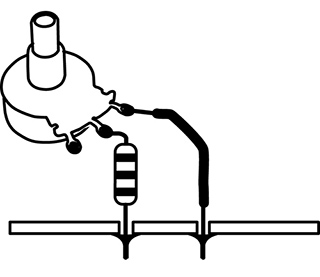
Figure 1 Potentiometer and fixed resistor in series.
To make the clock only go faster you connect the pot in parallel to the on-board resistor (essentially substituting it for your finger in the test we did in chapter 12): leave the resistor in place in the circuit, and solder wires from the two tabs of the pot to the two pads at the ends of the resistor (see figure 2).
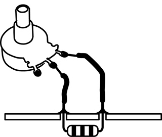
Figure 2 Potentiometer and fixed resistor in parallel.
To make the clock go slower and faster you remove the on-board resistor entirely and connect a pot of larger value than the removed resistor in its place (see figure 3).
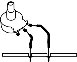
Figure 3 Potentiometer alone.
Finally, if you want the toy to go slower and faster but never crash, put the original resistor in series with the pot with clip leads (as in figure 14.1), then substitute progressively smaller resistors for your original value until you find one that lets the circuit run at the maximum speed without crashing, with the pot in the fully clockwise (i.e., 0Ω) position.
If all this doesn’t make sense in the abstract, check it out. Use the meter to measure some series and parallel combinations of fixed resistors. Then try some of these pot and resistor variations to a toy clock circuit until you feel comfortable with The Law.
Theory class is over.
Switches
How to Uunderstand Different Switches, and Even Make Your Own
You will need:
- An electronic toy or other sound-making circuit.
- Some hookup wire.
- A Single-Pole Double-Throw switch (SPDT), momentary or toggle.
- A plank of wood, some short nails, and a large ball bearing.
- Soldering iron, solder, and hand tools.
Switches are useful for turning power on and off to a circuit to save battery life, for turning on and off specific sounds or functions, and for resetting a circuit if it freezes up. They are often described in catalogs, on Web sites or in packaging by arcane abbreviations. Here are the main distinguishing features.
Mechanical Style
A switch can be momentary pushbutton, like a door bell, that changes state (turns something on) when you press it, and returns to its default state (off) when you release it; or it can be a push-on/push-off switch that alternates but holds its state. It can be a toggle switch with a lever, like a traditional light switch, that stays where you put it until you switch it back (usually). There is also the rotary switch, like the cycle selector on a clothes washer or the pickup selector switch on a Stratocaster, with which you choose between several positions, rather than just on and off. Slide switches, like the rotary switch, can select between two or more positions. There are a few other oddball switches we’ll discuss if they become relevant.
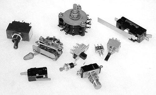
Figure 1 Assorted switches.
Number of Throws
A switch is also described by the number of mutually exclusive connections it makes when moved or “thrown.” A simple pushbutton that turns something on in one position, but does nothing in the other (beyond turning off), is called a “Single Throw” (ST) switch (see figure 2a). If the switch alternates between two possible connections, it is a “Double Throw” (DT) switch (see figure 2b)—this could be a pushbutton, a toggle, or a slide switch. Rotary switches that can make several different connections are classified by the number of connections, i.e., a five-position switch would be abbreviated as “5T” (see figure 2c).

Figure 2a: Schematic representation of a Single Throw (ST) switch.

Figure 2b: Schematic representation of a Double Throw (DT) switch.
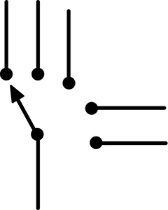
Figure 2c: Schematic representation of a Five Throw (5T) switch.
Number of Poles
Sometimes a single lever or button can switch two or more separate circuits simultaneously (think of the huge double-bladed switches in Frankenstein, thrown by one ominous handle). Most pushbutton and toggle switches are either “Single Pole” (SP; see figure 3a), meaning that they switch only one circuit, or “Double Pole” (DP; see figure 3b), which switches two circuits. The dotted line on the schematic representation indicates that the two sections switch in tandem. But switches can have three, four or more poles – they’re just less commonly encountered.

Figure 3a: Schematic representation of a Single Pole (SP) switch.
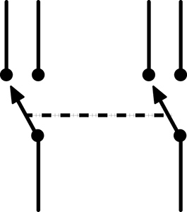
Figure 3b: Schematic representation of a Double Pole (DP) switch.
Terminal Designations
In a Double Throw switch the solder terminal that is normally off, or unconnected, is designated “Normally Open” (NO). The one that is normally on, or closed, is the “Normally Closed” (NC). The terminal that is connected, by the movement of the button or toggle, alternately to the NO or NC terminals is the “Common” (C; see figure 4).

Figure 4 Switch terminal terminology: “NC” = Normally Closed, “NO” = Normally Open, “C” = Common.
Reset Switch
You may have noticed that a bent toy occasionally freezes up, usually when the clock is run too high or too low, or you short out some part of the circuit. As per the 12th Rule of Hacking, momentarily removing the batteries will usually fix the problem. But this gets tiresome. The problem is that most modern toys do not have mechanical on/off switches – like televisions, they are usually only asleep when you turn them off. Current is still flowing through parts of the circuit, and the toy – like your computer – will not truly reset without really powering down and back on.
We can add a reset switch that lets you press a button or throw a toggle to disconnect the batteries temporarily, without the bother of actually removing them. You’ll need a SPDT (Single Pole Double Throw) or DPDT (Double Pole Double Throw) switch. It can be a momentary switch, if the toy already has a built-in power on/off switch; if you want to use the reset switch as a power switch as well, then get a toggle switch instead.
Cut one of the two wires connecting the batteries to the circuit board. Solder one end of the cut wire to the switch’s Common terminal (C); solder the other end to the Normally Closed (NC) terminal. If the battery wire is very short you may want to extend one or both sections with some additional hookup wire. If the switch has more than three connectors, or they are unmarked, you should use a multimeter to figure out the switch logic.
With a momentary switch, the switch is normally closed, so the battery voltage flows into the C terminal and out through the NC terminal to the circuit; when you press the switch the C flips its connection to the NO terminal, breaking the connection to the NC terminal and disconnecting the batteries from your circuit. Next time your circuit crashes, return the clock speed pot to a middle setting, restore any other weird connections to their “safe” states, press the switch for a few seconds, and (hopefully) the circuit will “re-boot” when you release it—easier than removing the batteries, especially in front of a restless crowd at CBGBs or The Royal Albert Hall.
If you use a toggle switch the circuit will stay in the off state when switched, so it will function as a power on/off switch as well, saving battery life offstage.
Toggle or momentary switches can also be used to switch on and off any resistive jumpers you insert in a bent toy, to switch between a fixed clock resistor and a variable one (or between two different variables resistors – such as a pot and a photoresistor), to select between different output signals, etc.
Homemade Switches
Switches are useful, often essential, things. Unfortunately, they can also be the most expensive part of a hack: resistors, capacitors, wire, and many other electronic components you use in hacking typically cost fractions of a penny, but a switch can set you back a few dollars/euros. However, with a little mechanical ingenuity you can fabricate your own switches out of paperclips, springs, brass fasteners, and other scraps of metal—classic prison technology, like making a shiv from a bedspring. It’s more of a mechanical problem than an electronic one: find two pieces of metal that conduct electricity, then figure out a practical way to move them in and out of contact with one another.
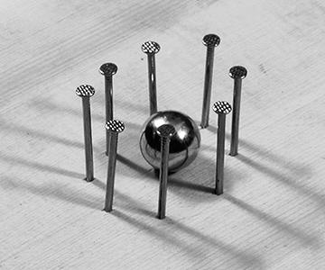
Figure 5 A homemade tilt switch.
You can construct a nice multi-position tilt switch by hammering a ring of brads into a piece of wood, soldering a wire between each nail and a point on the circuit board that needs switching, and dropping a big ball bearing into the corral (see figure 5). You can use this switch to select different circuit jumpers in a bent toy, or switch between the outputs of several toys to feed the input of your amp. Variations on this design can be made with loops of wire, strips of copper, or even blobs of mercury (once a common switch element, now banished behind the sign of a skull and crossbones—see figure 6).
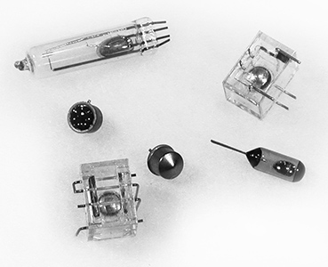
Figure 6 Some commercial tilt switches, using ball bearings and deadly blobs of mercury to connect contact points.
Jack, Batt, and Pack
Powering and Packaging Your Hacked Toy
You will need:
- A finished circuit or bent toy.
- A battery-powered mini-amplifier.
- Some hookup wire.
- One or more jacks for external audio connection.
- Some 1kΩ resistors.
- A battery holder (if appropriate—see text).
- A box of some kind to house your circuit.
- Soldering iron, solder, and hand tools.
In the midst of bending a toy or soldering a circuit it’s easy to lose sight of the light at the end of the tunnel: an artfully encased object that will elicit awe from your friends. Here’s some advice on getting the rat’s nest off the bench and into the real world.
Jacks
Beyond retuning the clock and finding some musically viable almost-shorts, the most significant change you can make to a bent toy is replacing the little speaker with a big one, thereby confirming the Second Law of the Avant-Garde (make it louder). A coil pickup resting on the little speaker is one approach, as discussed in chapter 6. But if your circuit is never going to be played by saliva-drenched fingers it’s safe to wire a connection directly to an amplifier – a bit more preparation work than slapping the coil down, but ultimately cheaper and faster to patch together in performance.
By adding a jack to connect the circuit to an external amp and a decent-size loudspeaker you not only make the sound much louder, which lets you hear more detail, but you will also hear low frequency components that aren’t audible through the tiny, parent friendly speakers inside most toys. And everyone wants more bass. It’s easy to do:
- Find the wires leading from the circuit board to the speaker.
- De-solder them from the speaker terminals or cut them as close to the speaker as possible.
- Solder these two wires to a female jack of your choice; usually it doesn’t matter which wire goes to which terminal, but you must always have one wire going to the shield/sleeve connector and one to the hot/tip connector.
- Plug into a decent sound system and listen. Start at a low volume setting, since the output can be surprisingly loud. If there’s lots of hum, reverse the hot and ground connection at the jack. If there’s no sound at all, check your soldering. You may find that the raw sound is too much—too noisy or abrasive, too much extreme high or low—but that’s where the equalization on a mixer, amp or graphic EQ “stomp box” can help you carve the sound you want out of your circuit’s raw material.
Let me repeat:
DO NOT ATTEMPT THIS MODIFICATION ON A CIRCUIT THAT WILL BE MAKING INTIMATE ELECTRICAL CONTACT WITH YOUR BODY (SUCH AS THE WET-FINGERS RADIO).
As long as you’re adding one jack, why don’t you see if there are any other interesting signals running around the circuit board yet unheard?
- Solder a wire from the shield/ground connection on a jack to the place on the circuit board where the “–” terminal of the battery connects, or to the shield/ground terminal on the main output jack, if you’ve added one already. Use stranded wire if at all possible – less strain on the connections at either end, and easier to pack into the toy’s case.
- Solder another wire to the hot tab of the jack and strip and tin the other end.
- Solder a 1kOhm resistor to the tinned end of this wire.
- Plug a cord between the jack and a battery powered amplifier.
- Turn the volume up just a little bit. Poke the free end of the resistor around the circuit board and listen to the different sounds (see figure 1). Adjust the volume as needed. Sometimes you can find very odd noises that seem completely unrelated to the basic sound of the circuit, especially with bent toys. Hold on to the body of the resistor, rather than the bare wire, to minimize hum.
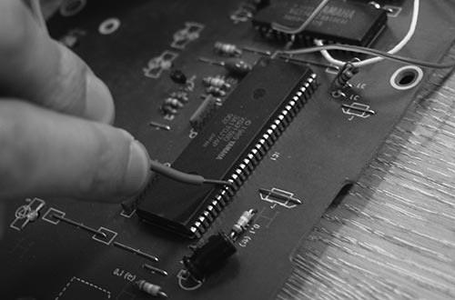
Figure 1 Phil Archer hunting for interesting sounds. Photo © Phil Archer, used by permission.
- When you find a place you like, solder down the free end of the resistor. Wrap the bare wire and resistor lead in electrical tape to prevent shorts (you can shorten the resistor leads prior to soldering to minimize the amount of bare wire running around your circuit, itching for a short circuit.
- If you wish, add another jack and repeat the process, discovering and decanting hidden sounds. Or add a multi-position switch (like a rotary switch or our homemade tilt switch) to select among different circuit points to connect to a single jack.
If you get sound when one or the other of your jacks are connected to the amplifier/mixer, but not when you combine two or more, you have probably unintentionally crossed your grounds. De-solder one of the two incompatible jacks from its wires (the speaker jack, if used, is the first choice) and swap the “hot” and “ground” connections.
Cut-out Jacks
You may have noticed that most audio devices with a built-in speaker and a jack for headphones (such as a boombox) will switch off the speaker automatically when the headphone plug is inserted. This is accomplished with what is known as a “cut-out jack,” which basically combines the functions of an audio jack and a switch, and can be purchased at almost any retailer carrying electronic connectors. The jack’s terminals will be designated “tip” or “hot,” “sleeve” or “ground,” and “normally closed” (NC —like the switches we discussed in the previous chapter). These designations might be printed on the jack’s packaging, provided in the retailer’s catalog or web site, or you might have to decode them using your multimeter in the Ohms setting. You wire it as shown in figure 2.
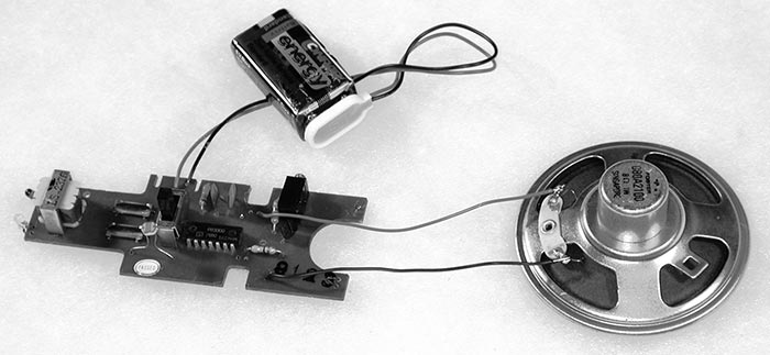
Figure 2 Wiring a cut-out jack.
- Solder a wire between the jack’s ground lug and the circuit ground, in parallel to the speaker’s ground connection (do not disconnect the speaker ground); or you can cut the ground wire in the middle and solder both ends of the cut to the ground lug on the jack (as shown in figure 2).
- De-solder the wire from the speaker’s hot terminal and solder it instead to the jack’s tip/hot.
- Solder a new wire from the speaker’s hot terminal to the NC terminal on the jack.
Turn on the circuit. You should hear the sound through the built-in speaker as usual. Now plug a cord from the cut-out jack to your amplifier—the speaker should shut off while the signal passes to your amp through the patch cord. If not, check your wiring logic and soldering joints—it’s easy to make a mistake.
VERY IMPORTANT:
BE VERY CAREFUL CONNECTING A HACKED CIRCUIT TO A MIXER OR AMPLIFIER THAT GETS ITS POWER FROM THE WALL. IT’S BEST TO TEST FOR ANY POSSIBLE ELECTROCUTION HAZARD BY GINGERLY TAPPING THE CIRCUIT BOARD, JACKS, AND POTS WITH A DRY FINGER AND FEELING FOR ANY BUZZ OR TINGLE. ALTERNATIVELY, LET A SQUIRREL RUN ACROSS THE BOARD.
And always remember the 14th Rule of Hacking:
Rule #14: Kick me off if I stick (Zummo’s rule)
Always have a buddy nearby when there is a risk of electrocution, and chant Zummo’s mantra before you power up.
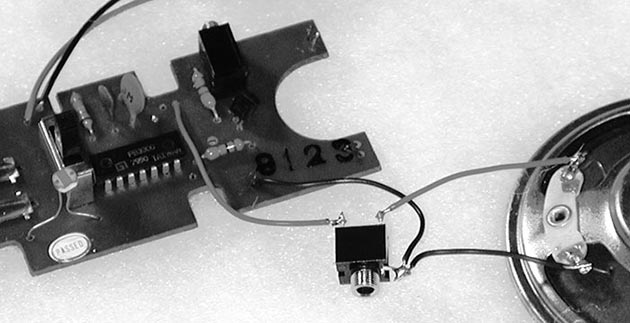
An excellent insurance against electrocution is to insert a DI box between your circuit and the AC-powered world – one of these can be purchased from retailers selling electric guitars, microphones, keyboards, etc. If you’re up for somewhat more advanced hacking, you can wire what is known as an “audio isolation transformer” between the circuit’s output and the rest of your sounds system (see figure 3). But if you are unsure of your hacks or the power grid, JUST STAY AWAY FROM ANY OUTLETS! Use a coil pickup on the speaker instead if you want to get loud.
Figure 3 Homemade stereo isolation box made with output transformers removed from an API mixer, Nicolas Collins.
Battery Substitution
This section is primarily of value in circuit bending. Almost all toys use batteries that put out either 9 volts or 1.5 volts. Most 9-volt batteries look the same: bricks with two connectors that resemble android navels (one innie, one outie). 1.5-volt batteries come in a plethora of packages: cylindrical ones, like D cells (the biggest kind, in the flashlights wielded by Southern sheriffs), C cells (a little smaller), AA cells (“penlight” flashlight batteries), and AAA cells (even thinner and a bit shorter, like some metric mismatch of an AA battery), and button cells (the watch and camera batteries that are infernally small, come in a zillion different sizes and shapes, and are way too expensive and hard to find). A few button cells put out 3 volts (inside the casing are stacked 2 tiny batteries), and there are some oddball batteries (like the one that looks sort of like an AAA but puts out 12 volts, often used in remote controls for garage doors), but the vast majority of batteries follow the above rules.
Nine-volt batteries are usually used singly, but 1.5 volt ones are often combined to add up voltage to power a circuit—commonly found in sets of two, three, or four. The larger (and heavier) the battery the more current it provides, which means it lasts longer and can power a larger circuit, so:
Rule #15
You can always substitute a larger 1.5-volt battery for a smaller one, just make sure you use the same number of batteries, in the same configuration.
This means you can replace those little button battery cells with the same number of AA cells and run the circuit much longer and much cheaper, and afterwards you can find replacement batteries almost anywhere. All you need to do is:
- Disconnect the existing battery holder, noting which wire connects to the “+” end of the battery stack, and which connects to the “–” end (look at the labeling on the batteries or holder, or measure the voltage with a meter).
- Get a battery holder for larger batteries of your choice.
- Connect it to the circuit, observing the proper polarity of the wires you de-soldered earlier.
Some low-current 6-volt circuits (i.e., using four AA, AAA, or button cell batteries) will run on a 9-volt battery, and might even react to the additional juice with extra perkiness, but others will succumb to cardiac arrest. Unfortunately there’s really no way to know until you try it, so proceed with caution (and a duplicate circuit, if at all possible) and disconnect the new battery if you smell smoke or feel a component on the circuit board getting hot.
As you accumulate circuits you will be tempted to minimize your energy costs by using a single battery (or set of batteries) to run several devices. This, unfortunately, is notalways a good idea: sharing often induces noise, weird interference, and interaction, especially if you try to connect more than one of the circuits to the same amplifier.
Rule #16
It’s always safer to use separate batteries for separate circuits.
How big a battery to upgrade to has as much to do with fitting them inside the device as any electrical consideration, which brings us to our next topic.
Packaging
As your first hack nears completion you’ll want to think about how to package it. You have a few basic style choices:
Stealth: Keep the original packaging, with added knobs, switches, and jacks, as needed (see figure 4 and 5).

Figure 4 Stealth packaging: bent keyboard by Alex Inglizian.

Figure 5 Stealth packaging: bent Chinese language trainer by Nicolas Collins.
Camp: Go for other recycled housing, such as a cigar box, a cereal box, or a human skull (see figure 6). David Tudor favored plastic soap boxes. After the rise of the DVD and streaming services, plastic VHS boxes filled the dumpsters outside rental shops and the attics of elderly relatives, and they make perfect homes for circuit boards (see figure 8). Cigar boxes are great because they can usually be had for free, and you can open them easily to change batteries or touch the circuit. If the clock speed is controlled by photoresistors inside the box, the pitch will glide up and down as you open and close the box, like a cubist trombone. Unfortunately, the wood of a cigar box is usally just a little too thick for most jacks and pots to mount easily—you may need to countersink the mounting holes in order to secure any nuts that screw down; alternatively, you can pass shielded cable through holes in the wood and solder plugs or jacks directly to the ends, and end up with a cigar box octopus. Altoid tins are good for small circuits (they hold a 9-volt battery neatly), but since they are made of metal you must make sure the circuit does not short out against the case – the discrete application of electrical tape to the bottom of the circuit board or the inside of the tin should do the trick (a sheet of thin cardboard works too); one can also buy plastic standoffs for this purpose. You can see Altoid tins in action throughout this book, the legacy of my son’s obsession with sweet breath.

Figure 6 Camp packaging: circuit inside Pringle tube by André Bosman.
Sandwich: Two slabs of acrylic plastic or thin wood with a circuit board in between (see figure 7). Fast to make, and clear plexi lets you see what’s going on inside.
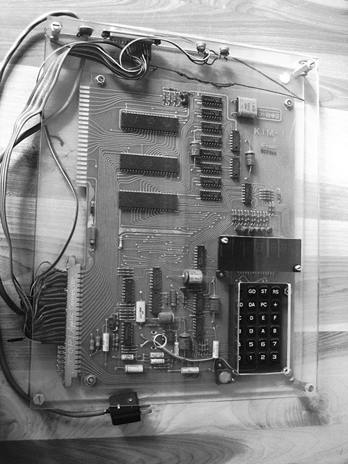
Figure 7 Vintage sandwich packaging: David Behrman’s “Kim 1” microcomputer, c. 1977. Photo © David Behrman, used by permission.
Traditional: One of those plastic or metal boxes that make your product look “professional” (or boringly geeky, depending on your perspective; see figure 8). Remember that a bare circuit board will short out if placed in a metal box unless it is isolated from the metal, as mentioned for the Altoid tin, above.
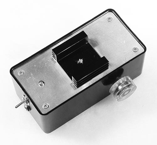
Figure 8 Traditional boring packaging: small amplifier by Nicolas Collins.
The decision is partly topological (how do I fit in the circuit, jacks, pots, and switches?), partly practical (what’s the easiest material to drill?), but largely aesthetic (what looks coolest?).
Now that your first hack is resting comfortably in a beautiful box, the time has come to show it off. Get out of the shop, pick up the phone and book that gig! Or at least upload something to YouTube.
Power Supplies
Carbon Footprints from AA to EEE
You will need:
- A DC wall-wart plug-in power supply.
- A diode, 1N4004 or equivalent.
- Some capacitors: 0.1, 100uf and as big as possible.
- A fixed-voltage positive regulator (LM7809 or LM7812).
- An LM317 variable voltage positive regulator
- Hand tools, test meter, and soldering iron.
- A breadboard on which to test your circuit.
- A solderable circuit board on which to assemble your circuit.
- Some solid and stranded hookup wire.
- A few solar cells
- Some fruits and vegetables
- Spare change, paper towel, salt, water
- A bicycle dynamo or small DC motor
Oh dear, I feel like a father enrolling his son in a driver education class or explaining safe sex: I wish we could stop here, but one day you will leave home and must be prepared for the big world.
Although the Second Rule of Hacking barred you from touching an AC power cord, the time will come when batteries simply will not suffice. You will tire of the cost of replacing them, and the accompanying environmental guilt (although these concerns can be minimized by rechargeable batteries), or you will build a circuit that draws so much current that it drains the battery flat before you can say “Union Carbide.” You will have to choose between living a long and virtuous (but possibly slightly constrained) life that adheres strictly to 25-fold path of the Rules of Hacking, or enjoying the risky heretic pleasures of power supplies. As a stopgap solution to exposing your hands and heart to lethal voltages, you can advance to the ubiquitous “wall-wart” that powers so many domestic appliances these days (see figure 1).
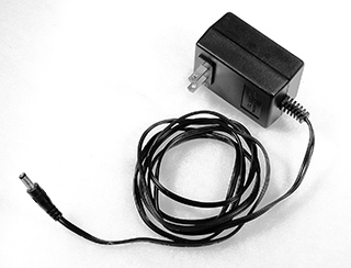
Figure 1 A typical wall-wart power supply.
The power grid in North America delivers to your outlet a sine wave that fluctuates between 0 and 120 volts 60 times per second; in Europe, 240 volts at 50 cycles per second, and in Japan 100 volts at 50 cycles. If you plugged a very strong speaker directly into the wall (not recommended, by the way), you would hear a loud, low pitch around 2 octaves below middle C. The wall-wart consists of a transformer encased in plastic and wired directly to an AC plug. The transformer takes the 100/120/240 volts of alternating current (AC) and steps it down to the nonlethal range suitable for powering electronic circuitry. The advantage of the wall-wart supply is that the dangerous voltages remain (in theory) within the plastic lump, and the ends of the wires present a mild, relatively safe, more battery-like voltage. The traditional power supply found inside your TV or guitar amplifier, on the other hand, brings the wall voltage right into the chassis, where it can easily be touched (ouch!) as you tinker. So, if you must use the electrical grid, let the wall-wart be your condom.
You can find wall-warts everywhere, often very cheap. Since the physical construction of the thing is an indication of the quality of workmanship inside, you are advised to select one that looks pretty solid, with no holes, cracks or wobbly parts (just keep my French Letter analogy in mind – without smirking, please).
There are two basic types of wall-wart. An AC wall-wart consists solely of a step-down transformer; it puts out a low voltage 60/50hz signal, which must be further conditioned to make it useful for powering circuitry. A DC wall-wart contains some additional circuitry (a few diodes and a big capacitor) required to smooth out the fluctuating signal into a voltage that more closely resembles the steady DC output of a battery.
The wall-wart should be marked with the following information:
- The primary voltage that the wall-wart can be plugged into, i.e., 120 (North America) or 240 (Europe) volts AC (VAC). Many modern wall-warts (such as those provided with most cell phones and laptop computers) handle any input voltage between 100 and 240 volts. Choose the appropriate primary voltage for the country in which you are working if you can’t find one with a “universal” prinary.
- The secondary voltage that appears at the loose end of the long dangling wire (or built-in jack), usually in the range of 3–24 volts. Some wall warts include a switch for selecting amongst different output voltages. We need a secondary voltage between 6–15 volts.
- Whether it has an AC or DC output. We need DC.
- The amount of power the transformer can provide, usually measured in watts (W), amps (A or MA), or volt-amps (VA). We want a transformer that puts out a minimum of 100 milliamps (ma), which may be indicated as 0.1 amps or 5–10 watts.
For example, a wall-wart might be labeled “120vac input, 12vdc output, 200 ma.”
Built into the plastic casing should be a power plug appropriate to the outlets in your country. In some instances the wall wart is more like a rug rat, with a power cord instead of a built-in plug; sometime this cord is attached to the plastic lump, and sometimes it plugs into a socket of some sort. If there’s no output jack, two wires should emerge from the other side of the wart: they may be a parallel pair, like speaker cable or lightweight lamp cord, or may be shielded cable, with one conductor wrapped around the other. At the end of this cord will be one of a zillion different types of minimally distinguishable little plugs – usually some form of tortiglioni-like “coaxial power connector”. Some cables terminate in a system of interchangeable connectors of different style.It’s convenient if the plug matches some loose female jack you have in your parts collection, or one you can buy locally. It’s risky to buy one part or the other sight unseen: never trust measurements on packaging, always test that the male and female connectors fit together snugly. On the other hand, matching connectors are not essential: you can always cut off the plug and connect the bare wires directly to your circuit, or solder on a new plug from a matching plug and jack set you acquire elsewhere.
When adapting a battery-powered circuit to be powered by a wall-wart you must observe two critical factors:
- The wall wart’s voltage must be within the two limits we described above (i.e., greater than 6 volts but less than 15 volts), but the current capability can be anything higher than the minimum need to power the circuit. For example, a circuit requiring 20 ma can be powered by a supply producing 20 ma, 100 ma, or 1000 ma. The circuit will only draw as much current as it needs (sort of like having an oversized gas tank in a car you only use to go shopping around the corner.)
- Check the polarity of the secondary connector or wires: you must know which is “+” and which is “–” before connecting the wall-wart to your circuit, or catastrophic pyrotechnics may result.
Sometimes the wall-wart will be marked with information specifying which part of the connector is “+” and which is “–”. Sometimes one of the cables will have a convenient white stripe that distinguishes it from its mate. But it is always safer to confirm the polarity with a multimeter.
Set the meter to measure “DC Voltage.” One probe plugs into the meter’s “ground” or “-” input, while the other connects to something probably marked “voltage” in red. Touch one probe to one part of the connector, and the other to the other; if you’ve already removed the connector measure between the ends of the stripped wires. If the meter reads out a voltage with no prefix (i.e., “13.6”), then the wire/connector touching the ground probe is the “–” output, and the other is the “+.” But if the meter puts a “–” before the number (i.e., “– 13.6”), you know that the connections are reversed, that the wire touching the minus probe of the meter is actually the “+” output and the other is “–.” Confused? Try this test on a nice familiar (and safe) 9-volt battery. Then test the wall-wart again.
Once you figure out which wire is which, mark them carefully: scribble a drawing of the connector with appropriate + and – markings, or wrap some colorful tape around one wire. If the output voltage of your wall-wart measures less that 15 volts DC you can connect it more-or-less directly to your circuit. You can either use the matching connector to whatever plug is attached to the wall-wart’s cord, or you can cut off the plug and solder the wires directly to the board. Double-check the polarity before you plug it in!
Cheap wall-warts will usually have some “AC ripple” in their voltage output—a sign of skimping on parts in the conversion from AC to DC (you usually don’t get what you don’t pay for, I’m afraid). A circuit powered with such a supply may hum – under its breath or quite loudly, depending on the quality of the wart. If you alternate between a battery and wall-wart powering the same circuit you should be able to hear the difference. Until you get good at designing or choosing better power supplies, a battery will usually sound cleaner. One easy fix that usually helps is to add a big capacitor, say between 100–10,000uF, between “+” and “–” supply on your circuit board. As mentioned in chapter 18, big electrolytic capacitors have polarity, like a battery, which is marked on the body. Make sure you connect “–” to the ground bus, “+” to “+” supply. Placing an additional 0.1uF capacitor between the “+” and ground supply pins very near each chip also helps lower noise and reduce “crosstalk” between different parts of your circuit. Both these capacitors can be seen in figure 2.
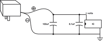
Figure 2 Basic filtered power supply
A quick measurement with a meter will show that even though a wall-wart might be marked “12 volts DC” in bright white letters, it could put out anything from 10 to 20 volts. The CMOS chips used in most of our circuits were chosen in part for their forgiving nature, but they have their limits—upper limits: they can run on power supplies from 3 volts to about 18 volts, but above 18 volts they can expire quite dramatically. A 9-volt battery sits comfortably between these two extremes. If you choose to use a wall-wart instead of a battery always measure its actual output voltage and polarity before connecting your circuit—don’t rely on the markings on its case.
Rule #25: Never trust the writing on the wall-wart.
Alternatively, for a really quiet, reliable supply you can add a simple integrated circuit called a “voltage regulator” (see figure 3). A regulator filters out the last of the AC ripple and sets the voltage to a precise level, which is specified by the last two digits of the chip’s part number: 7812 = 12 volts, 7809 = 9 volts, 7805 = 5 volts, etc.
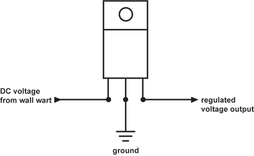
Figure 3 78XX-series voltage regulator pinout.
The input to the regulator must be at least 3 volts higher than it is expected to put out (i.e., 12 volts in for 9 volts out), and no higher than about 25 volts; so measure the output of your wall-wart with your meter to make sure it is within these limits. You can get regulators for a wide range of output voltages – the 7809 is a shoe-in for the 9-volt batteries we’ve been using, but the 7812 and 7805 are more commonly encountered, and our CMOS chips should run fine on any of these three. The basic design shown in figure 4 works for any 78XX series regulator. It’s normal for the regulator to get a bit hot—bolt the regulator’s tab to a piece of metal to dissipate the heat (or you can buy yourself a fancy finned heat sink).
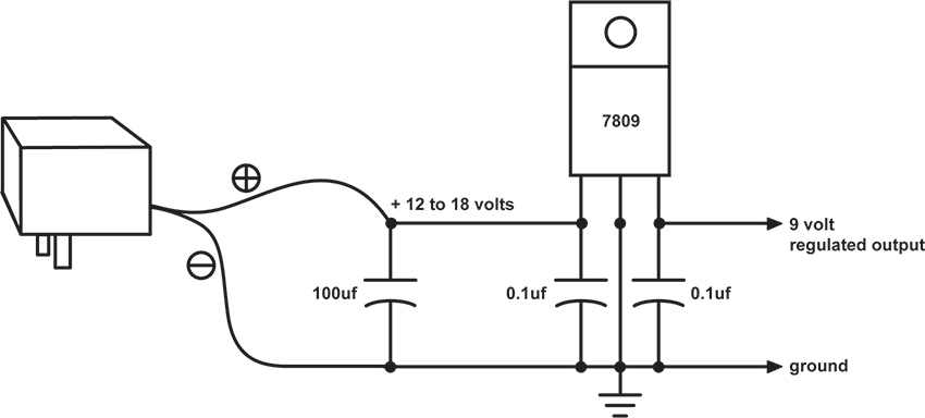
Figure 4 A simple regulated power supply.
If you have had success with the voltage starve-circuit we described in chapter 15 (figure 15.13) you can implement it with a wall-wart, with or without regulator, feeding the pot just the same as a battery. Or you can build a power supply whose output voltage can be adjusted quite precisely, using a slightly different regulator, the LM317T see (pinout in figure 5). The potentiometer in the circuit shown in figure 6 lets you adjust the voltage anywhere between about 1.2 volts and almost the voltage coming out of the wall-wart. The LM317 looks the similar to the 78XX regulators, with three legs, but the connections to the pins are different, so double-check your wiring before plugging in the wall-wart.
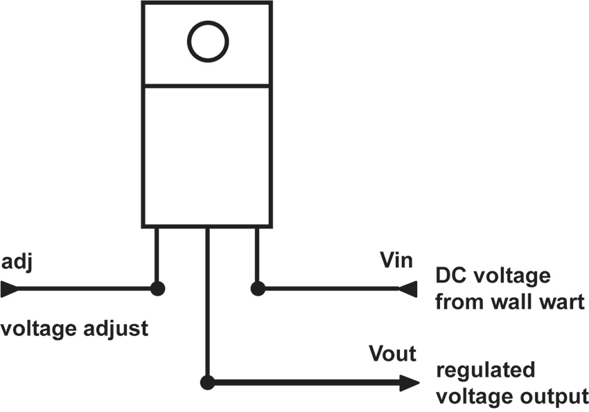
Figure 5 LM317 Voltage Regulator pinout
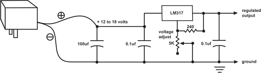
Figure 6 Variable voltage power supply with LM317
Going Green
If you feel like kicking your Duracell habit, but also want to stay off the grid, consider some alternative power suggestions that will reduce your carbon footprint to smaller than the business end of a stiletto heel. The obvious first step, as I suggested way back in chapter 1, is to invest in some rechargeable batteries in lieu of the disposable kind. The newer NiMH (Nickel-Metal Hydride) batteries are much more efficient than any alkaline cell, packing more current (i.e., run time of your circuit) into a lighter package. They are available in many configurations, from AAA to D, as well as 9-volt. You can charge them quickly in any AC outlet, or invest in a solar charging unit.
Speaking of solar, there’s no reason – aside from cloud coverage – that you can’t power your circuits directly off old Sol. Solar power panels are abundant these days, and they are decreasing in price as they increase in power. You can sometimes buy one that substitutes directly for a battery or wall-wart, providing 5-12 volts at 500 milliamps or more of current (check out marine supply stores). But they can be a bit pricey. A more economical (and educational) alternative is to seek out – usually on-line -- the individual cells that make up these panels. The cells are rated for voltage and current output. They have a pretty low output voltage – usually around 1.5 volts – but come in a wide range of current ratings, typically a function of the size (see figure 7). Sometimes the cells are combined to add up to higher voltage. Pick a model whose current is sufficient for your circuit needs – 100 milliamps (ma) is sufficient for most of our circuits, 500ma if you’re powering a small amplifier, like the LM386 from chapter 24, as well. Then buy enough to add up the voltage you need for you circuit. Bearing in mind that the CMOS circuits we’ve been powering on a 9-volt battery can run on voltages as low as 3 volts, you may be able to get away with only a handful of cells (see figure 8).

Figure 7 Assorted solar panels (center unit with rechargeable batteries attached)
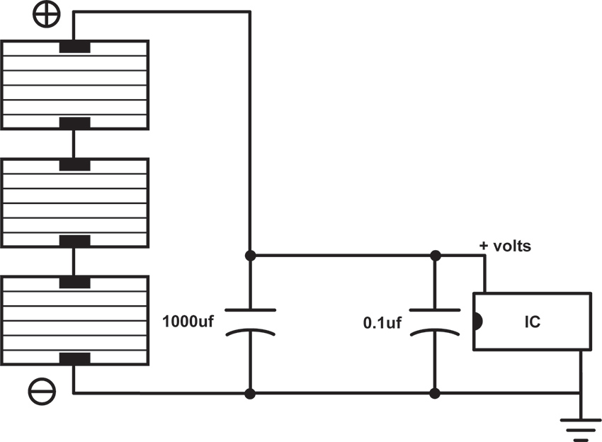
Figure 8 Direct solar power of a circuit by adding voltage output from multiple solar cells
A critical component in figure 8 is the capacitor. Remember how, in chapter 13, I compared the capacitor to a bucket? In this circuit the capacitor is your canteen in the desert, tiding you over between oases (or a cistern collecting rainwater so you can continue to shower after the storm has passed). The capacitor acts a little bit like a rechargeable battery whose strength is proportional to its size in uf. Without it the circuit responds directly to the amount of light present: when the sun shines the circuit runs; when a cloud passes the circuit shuts off. If we insert a medium size capacitor, say 1000uf, it will retain enough energy to bridge the gap caused by a scudding cloud, but not enough to keep it running overnight. If we get an insanely large capacitor, say around 1 farad (not micro-farad), such as are used in memory backup applications, it holds the charge much longer, acting much more like a rechargeable battery. Finally, we can substitute actual rechargeable batteries (usually a set 1.5-volt cells stacked to add up to your desired voltage) for the capacitor, and modify our design slightly, as shown in figure 9. At this point whatever we hang off this circuit is really being powered by the battery, not the sun, and the battery is in turn being “trickle charged” by the sun, weather permitting. Be sure that the series voltage of your photocells is greater than the battery voltage, or the batteries won’t charge, and less than the maximum voltage for the circuit (i.e., 15 volts), or the chip might fry.
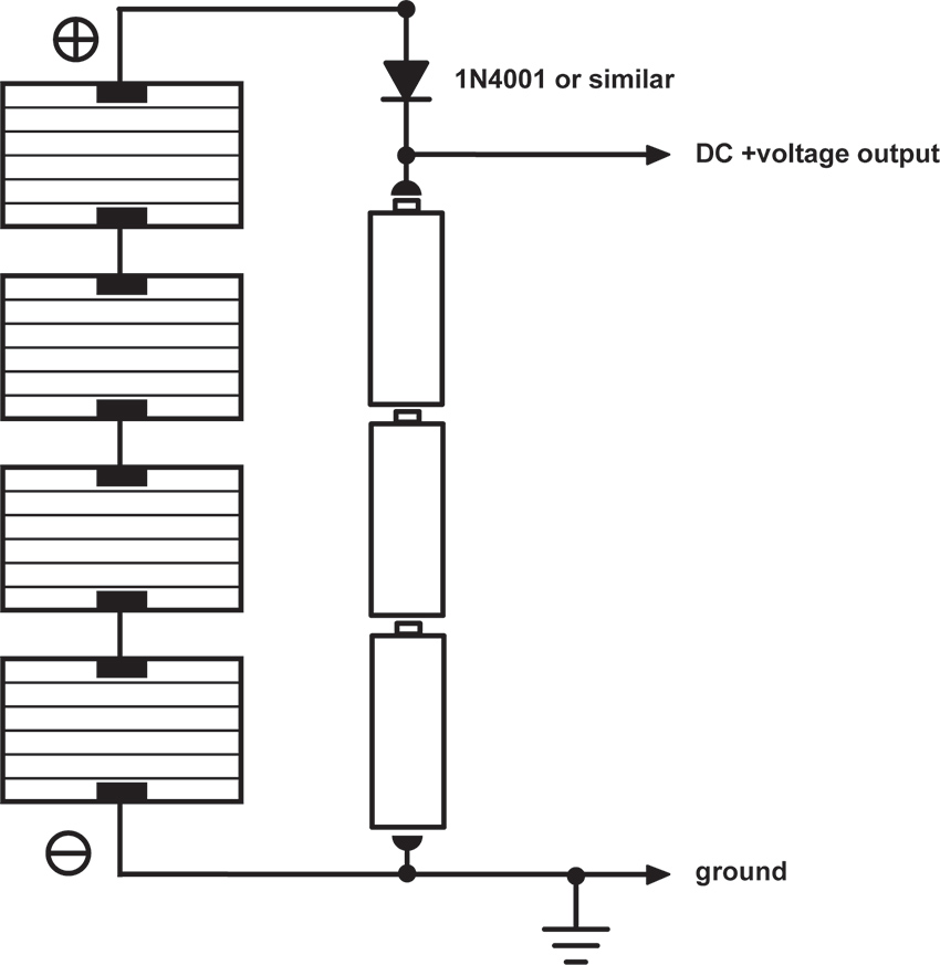
Figure 9 Solar-powered battery charging circuit
As on a few other occasions in this book, I should explain that figure 9 is a simplified design. Proper battery chargers can get quite complex -- these days many incorporate microprocessors that regulate the charging current and monitor the cell’s condition to minimize the charge time and maximize the battery’s lifetime. If you are serious about the long-term survival and performance of your project you should consider either springing for a commercially available solar-powered battery charger, or type those key words into Google and spend a few minutes downloading schematics by people who know more about this arcania than I do.
My First Bio-fuel
The older among you, with dim memories of grade school science fair projects with potatoes and nails, might be wondering about the possibility of building your own battery with the contents of your crisper bin. Not only can it be done, but with proper lobbying you might convince Congress to subsidize your efforts to free American electronic music from the shackles of oil and coal.1
The potato battery functions on the same basic chemical principle as a traditional battery: when two strips of different metals (typically copper and zinc) are inserted into an acid solution (in this case the liquid in the potato’s cells) an electrochemical reaction takes place, which generates a potential difference between the metal strips. A pair of electrodes (as the metal strips are called) inserted into a potato will generate around 1 volt at a very small current. Individual bio-cells can then be added in series and parallel to produce higher voltages and more current.
A copper penny or strip of copper wire can serve as your positive electrode, and a galvanized nail for the negative one. Insert them into a potato, lemon, or apple, and measure the voltage with a multimeter. Put several electrode pairs in series as shown in figure 10 -- you can use a separate vegetable or fruit for each pair, or insert multiple electrodes in a single large tubor. Make sure none of the electrodes touch each other. A quick check with the meter should confirm that your power station is putting out around one volt per potato. You can connect an LED and, if the orientation is right, it should light up. Hook up your new battery to a simple oscillator circuit and see if it runs. If it doesn’t you might need to add a few more potatoes in series to increase the voltage, or in parallel if your circuit requires more current.
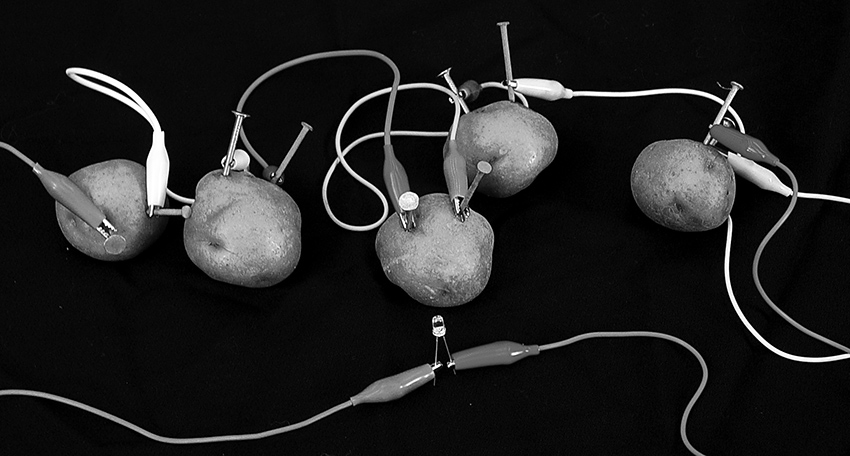
Figure 10 Adding multiple potato cells in series to increase voltage
The voltage output of this kind of battery is a function of the metals used for the electrodes, rather than your choice of produce: copper and zinc (present in galvanized hardware) yield about 1.1 volts per cell. Substituting magnesium for the zinc increases this to about 1.6 volts (I’m not sure what the most convenient source of magnesium scrap would be). The lifetime of your battery is primarily a function of how long it retains its moisture, so you might experiment with more succulent options, such as lemons, grapefruit, etc. And do bear in mind that these earthy batteries put out a very small amount of current – if you’re lucky our low-power CMOS oscillators will whistle comfortably on potato juice, but don’t expect to run an amplifier or motor this way.
In chapter 13 we discussed using bits of vegetables and fruits as alternative resistors in toy clocks and oscillators. The resistive character of these materials is primarily a function of their moisture content, although we can speculate now that their electrolytic interaction with the wires we used to make the connections might also influence the behavior of our circuits: two wires of the same metal (i.e., copper) should not induce voltage, but different metals can. You might experiment with the contents of your garden for both a power supply and a timing component in your circuits. Too bad we can’t grow our own chips…. (David Tudor once told me a story of a Brazilian electronic music composer who, in the early 1960s, was making his own transistors by baking crystals in his oven but, sadly, I was not able to follow up this lead before Tudor passed away.)
One last observation: the voltage output of these bio-batteries is not as steady as your basic Duracell. In fact, the chemical process at play generates a fair amount of noise – a capacitor added to our power supply circuit should smooth this out if it’s problematical. On the other hand, if instead of connecting the electrodes to a circuit or LED you wire them to the tip and sleeve of your headphones, you can listen directly to the crackly sound of a singing potato. Not loud enough? Connect to electrodes to the input or your amp or mixer, and turn it up.
Kitchen Sink
As long as you’re rummaging about in your refrigerator for fruit and vegetables, you might scan your kitchen for some paper towel and salt. As Cy Tymony has shown in his wonderful book, Sneaky Uses For Everyday Things, you can build potato-like batteries from nothing more than spare change, wet paper towel, and table salt. Each cell requires one penny and one nickel, for the copper and zinc electrodes respectively (sorry, Euro-toting hackers, you’re out of luck). You can solder a wire to each. Fold a piece of paper towel into a coin-sized pad, dampen it, sprinkle it with salt, and sandwich it between your coins. Measure the voltage between the two electrodes and it should be in the potato range. The clever thing about this style of homemade battery is that you can just stack your change in a folded strip of paper towel to build up whatever voltage you want, rather than digging up a fresh spud for every volt. Wire cells in parallel to increase the current capacity.
Hand Jobs
For the ultimate in self-sufficiency consider combining alternative energy resources with a physical fitness regimen. A generator is a device convert repetitive mechanical motion into electricity. Most function electromagnetically, and bear the same relationship to an electric motor as a microphone has to a speaker: spinning a shaft rotates a coil in a field of fixed magnets, inducing a current flow (remember using a motor to generate sounds in chapter 4?). Traditional power plants use coal-, oil-, or gas-powered turbines to spin these generators; hydroelectric dams channel water past turbine blades; wind farms are popping up all over. Older Dutch hackers will immediately think of the whirring little dynamo on the front wheel that powered pre-LED bicycle headlights – these can easily be adapted to stationary exercise bikes, skateboards, egg beaters, spinning wheels, fishing reels, water wheels, windmills, steam engines, etc. Whether a response to soaring energy prices, or merely a green affectation, generators are showing up in a number of common consumer products: flashlights that light when you squeeze or shake them, radios and laptops with hand-cranks, etc. The generator element can be removed from any of these devices and re-wired to power your circuit.
As you might infer from the interchangeability of speakers and microphones, any DC motor can be used as a generator: connect the motor terminals to an LED, spin the shaft, and see the light (see figure 11).
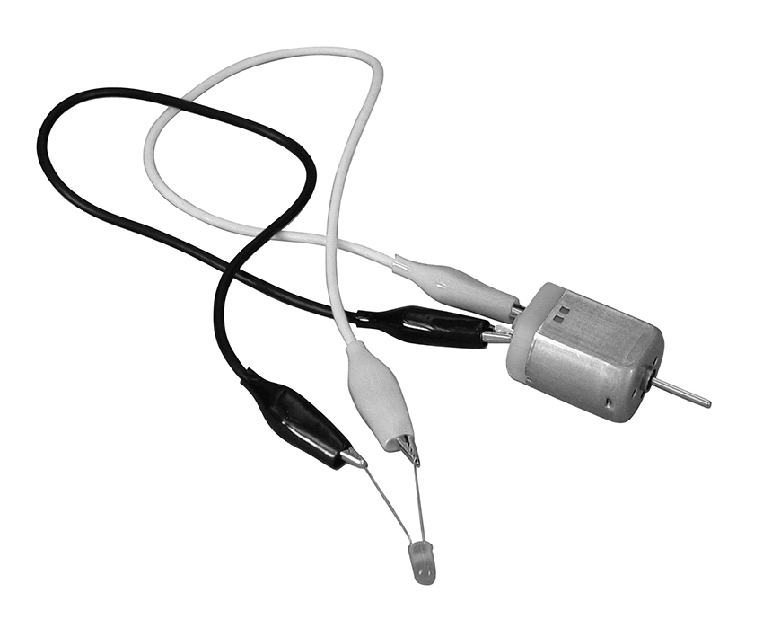
Figure 11 Motor-as-generator: spin the shaft and watch the LED light
As with our solar circuits, the critical factor is smoothing the erratic output of the generator so that the circuit doesn’t shut down when you park the bike, or the wind dies down. The solutions are basically the same as those shown elsewhere in this chapter: add a big capacitor, or configure the generator as a charger for a rechargeable battery. Then again, of you had interesting results from the voltage starve circuit you may find that a relatively unfiltered generator makes a good “performable power supply”. Ithai Benjamin’s and Alejandro Abreu’s “Synthinetic” (see figure 12 and their video on the website) and Phil Archer’s “Music Boxes” (see his video on the website) are lovely examples of this type of power supply in action.
Figure 12 “Synthinetic” by Ithai Benjamin and Alejandro Abreu, using motor as generator. Photo © Ithai Benjamin and Alejandro Abreu, used by permission
1 Written before the rise of the Trump regime, preserved out of naïve hope for a better future, eventually.