Online Resources
Project Support
Sharing Traces
Designing and Fabricating Your Own Printed Circuit Boards (Eduardo Rosario): Data files for Fritzing and Eagle projects
Download Data files for Fritzing and Eagle projects (ZIP 125KB)
Sharing Traces
Designing and Fabricating Your Own Printed Circuit Boards with Eagle (Eduardo Rosario)
This is an extension of chapter 32 in the printed book, “Sharing Traces: Designing and Fabricating Your Own Printed Circuit Boards with Fritzing.” Here we will shift our focus from Fritzing, a popular hobbyist/hacker application, to Eagle, one of the “industry standard” software packages.
Autodesk’s Eagle is one of the standard EDAs used by professional electronic engineers and amateurs alike. As a hobbyist you can download a free version of Eagle—a Personal Learning License for individual and non-commercial use—and students can get an Educational License to use Eagle for free. This is a great way of familiarizing yourself with what it can do. Go to Autodesk’s website, and under Products you will find Eagle. Under “Overview” the options for both licenses will be available to you. Either of these two are good enough for what we will do. Take the time to navigate the website, read about it and view what it can do. Installing Eagle is easy, just follow the instructions. Once installed, launch it. A pop-up window will ask you to sign in. Eagle provides you with two different editors: one for schematics and another for board layout. These two spaces are synchronized in real-time.
Eagle’s Control Panel is the first thing you see when the program is launched (figure 28). In the Control Panel you have access to the different aspects of a project and Eagle’s configuration. On the left you have a list of drop-down menus. These all offer ways of working your project. I will explain these as we go.
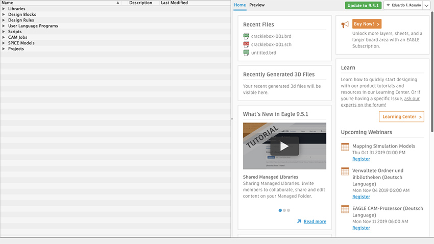
Figure 28 Eagle Control Panel
Libraries are a powerful feature of Eagle, and we’ll start by installing SparkFun and Adafruit libraries. These will come very handful, because these include standard stock parts from Sparkfun and Adafruit projects, such as audio and barrel jacks, potentiometers, common chips, and so on. All you need to do is explained on this step-by-step guide: www.autodesk.com/products/eagle/blog/library-basics-install-use-sparkfun-adafruit-libraries-autodesk-eagle/
Download the libraries from their Github repositories. If Github is new to you, then just click on Clone or Download and select Download ZIP. Create a folder in your Documents directory and copy/paste the extracted files there. Now go to Eagle’s control panel and on the Options tab, select Directories. The first path on the top is for the Libraries. Instead of having $HOME/Documents/EAGLE/libraries change the path for $HOME/Documents/eagle_external_lbrs and click OK.
Go to the Control Panel and under Libraries the “new external libraries” folder will show up, but these have not yet been activated. You’ll notice a gray dot is next to each item in the library. To activate the libraries, right click on the library folder, select “Use All”, and all those gray dots are now green. SparkFun and Adafruit parts are now available for use in Eagle. As your skills develop and projects grow in complexity, you can create your own custom libraries in Eagle.
Now move to the Projects folder at the bottom of the list of the control panel. When opened, two subfolders will show: “Projects” and “Examples”. If you are curious and have time, feel free to explore the Examples folder, where you will find many references on what Eagle can do. The user’s Projects folder will be empty.
Let’s create a new project. It’s good to start by making a new Project folder. Right click on your Projects folder, select New Folder and name it as you please. I will call mine HEM_PCBs. Now right click the new folder and select New Project. Name it however you want; mine will be called Synth4584-001. Notice that next to your Project there is a green dot, which indicates the currently active project. The dot for every other project will be gray and slightly smaller.
Schematic
Right click on your new Project, go to New and select Schematic (figure 29). (In Eagle you do your design work in schematic form, rather than on a virtual breadboard, as we did in Fritzing; this might make the process more difficult for beginners, but has the long-term advantage of making it easier to import circuit designs from the rest of the world). The Schematic Editor window will open (figure 30). In this editor you can work out the logical representation of your project. On the left is the toolbar with all the different commands. From the top downwards, you will see many other features, including a command line right before the white working surface. The little cross on that surface is the origin, point 0, 0. It is not moveable.
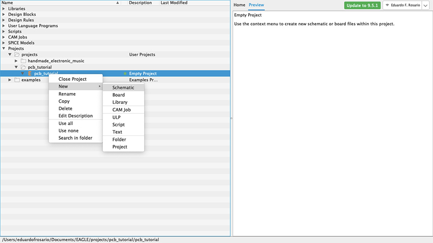
Figure 29 New Project window
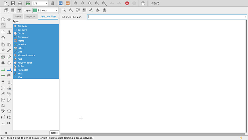
Figure 30 Schematic editor
On the top-left you will see a little grid (figure 31). Click on it and a new pop-up menu will open. Where it says Display, select On and then click OK (figure 32). Your working surface now looks like graph paper. This is very important because everything you do will snap to that grid even if the display is off. By default, the spacing of the grid is 0.1 inch and it is strongly recommended to use that default settings: everything in the schematic editor is spaced at tenths of an inch and, since everything snaps to the grid, you can confirm that each connection was made successfully. An even finer grid will be available if you press the alt key, but my advice is to limit its use only for graphics or notes but not for the actual schematic.
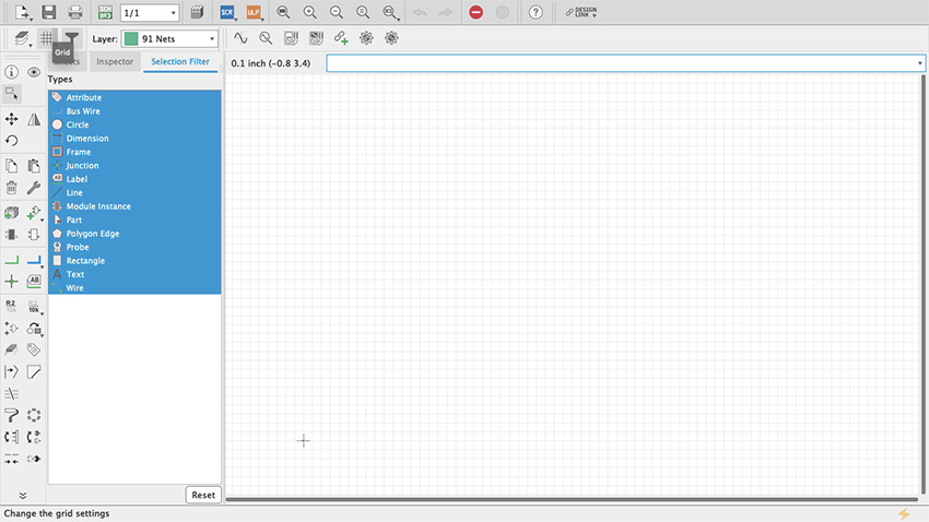
Figure 31 Grid
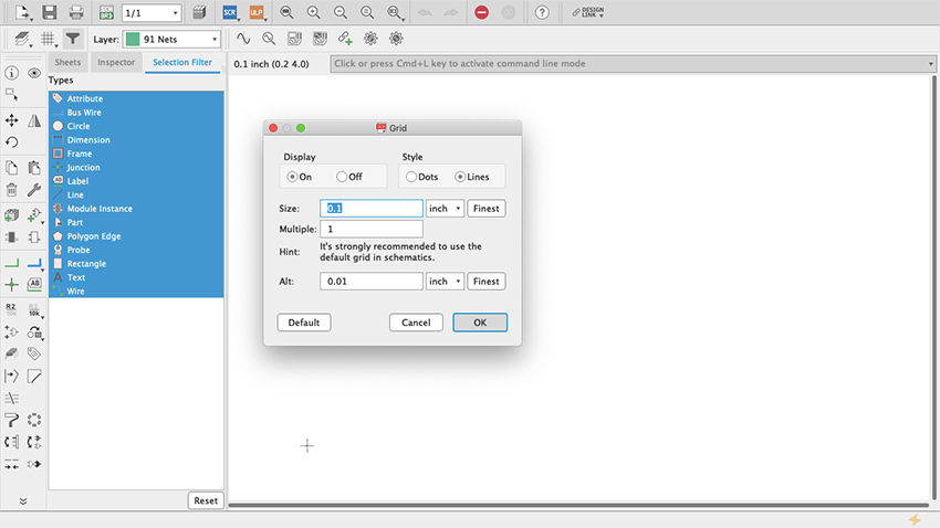
Figure 32 Display Grid
Let’s start putting things together. On the toolbar there is something that looks like an AC power plug with a green + symbol (my guess is that it is a symbol for an AND Gate) (figure 33). If you hover your cursor on top it will say “add part”. Click it. This is how you get access to all the parts libraries that come with Eagle. In here you will find pretty much everything you might need; if not, new libraries can be made and/or installed (as we did at the start of our Eagle tutorial) (figure 34). You access these through the Control Panel’s Libraries dropdown menu (figure 35). The important thing to know is that Eagle’s part library’s search bar cuts no slack to anybody: it will look for exactly what you type. This can be frustrating and can lead you to think that none of the parts that you need are available on Eagle. Because of that, Eagle allows the user to include wildcard characters as part of the search, including the question mark (?) and the asterisk (*). The question mark is for just one character and the asterisk for any number of characters. Sometimes, for example, integrated circuits come will all sort of prefixes and suffixes which are hard to remember. When you look for just the digits that you remember, nothing shows up even though it might be the standard name of the part. In that case wildcards can help.
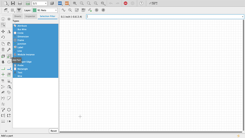
Figure 33 Add Part Command
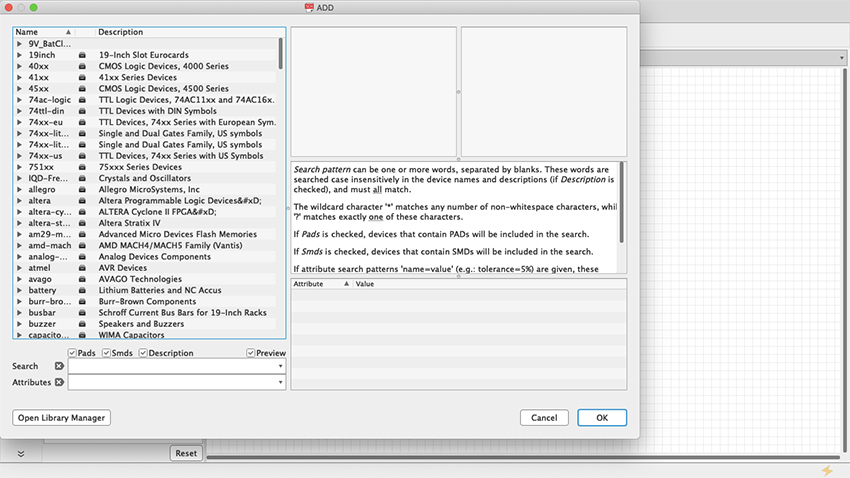
Figure 34 Add Part Menu
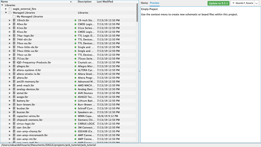
Figure 35 Libraries Control Panel
For our simple synth project, the first thing we need is the Hex Schmitt Trigger we used in our Fritzing tutorial. If you type 4584—which is one of the names the chip goes by—nothing will show up. It will say on the right “Sorry, no match!” (figure 36). But if you search for “4584?” the part will show up because there are two flavors of the same chip each with a different character at the end: D for small outline (SO) package and N for dual in-line (DIL) package (figure 37). Entering “Hex Schmitt Trigger” will reveal more than one part, “74C14” will have the same result as “4584?”, and searching “74*” or “45*” returns long lists (figure 38).
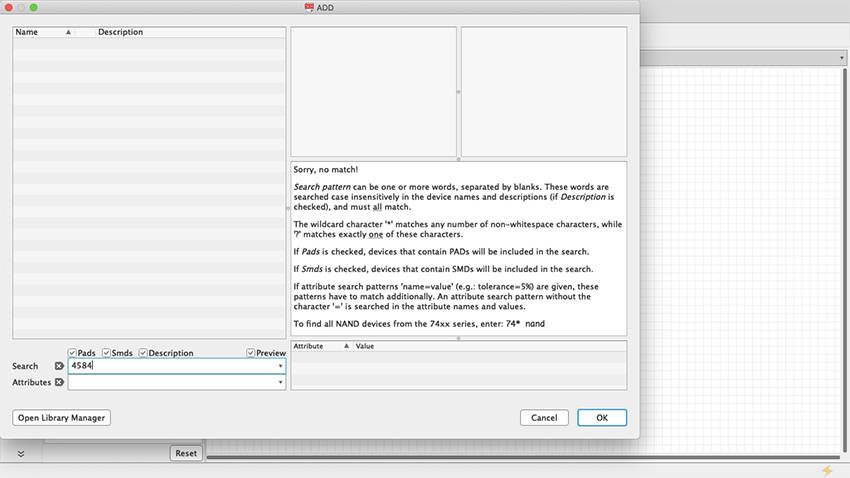
Figure 36 Sorry no match
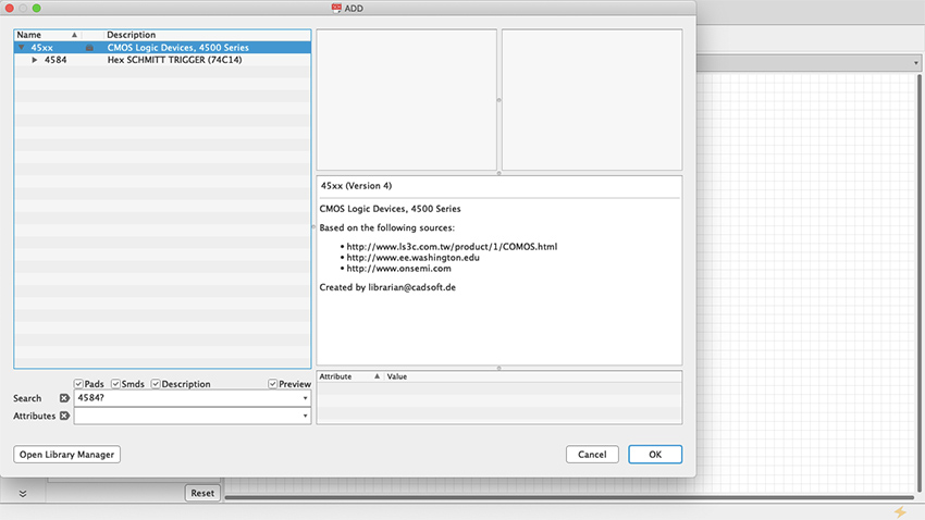
Figure 37 ? Wildcard
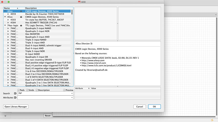
Figure 38 * Wildcard
The Hex Schmitt Trigger has six inverters on a single chip. When you select the part from the library it will give you the first inverter of the chip (Figure 39), but as you keep stamping the part across the schematic sheet, each iteration will consist of a new stage, respectively labeled IC1A, IC1B, IC1C and so on, until all six have been used up; stamp some more and Eagle will add a second chip, and you will see IC2A, IC2B, etc. (Figure 40).
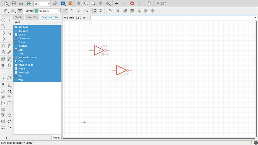
Figure 39 A single inverter
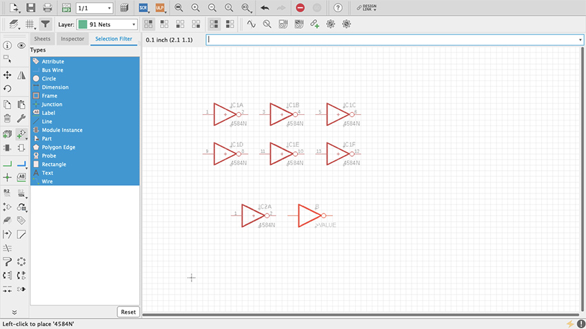
Figure 40 All inverters
Start by adding power and ground as we did with Fritzing. These will be found on the supply1 and supply2 libraries. Select VCC (+ V) and GND from either supply1 or supply2 (Figure 41, 42, 43). As long as they have the same name, power and ground busses are always connected and therefore do not need to be physically connected together in the schematic. Copying and pasting VCC and GND wherever necessary is enough. But, where and how do we connect them? As you have probably noticed already, the power and ground pins of the Hex Schmitt Trigger (7 and 14 respectively) are not available even after you have pasted all six inverter sections. We need to ask for them which we do by right clicking on the little cross at the center of the chip—that is the part origin—and selecting “Invoke” (Figure 44). A pop-up window will show a list, at the bottom of which you will see “P PMRN request 0” (Figure 45). Select it and click OK. Two new pins appear, which you can place on top of the part using the origin for reference (Figure 46, 47). By default, the top one will be + power and the bottom one ground. To make connections in the schematic editor, select in the toolbar a green L shaped symbol called Net (Figure 48). Once selected, whenever a connection can be made, a hollow green circle will appear when hovering the cursor. Arrange the parts as you see fit in the sheet and make the connections (Figure 40). Resistors, capacitors and inductors are found on a library called “rcl” (Figure 50, 51, 52). For power connect a 9v battery clip to the wire pads (Figure 53). Then add an audio jack (figure 54, 55, 56, 57, 58, 59).
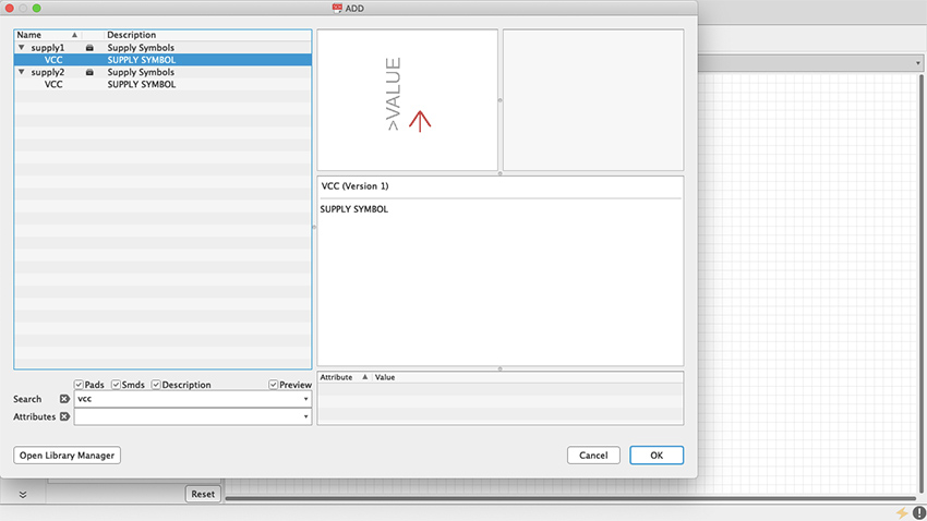
Figure 41 VCC
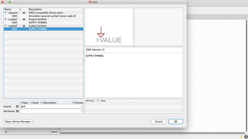
Figure 42 GND
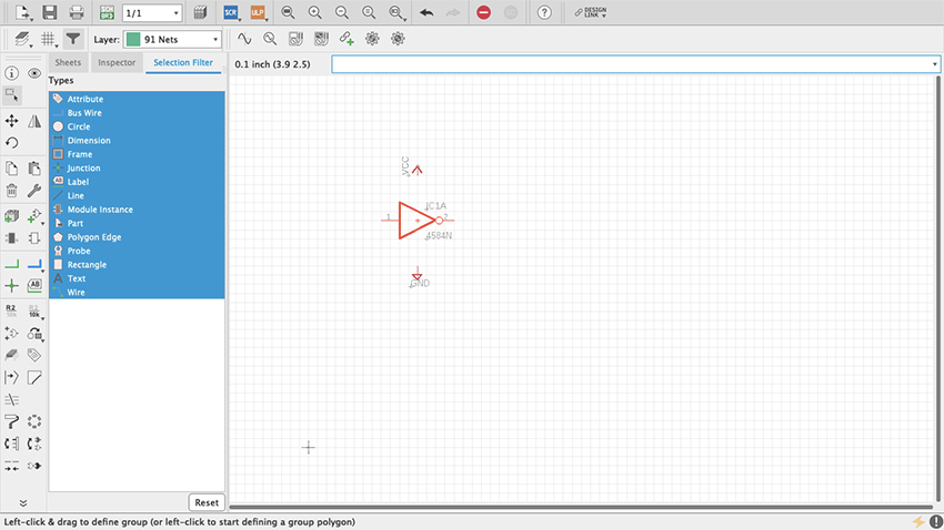
Figure 43 VCC & GND in Schematic
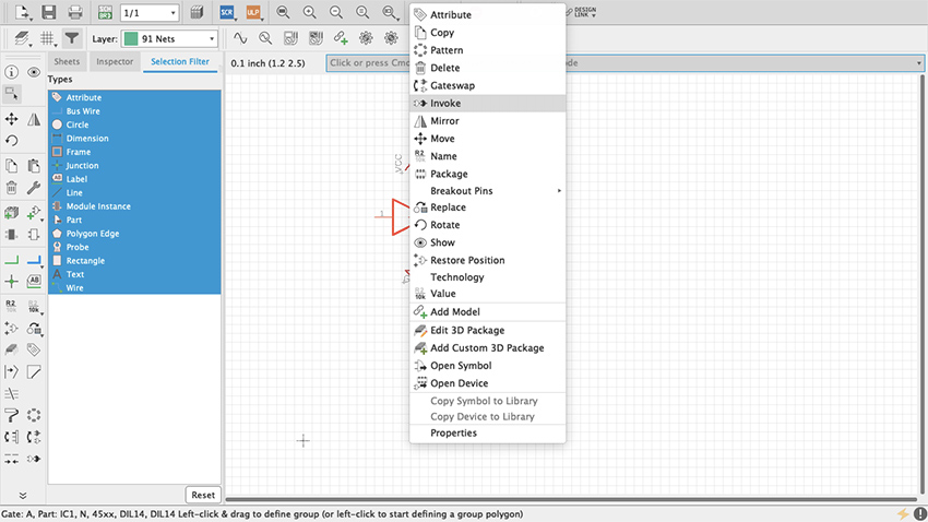
Figure 44 Invoke
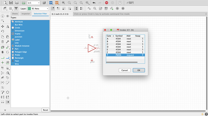
Figure 45 Invoke Box
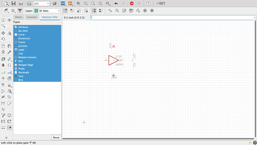
Figure 46 VCC & GND Pins
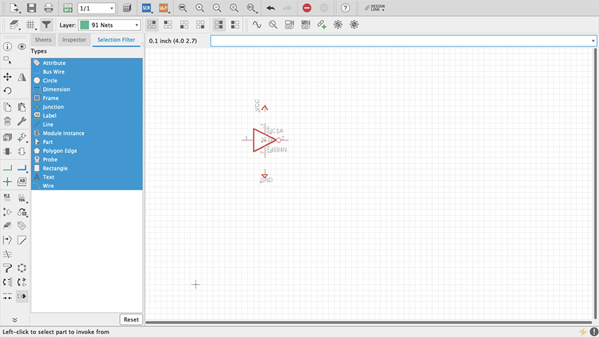
Figure 47 VCC & GND Pins
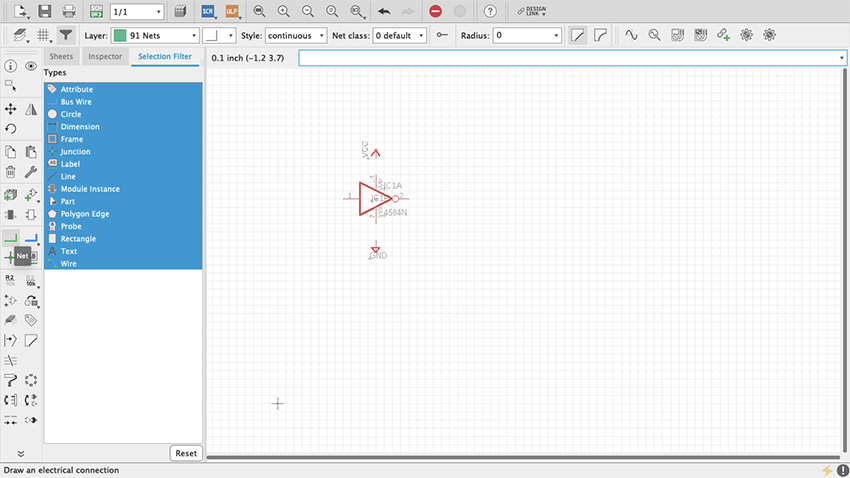
Figure 48 Net Command
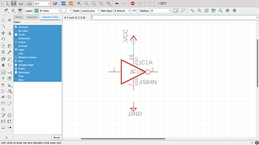
Figure 49 PWR Pins Connected
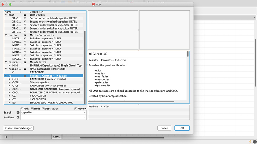
Figure 50 rcl library
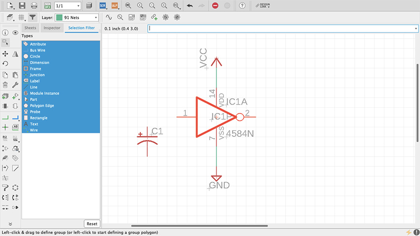
Figure 51 Capacitor
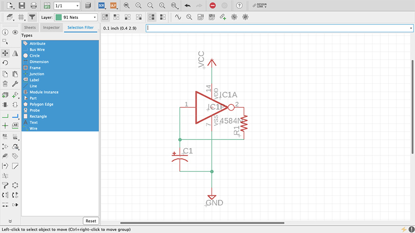
Figure 52 Resistor and Capacitor
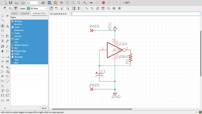
Figure 53 Wirepads
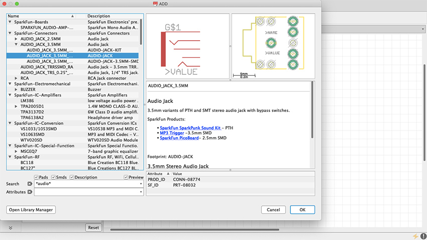
Figure 54 Audio Jack
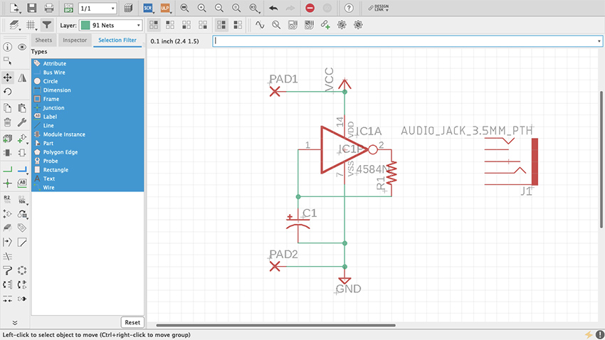
Figure 55 Audio Jack in Schematic
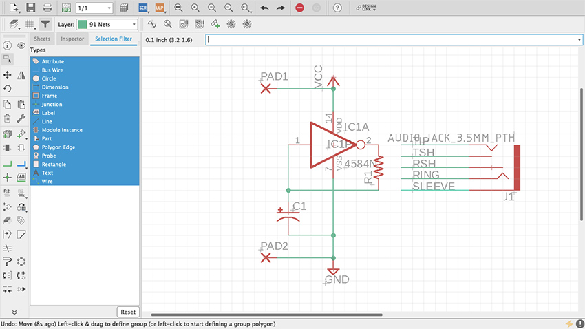
Figure 56 Audio Jack Pins
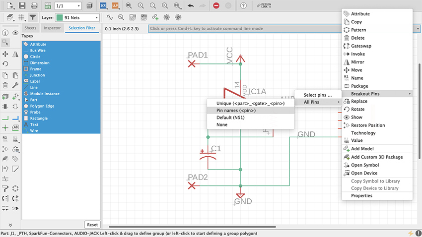
Figure 56.1 Audio Jack Pins
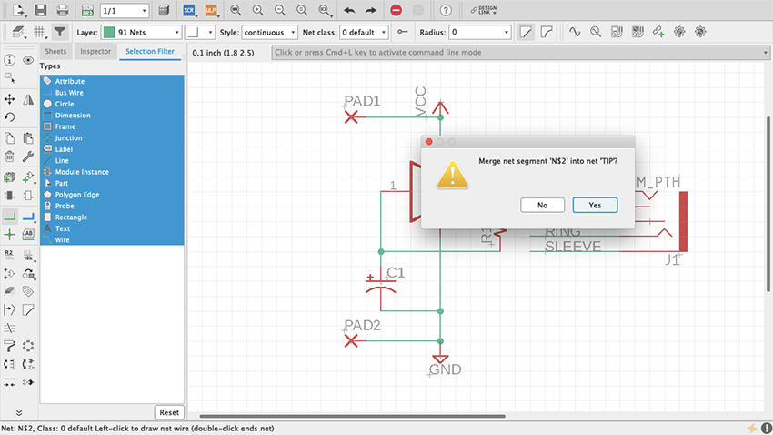
Figure 57 TIP-Audio Jack Pins
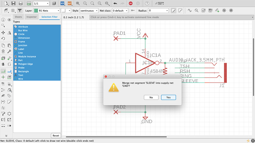
Figure 58 SLEEVE-Audio Jack Pins
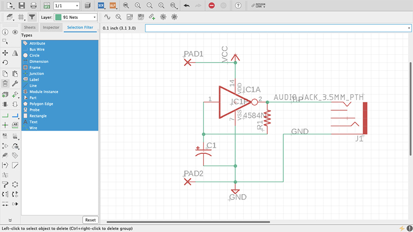
Figure 59 Audio Jack Connected
Board Layout
Now that the schematic is done, it’s time to work on the board layout. At the top of the editor, to the right of the Print icon, there is a gray and green square that reads SCH BRD. Click it. It will prompt a message saying that the board does not exist and ask whether it should be created (figure 60). Click “Yes” and the board layout editor will open. On this editor many new features are introduced. New items have been added to the toolbar on the left and others are no longer available. Next to it is the Design Manager (figure 61), which is a powerful tool that will help monitor and properly manage the board layout. If it is not there by default, open it through the View tab on top.
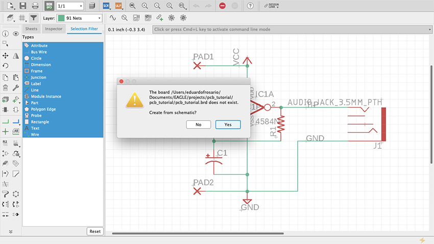
Figure 60 Create from Schematic
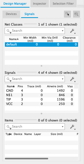
Figure 61 Design Manager
Unlike working with the schematic, in the board editor the grid can be changed as needed. It will default to twentieths of an inch, but any desired measurement can be used. Even though the pins of the integrated circuit we are using are spaced at a tenth of an inch from one another, the components that connect to them can be freely placed around it. Turn On the display and adjust the grid to your preference. Additionally, if you go Options > User Interface, you can change your cursor from Small to Large (figure. 61.1). This is optional but I think the larger cursor is useful for arranging parts on the board. (This feature is also available for the Schematic view.)
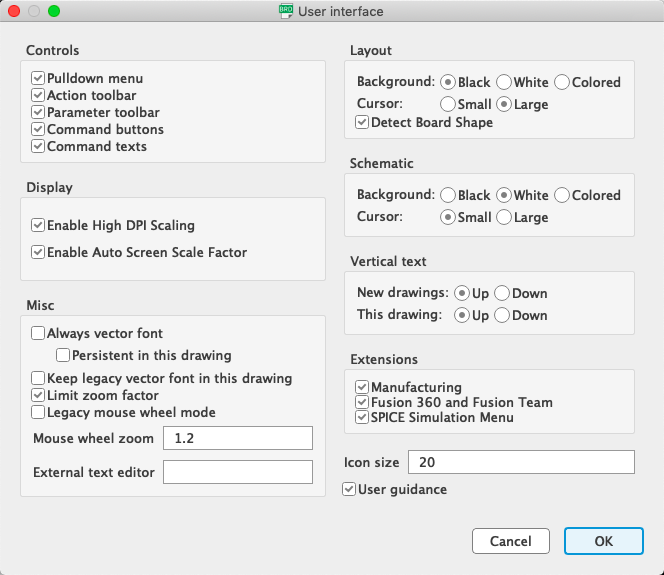
Figure 61.1 Cursor large
As mentioned before, both editors on Eagle are synchronized. Eagle keeps track of what happens in one editor and translates that into the other immediately. Closing one editor and working on the other will disturb that synchronization, and not only is the project’s health at a high risk but trying to undo changes is the thing of nightmares. That is why, when an editor is closed, Eagle will let you know that synchronization has been lost with a yellow and black warning ribbon (figure 62).
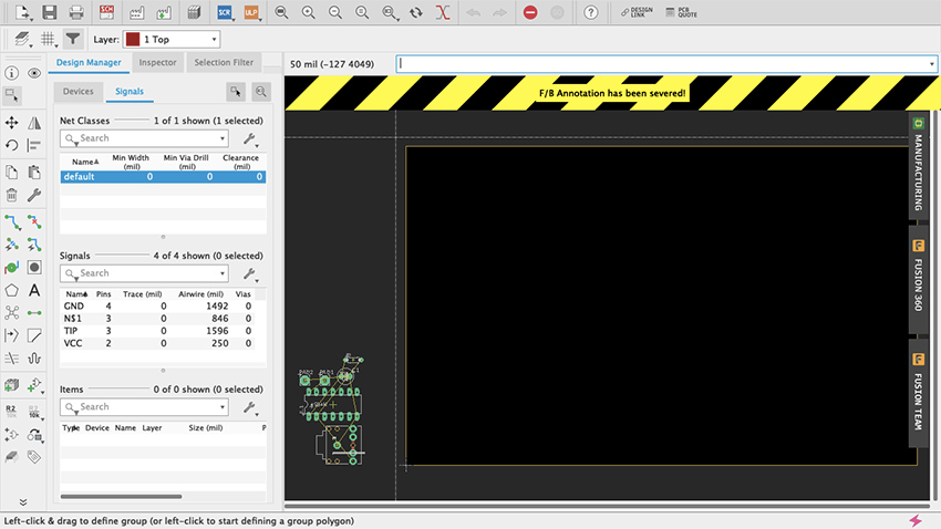
Figure 62 Sync warning
A very important part of both editors is the Layer Settings (figure 63, 64). When working in the board layout, this feature will acquire particular prominence as the different components are distributed across the board. Access to the Layer Settings is available through the toolbar by clicking on the stacked-up rectangles above the Move command. All layers will be listed on this menu. Visible ones will have an eye on the left. PCBs usually consist of a substrate (such as fiberglass) with copper, soldermask and silkscreen layers on each side. On Eagle, the Top copper layer is red and the Bottom copper layer is blue (unlike Fritzing which is yellow and orange respectively); Pads and Vias are green; Dimension, which is the board outline, is mustard yellow; and other layers such as the Drills are gray. You will probably memorize this as you work. If some work needed to be done on a particular set of layers, here is where they are managed.
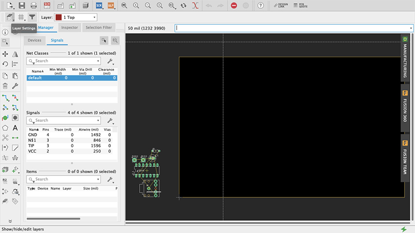
Figure 63 Layer Settings
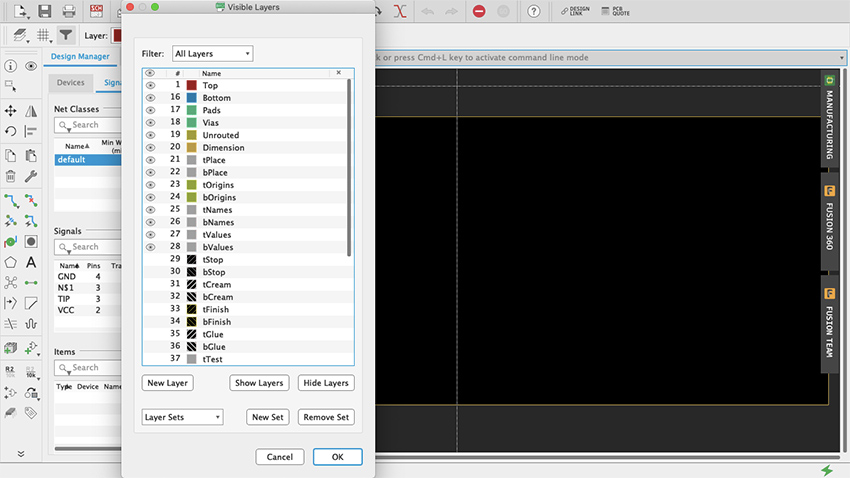
Figure 64 Layer Settings Menu
To keep things simple, we will design a single-sided board. This means that all parts will be placed on the top and all traces will be on the bottom (like when using a generic proto-board). Even though circuits done in this chapter are quite simple, you can do a double-sided board if you wanted to. But if you are milling the board yourself I would recommend sticking to single-sided for now (see “Milling PCBs” below).
All the parts of the design will be placed at the bottom-left of the workspace (figure 65). The black rectangle with yellow borders is the board. It can be modified as the design is being worked. Using the Group tool, move everything onto the board (figure 66, 67). There are yellow lines connecting the parts. These are not traces on the board but “airwires”, and they show how everything is connected. Start by arranging the parts however you please on the board. Use the airwires as a reference on how to distribute the parts. Clicking the Ratsnest button (figure 68) will recalculate airwires -- it looks like an X made with five circles and is located below the Polygon command (which looks like a pentagon). If airwires bother you, open the Layers menu and deselect the Unrouted layer. Start by placing the chip, which is the most complex part, and then add supply, resistors, capacitors, diodes and jumpers (figure 69).
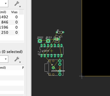
Figure 65 Parts at the bottom-left
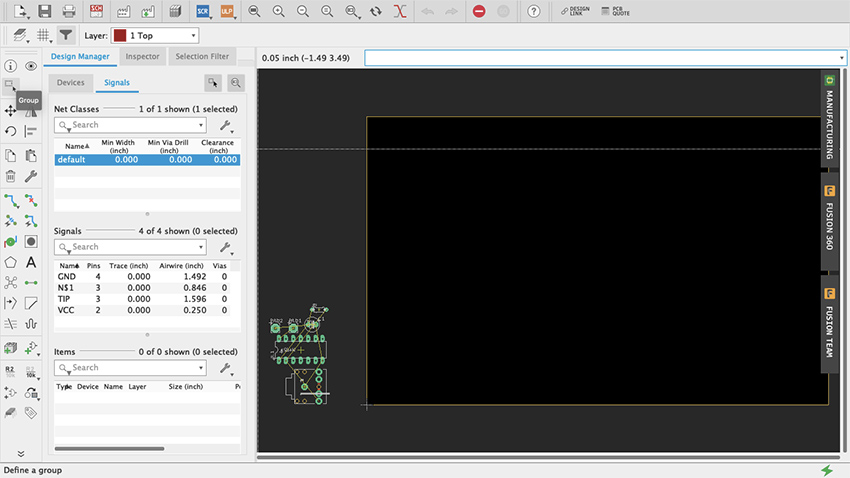
Figure 66 Group Tool
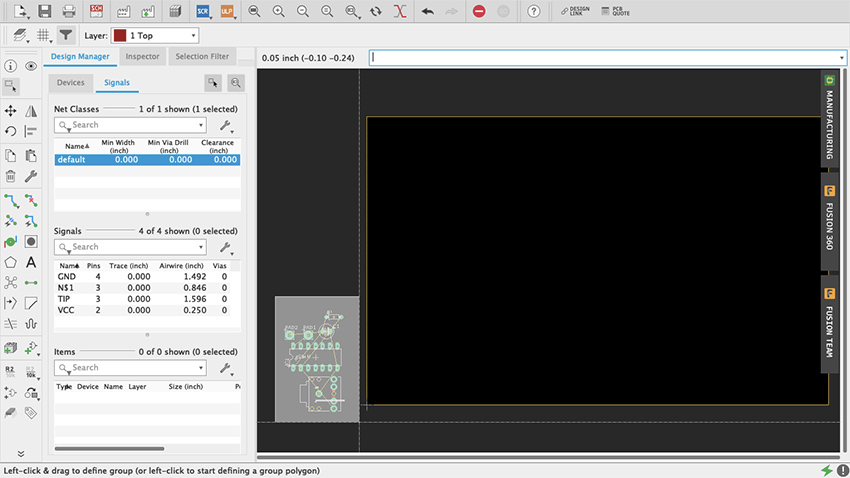
Figure 67 Group Tool Select
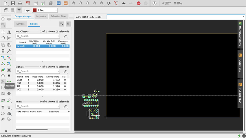
Figure 68 Ratsnest
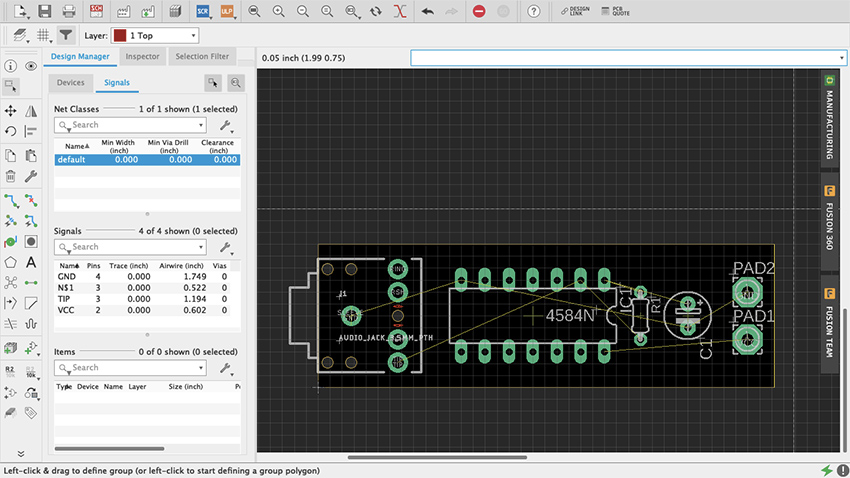
Figure 69 Parts arranged
To make the traces we use the Route command (figure 70). In the toolbar it is the one right below the Rotate command, represented by two green dots connected by a blue trace. An arrow pointing downwards on the Route icon accesses a few additional modes of this command (such as Quick Route Signal). Route Airwire should suffice for now, but if you are feeling curious try the other modes and see what they do. Above the workspace and the command line are additional important settings for this tool. Start by selecting “16 Bottom” on the Layer drop-down menu since we will be making a single-sided board with all the traces at the bottom. Right next to that are some routing behavior settings. “Walkaround Obstacles” will be selected by default and that is good. On the Width menu, since it is a simple circuit, you can go with nice thick traces—0.024 or 0.032 are good values. Thicker traces are preferred when milling your board since thin ones peel off easier. For a single-sided board don’t worry about Vias shape or Drill size. For double-sided boards, round shape and auto Diameter should be alright. Make sure that Drill size is at least c. 0.02; the default value is probably alright, but I would recommend checking the board house specs (more on this later). For the Wire Bend, experiment as you go.
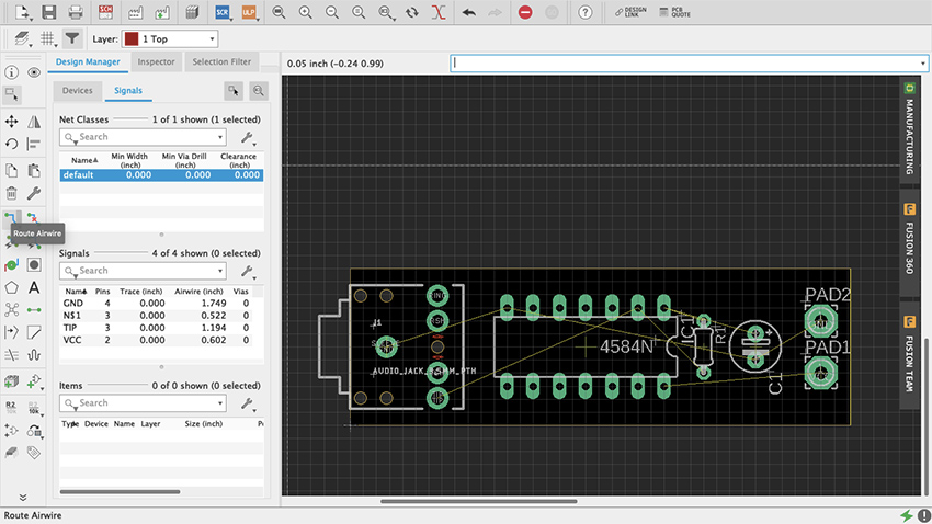
Figure 70 Route
To route a trace just click at one end of an airwire and complete the connection to the other end (figure 71, 71.1). As traces are being made the Route command will make suggestions on how to proceed. Clicking along the way creates fixed joints around which the traces will pivot. Once a trace is finished Eagle will make a sound and the name of the signal will be assigned to it. Vias allows you to move a signal from one side of a double-sided board to the other: simply press down your mouse’s scroll wheel or middle button, or manually change the layer and for the next trace a Vias will be on your cursor. To delete a trace just use the Ripup command (figure 72), to the right of Route on the toolbar, with a little red X. Play with the Route tool. Try different trace widths, try drawing shapes, see what kind of narratives can be told, explore how different arrangements of parts and traces affect the overall functionality of your design.
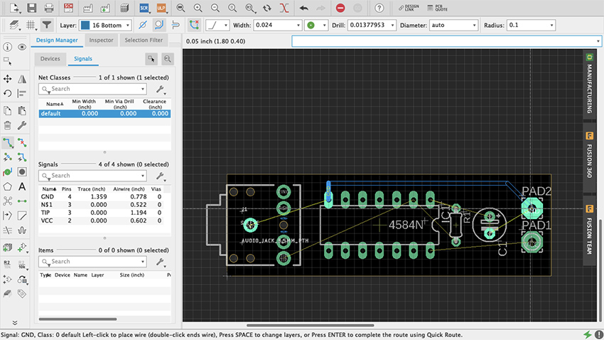
Figure 71 Making traces
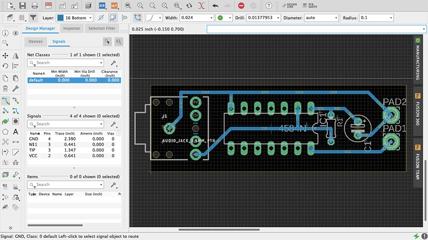
Figure 71.1 All traces
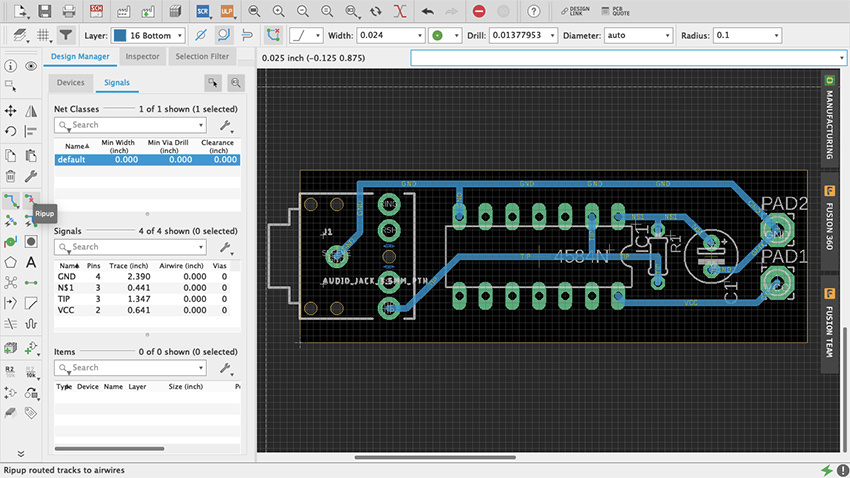
Figure 72 Ripup
Another way to proceed is using the Autorouter. In the Toolbar it looks like the Route command but with a little lightning bolt. Do not think of this as an easy way out but as a different approach to problem solving. Similar to Fritzing, it is highly unlikely that the solution that the Autorouter will come up with will be the best option – lots of editing afterwards. When selected it will prompt a Setup menu (figure 73). Try the default settings (if it is a single-sided board leave just the Bottom in Auto and select N/A for the Top) and press Continue. A Routing Variants window will appear, press Start. Once it is done, select one of the alternatives it came up with and press End Job. Now patiently edit the traces to fit your design’s needs.
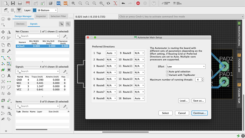
Figure 73 Autorouter
Fortunately, when routing one trace at a time, or editing the Autorouter’s traces, there is a way to make sure everything is correct: the Design Rule Check (figure 74). You will find it either under the Tools tab in the menu bar as DRC, or in the Toolbar when expanded using the double arrow at the bottom. The DRC will let you know whether your design meets specific manufacturing requirements. When opened, a setup window will appear with multiple tabs, each storing the default values for various important aspects of your design, such as the minimum distance between objects, minimum drills and width, etc. After you are done making traces go ahead and do a check with the default values. If there are any issues a DRC Errors pop-up window will appear (figure 75). For example, if some connection has been left unrouted, it will appear as an Airwire under Errors. If you select a specific error in the menu, Eagle will indicate where it is in your Board Layout. If there are no errors (wheee!) you will see in the bottom left corner a message that reads “DRC: No errors.” You can also load third party design rules with .dru files.
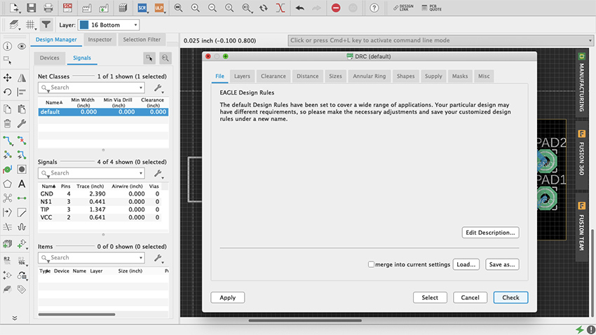
Figure 74 DRC
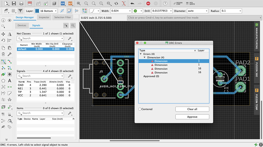
Figure 75 DRC Error
It is common practice to do a “copper pour” at some point when doing your board layout. A copper pour is when an “open” part of the board is filled with copper and connections are made to it. The most common use is as a ground plane, which reduces noise in circuits. Some do it at the beginning to simplify what could otherwise be a complex design to route, and others do it at the end as nice finishing touch with practical benefits. It is not obligatory, yet it does not hurt to do so, therefore it is up to you. Copper pour in Eagle are easy. Select the Polygon tool (figure 76) and draw your board’s outline on the desired layer, either Top or Bottom (figure 77). Once you have completed the shape, a dialog box will ask you to enter the signal’s name, which is usually ground, named GND or something similar (figure 78). If you are not sure, check with the Design Manager. Once you have entered the signal the polygon’s outline will be dashed (figure 79). If it never asked for a final name to be entered, use the Name command that’s between the Design Block and Copy commands, as “R2 /10k” (hover your cursor on top of it and it should say “Name”) (figure 80). Click the polygon outline, enter the name and select the “this Polygon” option (figure 81). To finish select the Ratsnest command and copper should cover the entirety of the “open” board surface, avoiding all traces other than GND (figure 82). All GND traces now connect to this plane and every other path should have the minimum clearance from it. Depending of what your design is, doing ground pours can be essential for things such as decoupling. But there is occasionally great joy in making circuits misbehave, so it is up to you how you use it.
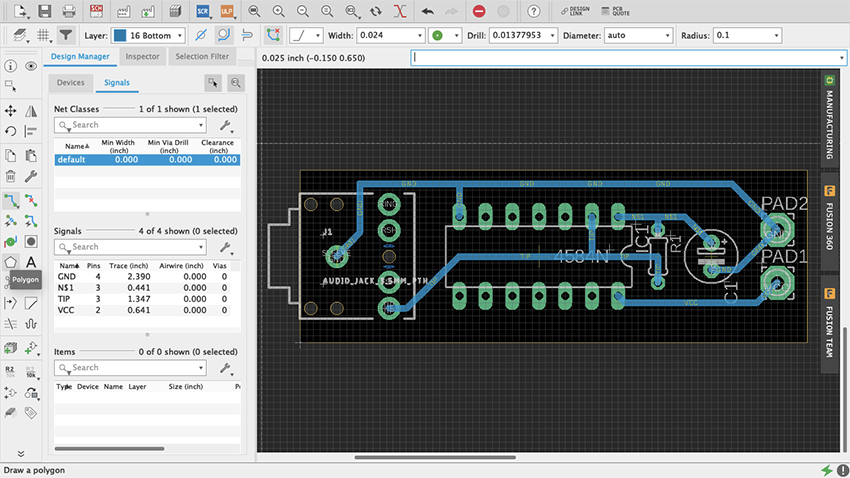
Figure 76 Polygon Tool
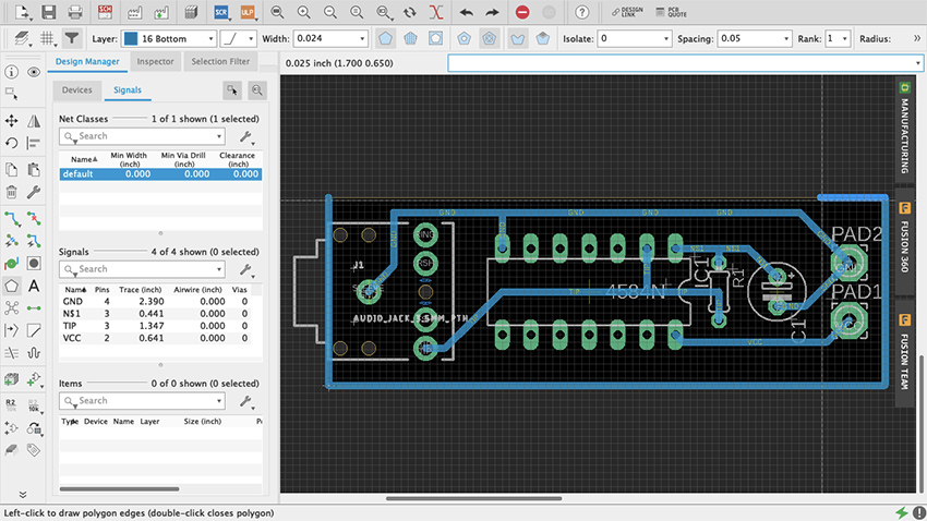
Figure 77 Polygon
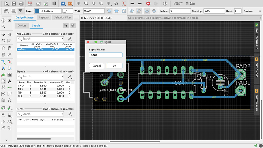
Figure 78 Signal Name Polygon
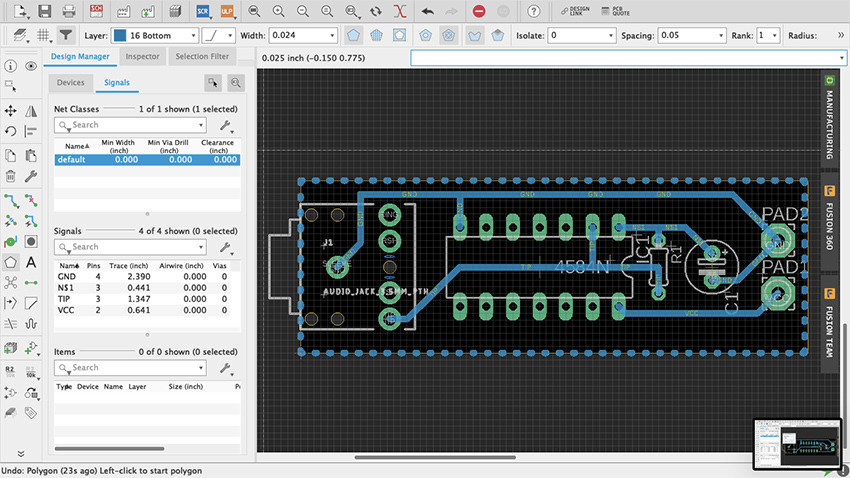
Figure 79 Dashed Polygon
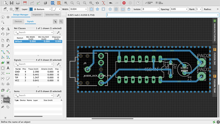
Figure 80 Name Command
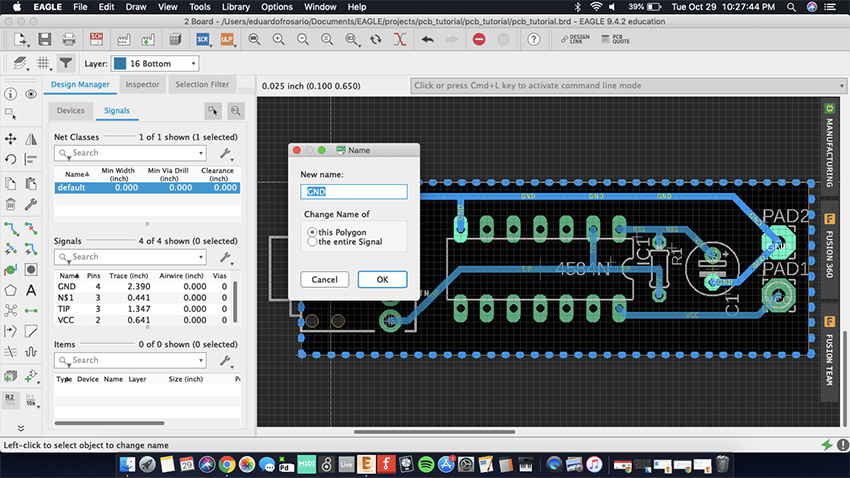
Figure 81 This Polygon
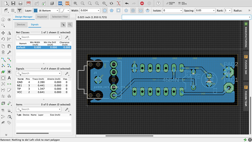
Figure 82 Copper Pour
Making boards
It’s good practice to print your board layout on paper once it is done, glue it on a styrofoam block, and do a mock-up version of the circuit to make sure that the parts are correct and that the spacings are adequate (thank you Robert Drinkwater!). It is no fun to find yourself fixing every hole on the board with a pin vise because they were too small; or learning that the legs of your switch do not match the part that was used as a template for the design. If everything fits alright on paper, then we can fabricate a prototype.
There are three option when it comes to making your own boards: etching, milling and manufacture. Etching will not be covered on this chapter – despite its old-school cred (think Robert Moog’s 1950s Theremin kits) -- because improperly disposed ferric oxide will not only ruin your sink and plumbing, but is also a serious environmental hazard and is illegal to throw out. The other two approaches are safer.
Milling PCBs
Milling boards is a fast and reliable way of prototyping your designs before manufacturing them by the hundreds through a commercial house. It can be sufficient to produce a handful of boards for yourself and your friends. For this example, I will focus on Bantam Tools Desktop PCB Milling Machine, a CNC machine. Although at the time of writing still a little pricey for the amateur hacker, they are popping up in art schools and maker spaces. Ask around, but if for any reason milling is not an option, jump ahead to the next section on board houses.
The first thing to do is download Bantam’s milling machine software to communicate with the mill and setup your project. You find it at bantamtools.com/software-download. Install the application and launch it. The software is simple and fairly intuitive. In the center of your computer screen you should see the bed of the machine and a blue block, which is your generic material (figure 83). Zooming out enough will reveal an opaque image of the mill (figure 84). Above, different views are available: front, top and 3D; as well as preview and toolpath options. On the right are the configuration settings for your project. Connect the mill to your computer. Locate the bed.
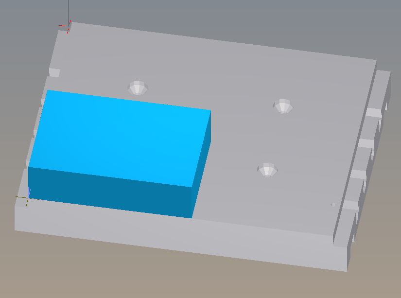
Figure 83 Bantam Material
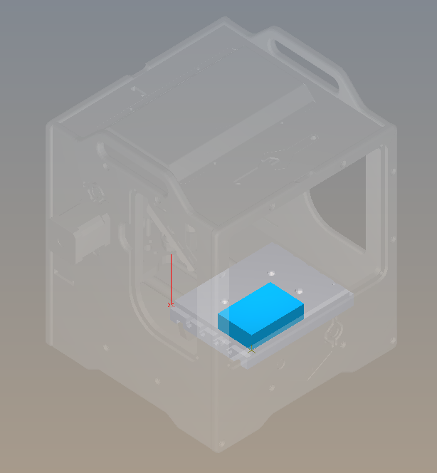
Figure 84 Bantam Machine
Printed circuit boards are made of different materials. FR-4, made of fiberglass and epoxy resin, is probably the most common, but because of the fiberglass, machining FR-4 is dangerous for your health. Instead we are going to use FR-1, made with phenolic resin, which is safer (but nonetheless avoid ingesting, inhaling or getting it in your eyes). FR-1 can be acquired from many sources, including Bantam but also SparkFun and Digi-Key. On Bantam’s Material dropdown menu select Single-Sided FR-1. On the Material dropdown menu select Single-Sided FR1. Immediately the generic blue block turns into a copper board. If the board you have has different measurements, adjust the width and the height on the Size menu. I recommend leaving the default value thickness. Using thin double-sided tape, place your board on the mill’s bed and against the guides. The tape is just so that the board is stable while the machines works. Do no use anything thicker than scotch tape.
Import your design from your EDA (Fritzing, Eagle, etc.) into Bantam by clicking on the open button on the Plans section. Bantam supports many different file formats but we will use “.brd.” The design layout will appear on the board and can be moved within the boundaries. Use the placement menu to indicate the location and orientation. Leave small distance between the design and the guides for the safety of the drill bit.
In Milling Tools select the sizes of the bits that you will be using. If two traces are too close for the bit diameter, red marks will show on the design. You can try different milling tools, or the traces can be adjusted in Eagle and refreshed on Bantam so that the changes are reflected. Whenever possible use just one tool for the whole job, it’s easier. Below the Start Milling button is an estimate of how much time will it take to mill the board. Under Advance, both the depth and clearance of the traces can be adjusted. Remember that milling too deep may result in a fragile board and also the bit will become dull faster. Too much clearance will increase the turnaround time considerably, and also will make the bit dull faster.
Once your setup is ready click Mill All Visible. The machine will ask for you to insert the new tool. After tool is in place the mill “locates” the tool by touching the bed. Then milling starts.
When the board is ready, carefully—you don’t want to snap it—lift it off the bed. Before soldering the components in place, take the time to check and clean the board. Make sure that there is no copper residue shorting the circuit.
Assemble the board carefully. FR1 boards will allow for maybe one soldering mistake before the copper burns or peels off.
Manufacturing
Getting a board design manufactured requires that the files are submitted that comply with the board house’s specifications. There are hundreds of manufacturers, and although the process is fairly standardized, requirements often differ from one to another. Failing to adhere to the appropriate spec may result in mistakes, or the board not being produced at all. Eagle makes it very easy to generate the necessary manufacturing files. These are Gerber (.gbr) files which include copper, soldermask and silkscreen, among other layers; and Excellon (.xln) for your drill files.
Some manufacturers, such as OSH Park, accept Eagle’s .brd files so you don’t need to generate additional files. Nonetheless, you should import their Design Rule files and check your design. Go to docs.oshpark.com/design-tools/eagle/design-rules-files/ and download the .dru file for either 2 or 4-layer boards. Then, on Eagle, go to Tools > DRC > Load and select the .dru file that you just downloaded for your project. Now when you do a Design Rules Check, Eagle will use OSH Park’s specifications.
You might work with various board houses, so knowing how to produce the necessary files is important. First, open up the CAM processor, which is at the top on the board editor and looks like a factory with three windows (figure 85). CAM stands for computer-aided manufacturing. This new menu is divided into a few different parts (figure 86). On the upper-left corner a bar will tell what kind of CAM job will be produced. The default for our version of Eagle is a 2-layer template. If you click on the paper sheet icon next to it, a drop-down menu will offer additional options (figure 87).
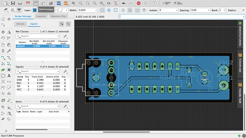
Figure 85 Eagle CAM Processor
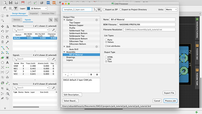
Figure 86 Menu CAM Processor
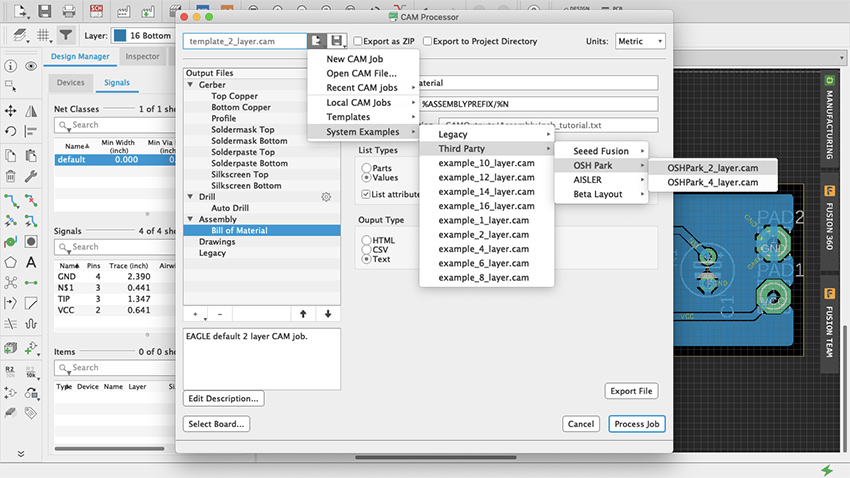
Figure 87 CAM Job Templates
On the left the Output Files section lists all the different types of files and their contents. For example, when one of the Gerber files is selected, its contents will be made visible as a list in the Layers panel, along with a graphic representation of those layers (figure 88). Two check-boxes for board shape and cutouts are available to include on each of the files. These can prove useful for aligning and assembly, but check with your board house specs if it is necessary to do so.
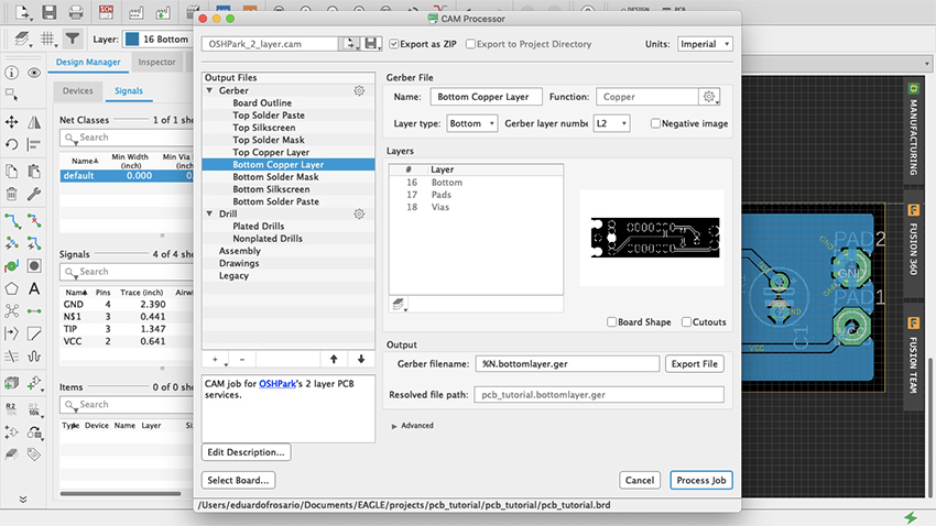
Figure 88 Output Files
Before exporting anything click on “Gerber” in the Output Files section, and on Options the default should be either Gerber RS-274X or the newer format Gerber X2. Gerber X2 is backwards compatible and will work with any board manufacturer. All files will be exported when Process Job is clicked. Individual files can be obtained by using the Output bar below the Layers section: select the layer you want and click Export File.
A good way to start production is to use the third-party CAM job files included with Eagle. Press Load Job File—which is the paper sheet icon with an arrow pointing to the right—then at the bottom select System Examples > Third Party and in there you will find Seeed, OSH Park, Aisler and Beta Layout CAM job files for 2, 4 and even 6-layer boards. All these manufacturers offer professional PCB services for reasonable prices and a prompt turnaround. There is no need to produce 100 boards of a design that has not been tested out. An order can be placed with OSH Park—for example—for as little as 3 boards. This way economic risk—and e-waste—is reduced significantly when a project is still in its development phase. Eagle is not the only EDA that offers CAM templates. Fritzing is also affiliated with Aisler, or you can ask your board house of preference whether they have .dru file and/or CAM Job templates. There are manufacturers all over the world and there is no need to stick to these specifically. If another PCB manufacturer is particularly convenient because of location or any other reason, contact them and request their specifications. Once everything’s setup the way you want it on the CAM Processor, click Process Job (figure 89, 90) and all the files will be saved in a .zip file ready to be sent to the board house.
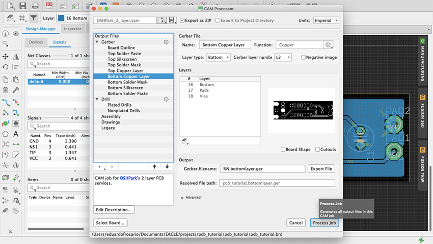
Figure 89 Process Job
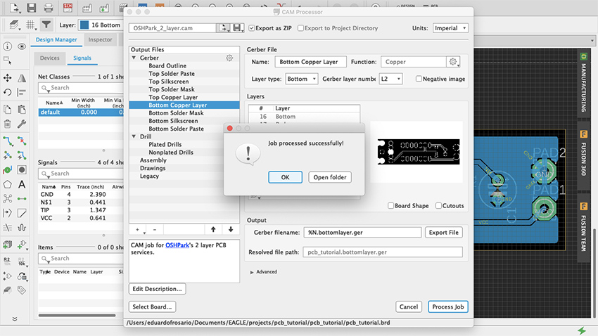
Figure 90 CAM Job Successful
Going forward, a good thing to explore is how to make new parts in Eagle. This is not difficult. You can start by duplicating and modifying an already existing part to suit your needs. Parts are made of a symbol and a package, they meet to form a device that lives in your parts library. You can find many step-by-step guides with a quick search online. Understanding how parts are made can shed some additional light on the best way to develop your designs, and which parts to choose from the vast libraries. Unlike Fritzing, Eagle doesn’t have a Breadboard view. But because there are 3D models of many of the parts in the library, a design can be imported into Fusion 360 to do further work on it.
Microcontroller Sound (Joseph Kramer)
Data files for chapter 33
Download Arduino (ZIP 113KB) Download Fritzing (ZIP 198KB)
Microcontroller Sound (Joseph Kramer): Additional projects
Circuit Two: Pseudo-analog effects, tones without delay, and notes quantized to scales.
Overview
The following circuit expands on the digital oscillators described in the book by adding a second knob and a volume control (via a light-dependent resistor paired with an LED). By controlling the brightness of the LED using pulse width modulation (PWM), intermediate volume levels can be achieved. The basic principle is explored in the first sketch, then expanded in the second sketch using the tone() function. Arrays are introduced in the third sketch, allowing for the playback of pre-programmed melodies with dynamic volumes. Finally, a simple quantizer is created to constrain notes performed via knob turns to desired scales.
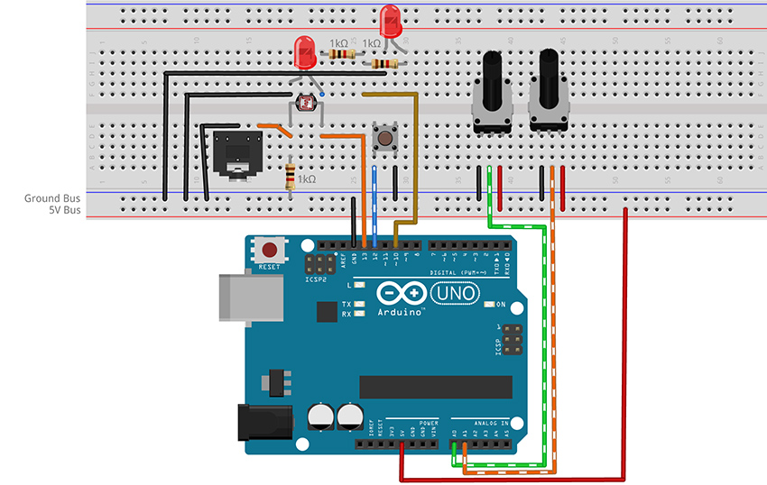
Figure 3 - Fritzing breadboard image of digital oscillator with volume control circuit
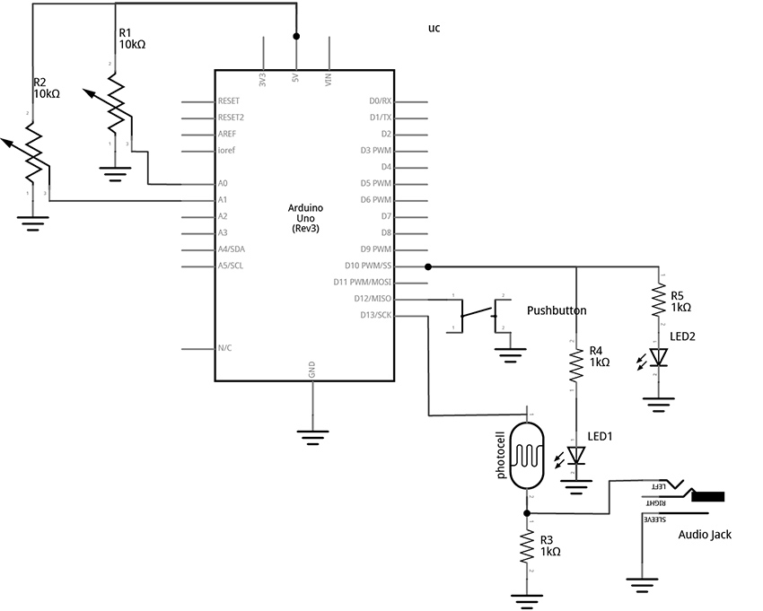
Figure 4 – Fritzing schematic of digital oscillator with volume control circuit
You will need:
- An Arduino Uno.
- A computer running the Arduino IDE software.
- A USB cable that can connect from your computer to the Uno’s USB type-B connector.
- A breadboard.
- Some solid hookup wire or premade wire jumpers.
- Assorted resistors (1kΩ – 100kΩ is a good range).
- A 10kΩ linear potentiometer.
- A pushbutton or toggle switch.
- Some photoresistors.
- Some LEDs (Light Emitting Diodes).
- An audio amplifier.
- Assorted jacks and plugs, to match your amplifier.
- Hand tools.
Connect the Hardware
- Open Fritzing File and navigate to Breadboard view
- Insert all components into breadboard matching the image
- Connect all wires on breadboard
- Connect wires from Arduino to breadboard
- Visually double-check all connections and wiring
- Connect the Arduino Uno to your Computer
Project One: Volume Control
Program the Arduino with the VolumeOSC sketch.
- Open the Arduino sketch
- Click the upload button near the top left of the sketch window
//CODE HEM_VolumeOSC ******

								int tonePin = 13;      //create a variable to represent LED Pin

								int buttonPin = 12;   //add variable for the button pin

								int volLED = 10;      //add variable for the Volume LED

								int periodKnob = A0;  //add variable for knob pin (A = analog in)

								int volumeKnob = A1;  //add variable for knob pin (A = analog in)

								int delayTime;        //create a variable for the delay time

								int fadeVal = 0;      //create a variable to store the brightness of the LED
								void setup() {

								  pinMode(tonePin, OUTPUT); //configure pin 13 as an output

								  //INPUT_PULLUP sets the pin high. It gets pulled "low" by

								  //connecting it to ground through a button

								  pinMode(buttonPin, INPUT_PULLUP);

								}
								void loop() {

								  //set delay time equal to the current value read on analog pin 0

								  delayTime = analogRead(periodKnob);


								  //map the analog read range from 0 - 1023 to 10000 to 1

								  delayTime = map(delayTime, 0, 1023, 10000, 1);


								  digitalWrite(tonePin, HIGH);

								  delayMicroseconds(delayTime);

								  digitalWrite(tonePin, LOW);

								  delayMicroseconds(delayTime);

								//check the button. It will be LOW if pressed

								  //If the button is pressed, write fade value to the LED:

								  if (digitalRead(buttonPin) == LOW) {

								    //read the fade knob and scale the range from

								    //10bits (0 - 1023) to 8 bits (0 - 255)

								    //analogRead is 10 bits

								    //analogWrite is 8 bits

								    //1023 divided by 4 is 255 (faster than map())

								    fadeVal = analogRead(volumeKnob) / 4;

								    analogWrite(volLED, fadeVal);

								  }
								else {

								    //turn LED off if button not pressed

								    analogWrite(volLED, 0);

								  }
								}

								//**********END OF CODE
What's Happening?
This sketch provides a method for creating analog-like effects using a technique called Pulse Width Modulation (PWM). This is done with the analogWrite() function, but is (confusingly) only possible on the digital pins. This is because, technically, PWM is still a digital signal. PWM works by toggling a pin high and low at a fixed frequency while adjusting the percentage of time that the wave is HIGH versus the time it is LOW in order to deliver less current than if the pin were just held at a constant HIGH level. This allows the LED to be set to intermediate levels of brightness between all the way ON (analogWrite(pin, 255) - PWM signal is HIGH 100% of the time), to a medium brightness (analogWrite(pin, 128) - PWM signal is HIGH 50% of the time), to all the way off (anlaogWrite(pin, 0) - PWM signal is HIGH 0% of the time). Take note that not all of the digital pins can generate PWM. Only the six pins with the tilde (~) symbol next to them are capable of this function.
We are using PWM to control the brightness of two LEDs from one pin. One of the LEDs is used for visual feedback, while the other is paired with a photocell with the intent to control volume with light. The benefit of using PWM is that in addition to simple binary blinking, we are able to program the brightness level smoothly from fully bright to completely dark. When using this technique to control volume the effect can imperfect (you may hear some of the PWM frequency in your signal – this can be improved by using a different microcontroller with a higher PWM frequency), but with some finessing of the led-photocell pairings the technique opens up fruitful avenues of experimentation.
This sketch uses a button and two knobs to control the activation, pitch, and loudness of an oscillator. The knob on pin A0 controls the pitch by setting the period of the waveform via the delayMicroseconds() argument. (This method of sound generation is described in an earlier project.) When the button is pressed, the knob connected to pin A1 sets the brightness of the LED in the photocell/LED pair. This brightness controls the volume of the oscillator via the voltage divider created by the photocell and fixed resistor pairing. When the button is released, the LED turns off and the note fades out at the photocell’s response speed. You may need to experiment with the value of the fixed resistor (1kΩ in the example) to get the best response from your photocell. (It may be useful to start with a potentiometer in place of the 1kΩ fixed resistor to dial in the value that works best for your photocell/LED pair. The technique for using a potentiometer to determine the value of a fixed resistor is described in the book.)
If your photocell causes a fade out due to a slow response time then you are likely to notice that the pitch of the oscillator changes when the button is released. This happens because the tone is generated by pausing at points in the loop using delays. But delays are not the only things that the microcontroller has to do, and each instruction adds time between toggles. This means the frequency can be affected by how long it takes for the microcontroller to get through the other instructions in the loop. When the button is pressed, the if statement is engaged and more lines of code have to be executed by the microcontroller compared to when the button is not pressed. As a result, there is more time between the pin going LOW and the pin going HIGH again. This lowers the pitch of the microcontroller slightly when the button is down. One approach to stabilizing the frequency is to make sure that the if statement and the else statement take the same amount of time by moving some instructions out of that structure and into the main loop. But a better way to handle this issue would be to do away with thedelay() method of tone generation altogether and instead make use the tone() function built into the Arduino library.
Project Two: Volume Control with Improved Timing via tone()
Program the Arduino with the VolumeOSC_tone sketch.
- Open the Arduino sketch
- Click the upload button near the top left of the sketch window
//CODE HEM_VolumeOSC_tone ******

								int tonePin = 13;           //create a variable to represent LED Pin

								int buttonPin = 12;       //add variable for the button pin

								int volLED = 10;       //add variable for the Volume LED

								int periodKnob = A0;  //add variable for knob pin (A = analog in)

								int volumeKnob = A1;  //add variable for knob pin (A = analog in)

								int knobVal;               //create a variable for the delay time

								int fadeVal = 0;           //create a variable to store the brightness of the LED
								void setup() {

								  pinMode(tonePin, OUTPUT); //configure pin 13 as an output

								  //INPUT_PULLUP sets the pin high. It gets pulled "low" by

								  //connecting it to ground through a button

								  pinMode(buttonPin, INPUT_PULLUP);

								}
								void loop() {

								  //set variable knobVal equal to the current value read on analog pin 0

								  knobVal = analogRead(periodKnob);
								//map the frequency range from 0 - 1023 to 110 - 1760

								  int toneFreq = map(knobVal, 0, 1023, 110, 1760);
								tone(tonePin, toneFreq);
								//check the button. It will be LOW if pressed

								  //If the button is pressed, fade up the LED:

								  if (digitalRead(buttonPin) == LOW) {

								    //read the fade knob and scale the range from

								    //10bits (0 - 1023) to 8 bits (0 - 255)

								    //analogRead is 10 bits

								    //analogWrite is 8 bits

								    //1023 divided by 4 is 255 (faster than map())

								    fadeVal = analogRead(volumeKnob) / 4;

								    analogWrite(volLED, fadeVal);

								  }
								else {

								    //do nothing if button

								    analogWrite(volLED, 0);

								  }
								}

								//**********END OF CODE
What's Happening?
Using the tone() function eliminates the need to employ the delay() function for our audio task. This has the benefit of freeing our loop to do other things without interference. To start a note using tone() we will call the function and pass it two arguments: which pin, and what frequency. If we want stop the tone, we can call the complementary function noTone() which will take one argument to clarify which pin to silence. The tone() function can produce frequencies from about 31Hz to nearly 5kHz. The map() function is used here to select a range from 110Hz to 1760Hz. These numbers were chosen by ear and can be adjusted to taste. For more ways to use tone() see the built-in examples at File>Examples>Digital>[…].
Keeping the audio generation free of delays frees us to do useful things in the rest of the loop without affecting the pitch of the oscillator. Examples of useful things might include blinking lights, reading sensors, moving through sequences of notes, etc. This circuit and tone() function are expanded to function as a simple note sequencer in the next project.
Project Three: Stored Melodies with Dynamics
Program the Arduino with the ToneSEQ sketch.
- Open the Arduino sketch
- Click the upload button near the top left of the sketch window
//CODE HEM_ToneSEQ ******

								int ledPin = 13;      //create a variable to represent LED/tone pin

								int buttonPin = 12;   //add a variable for the button pin

								int volLED = 10;      //add variable for the Volume LED (must have PWM)

								int periodKnob = A0;  //add variable for speed knob pin (A = analog in)

								int delayTime;        //create a variable for the delay time

								int stepKnob = A1;    //add variable for step number knob pin

								int stepNum = 7;      //this is the number of steps the sequencer will play

								int seqNum = 0;

								byte i = 0;        //i is used to count up through the arrays
								//create an array to store volumes

								int thisVol[8] =

								{255, 128, 0, 10, 4, 15, 6, 50};
								//create a 2D array to store frequencies

								int thisTone[2][8] = {

								  {880, 41, 33, 494, 659, 1047, 62, 73},

								  {41, 33, 33, 494, 247, 880, 880, 73}

								};
								void setup() {

								  pinMode(buttonPin, INPUT_PULLUP);

								}
								void loop() {

								  //read the step knob to determine how many steps should be played

								  //0 is the first item and 7 is the last item in the array

								  stepNum = map(analogRead(stepKnob), 0, 1023, 0, 7);
								  //check to see if we are at the end of the array, if so

								  //start over at 0

								  if (i > stepNum) {

								    i = 0;

								  }
								  //the array of notes is a two-dimensional array; it is a list

								  //of different lists.

								  //we read the button to determine which of the two lists

								  //to get our note values from

								  if (digitalRead(buttonPin) == LOW) {

								    seqNum = 1;

								  }
								  else {

								    seqNum = 0;

								  }
								  //tone plays a tone based on one of the two arrays defined above

								  //seqNum will be 0 or 1 depending on the button state, 0 plays the

								  //first list of numbers, 1 plays the second

								  //i determines which note in the selected list: 0 is the first, 1

								  //is the second, 2 is the third...7 is the last one, then i resets

								  tone(ledPin, thisTone[seqNum][i]);
								  //the led controlles the volume based on brightness

								  //it just has a single array of possibilities, but it could

								  //have two different lists just like thisTone

								  analogWrite(volLED, thisVol[i]);
								  //read the knob and change the direction without using map()

								  delayTime = 1023 - analogRead(periodKnob);

								  delay(delayTime); //let the note continue while the program pauses

								  noTone(ledPin);   //turn off the current note

								  i++;             //this adds one to i (increment by one).

								}

								//**********END OF CODE
What's Happening?
This sketch makes use of iteration and arrays.
We created this list of tones in a data structure called and array. The array is declared at the start of the code just like any other variable. Start by writing the data type, followed by a space and then a name of our choosing. This name is followed immediately by brackets enclosing a number that represents how many items will be in our array. If the number in the brackets is 16, then we would follow that with a list of 16 values, separated by commas, and enclosed in curly braces. End the line with a semicolon.
To access a value from the list, type the name of the array with the number of the item in the brackets. This is known as the index of the array. Note that counting starts at zero, so the index of the first value is 0, and the index of the last item is the number of items minus one. We use the variable “i” to move through the list.
The variable “i” is used in this case to keep track of which number to pass the tone() function from a list of tones. We iterate, or count up through the list, by adding one to the variable “i” each time we go through the loop. (i++;) When we get to the last numbered item, we reset “i” to zero to start again at the beginning of the array.
										if (i > stepNum) {

										    i = 0;

										  }
The list of volumes is stored in a simple array. This is a list of PWM values between 0 – 255 used to control the brightness of an LED. The list of tones, called “thisTone[][]” in the code, uses a two-dimensional array. This allows us to pick our notes from one of two lists in order to allow for alternate melodies. The array has two sets of brackets which can be thought of as representing rows and columns, respectively. A number in first bracket will select the row, or which list to play tones from. A number in the second bracket will select which tone to play from the selected list. The numbers in the lists represent the rough frequencies of different pitches. For a list of the pitches see the example files in Arduino at File>Examples>02.Digital>toneMelody. There is a second tab in that sketch window called pitches.h which lists available values. Alternatively, search the internet for the frequencies of musical notes.
To play the notes, call the tone() function and provide it with two arguments: which pin to play the tone on, and what frequency to play. Calling the following line of code will play 880 (note A5), the first tone from the first list:
tone(ledPin, thisTone[0][0]);
To play the tone 659 (E5), the 5th item on the 1st list, you would call:
tone(ledPin, thisTone[0][4]);
There are only two built-in sequences in this array, but you can experiment with adding more. To create a third list, simply change the number in the first bracket of the variable declaration at the top of the code from 2 to 3 and create a new list of numbers. Here is an example:
//create an array to store frequencies

									int thisTone[3][8] = {

									  {880, 41, 33, 494, 659, 1047, 62, 73},

									  {41, 33, 33, 494, 247, 880, 880, 73},

									  {659, 1047, 1047, 1047, 659, 1047, 1047, 1047},

									};
This simple sequencer has many possible variations and could be used to code longer melodies or even entire songs. Another avenue of experimentation would be to lose the notes entirely and only keep the volume control. Connecting an audio jack to the photocell volume control instead of the internal oscillator would allow for the creation of a programmable audio slicer. Alternatively, the note arrays could be kept, but the stepping function removed and the code revised to play tones and volumes selected by knobs or some other novel controller. For example, a quantized Theremin-like instrument could be created using distance sensors to select pitches and volumes. The next example will walk through the creation of a simple tone quantizer.
Project Four: Quantizer for Digital Oscillator
Program the Arduino with the ToneQUANTIZER sketch.
- Open the Arduino sketch [link]
- Click the upload button near the top left of the sketch window
//CODE HEM_ToneQUANTIZER******

									const int tonePin = 13;      //create a variable to represent LED Pin

									const byte buttonPin = 12;   //add variable for the button pin

									const byte volLED = 10;      //add variable for the Volume LED

									const byte noteKnob = A0;  //add variable for knob pin (A = analog in)

									const byte scaleKnob = A1;  //add variable for knob pin (A = analog in)

									int knobVal;        //create a variable for the delay time

									int scaleType;      //create a variable to store the desired scale

									int fadeVal = 0;      //create a variable to store the brightness of the LED
									int degreeIndex;

									byte octave = 3; //can be made variable by adding a knob

									byte root = 6;  //can be made variable by adding a knob (0 = B, 1 = C, 2 = C#, 3 = D ... 6 = F, etc)

									int i;  //variable to represent index of array
									const int chromaticScale[89] = {31, 33, 35, 37, 39, 41, 44, 46, 49, 52, 55, 58, 62, 65, 69, 73, 78, 82, 87, 93, 98, 104, 110, 117, 123, 131, 139, 147, 156, 165, 175, 185, 196, 208, 220, 233, 247, 262, 277, 294, 311, 330, 349, 370, 392, 415, 440, 466, 494, 523, 554, 587, 622, 659, 698, 740, 784, 831, 880, 932, 988, 1047, 1109, 1175, 1245, 1319, 1297, 1480, 1568, 1661, 1760, 1865, 1976, 2093, 2217, 2349, 2489, 2637, 2794, 2960, 3136, 3322, 3520, 3729, 3951, 4186, 4435, 4699, 4978};
									const byte chromaticMask[14] = {0, 1, 2, 3, 4, 5, 6, 7, 8, 9, 10, 11, 12, 13};

									const byte majorMask[8] = {0, 2, 4, 5, 7, 9, 11, 12};

									const byte minorMask[8] = {0, 2, 3, 5, 7, 8, 10, 12};

									const byte majorPentatonicMask[6] = {0, 2, 4, 7, 9, 12};

									const byte minorPentatonicMask[6] = {0, 3, 5, 7, 10, 12};
									const byte tonicMask[] = {0, 1, 2, 3, 4, 5, 6, 7, 8, 9, 10, 11};

									const byte octaveMask[] = {0, 12, 24, 36, 48, 60};

									byte pitchNum;   //variable to store the index of the note array

									int note = 0;
									void setup() {

									  pinMode(tonePin, OUTPUT); //configure pin 13 as an output

									  //INPUT_PULLUP sets the pin high. It gets pulled "low" by

									  //connecting it to ground through a button

									  pinMode(buttonPin, INPUT_PULLUP);

									}
									void loop() {

									  //set variable knobVal equal to the current value read on analog pin 0

									  knobVal = analogRead(noteKnob);

									  scaleType = analogRead(scaleKnob);
									  int scale = map(scaleType, 0, 1023, 0, 4);
									  if (scale == 0) {

									    i = map(knobVal, 0, 1023, 0, 12);

									    degreeIndex = chromaticMask[i];

									    pitchNum = octaveMask[octave] + degreeIndex + tonicMask[root];

									    note = chromaticScale[pitchNum];

									  }
									  if (scale == 1) { //B Major Scale

									    i = map(knobVal, 0, 1023, 0, 7);

									    degreeIndex = majorMask[i];

									    pitchNum = octaveMask[octave] + degreeIndex + tonicMask[root];

									    note = chromaticScale[pitchNum];

									  }
									  if (scale == 2) {

									    i = map(knobVal, 0, 1023, 0, 7);

									    degreeIndex = minorMask[i];

									    pitchNum = octaveMask[octave] + degreeIndex + tonicMask[root];

									    note = chromaticScale[pitchNum];

									  }
									  if (scale == 3) {

									    i = map(knobVal, 0, 1023, 0, 5);

									    degreeIndex = majorPentatonicMask[i];

									    pitchNum = octaveMask[octave] + degreeIndex + tonicMask[root];

									    note = chromaticScale[pitchNum];

									  }
									  if (scale == 4) {

									    i = map(knobVal, 0, 1023, 0, 5);

									    degreeIndex = minorPentatonicMask[i];

									    pitchNum = octaveMask[octave] + degreeIndex + tonicMask[root];

									    note = chromaticScale[pitchNum];

									  }
									  //check the button. It will be LOW if pressed

									  //If the button is pressed, write fade value to the LED:

									  if (digitalRead(buttonPin) == LOW) {

									    tone(tonePin, note);

									    analogWrite(volLED, 255); //turn the volume all the way on and play the note

									  }
									  else {

									    //do nothing if button

									    analogWrite(volLED, 0);

									  }
									}

									//**********END OF CODE
What's Happening?
What you should observe is that pressing the button causes the light to turn on and a note to be played. Releasing the button turns off the LED and silences the note. Turning the note knob (on pin A0) will cause the pitch of the note to change. Rotating the knob from one end to the other will play through the entire selected scale. Turning the second knob will change the type of scale that is selected. In this example, the scales are chromatic, major, natural minor, major pentatonic, and minor pentatonic. (Though many other scales are possible.)
A quantizer takes a set of incoming values and maps them to a desired set of outgoing notes. In this case, the incoming values are just a range of numbers that result from our program reading a knob (the 10-bit analogRead() reports a range of numbers between 0 – 1023). The desired outgoing notes of our quantizer will be selected from a list of frequencies belonging to the same musical scale. These frequencies will be passed to the tone() function. It is a bit like sliding one’s finger across only the white keys of a piano to play C major. Only this implementation of a quantizer is able to select from a large number of different keys and scales.
To understand how this is accomplished, we will start by examining the tone() function. As discussed in previous examples, the tone() function takes two arguments: 1. which pin to play the tone on, and 2. the frequency of the tone to produce. The frequencies that the function can produce are limited to the relatively wide range of 31Hz (note B0) to 4,978Hz(D#8). When tone() was used in previous examples, a knob was read and the value (0 – 1023) was mapped to some desired range within that 32 – 4987 Hz limit. Consider the following code fragment:
										int rawNote = analogRead(noteKnob);

										int frequency = map(rawNote, 0, 1023, 31, 4978);

										tone(tonePin, frequency);
With this example, turning the knob would result in a relatively smooth slide between pitches, with many octaves being moved through on the low range of the knob, and only about one high octave spread across the whole right-hand side of the knob. This is pretty classic oscillator behavior and certainly great fun, but it can be pretty difficult to play a specific note.
To spread the frequencies more evenly across the knob range, and only play notes that roughly correspond to notes in Western music, an array is defined. The first array, chromaticScale[89], is a large list of every possible note in 12-tone equal temperament that the tone() function is capable of producing. There are 89 frequencies in the list that correspond nearly, but not exactly, to the frequencies of the notes on a standard modern piano. (The range of a grand piano is very slightly different, and most notes in Western music have frequencies with decimal point components which tone() is not capable of producing.) If all we wanted was a chromatic scale, we could simply read an analog input and scale the result from the analogRead range of 0 – 1023 to the chromaticScale[89] range of 0 – 88 using the map() function. Using the output of that map function as the index of the chromaticScale[89] array would allow us to directly select from that list of notes. The code fragment below would quantize our oscillator to only play notes from the chromatic scale:
										int rawNote = analogRead(noteKnob);

										int pitchNum = map(rawNote, 0, 1023, 0, 88);

										note = chromaticScale[pitchNum];

										tone(tonePin, note);
It would be possible to just hard code arrays for every possible scale we wanted to play, but it would be impractical to create such lists for all desired scales. To accommodate a more flexible system that can be used to select different scale types (like major, minor, pentatonic, etc) and different tonics (for example A, Bb, F#, etc) this example implements a set of masks. These masks are arrays of index values for given scales, and offsets for given tonics and octaves. The numbers in the majorMask[ ] array, for example, contain the index values for the first octave of the B major scale if applied directly to the chromaticScale[ ] array. The tonicMask[ ] is a bit unnecessary as it is a simple sequence, but it would allow for more flexible access to the notes if a different system was desired.
Our first scale, the chromatic scale, is the easiest to understand as it just plays through each possible note, starting with the root and ending with the root an octave above. So to play one octave of a chromatic scale in the key of B, we just need to pass the chromaticScale[89] array an index value from 0 – 12. If we wanted to shift the root from B to C in order to play a C scale, we would just add one to each item in the index, causing the output to play notes 1 – 13. If we wanted to shift to a root of F, we would add 6 (notes 6 – 18). The code fragment below would play one octave of the F chromatic scale:
										int root = 6;

										int rawKnob = analogRead(noteKnob);

										int degreeIndex = map(rawKnob, 0, 1023, 0, 12);  //this maps the knob so it only reads one octave of

										pitchNum = degreeIndex + root;

										note = chromaticScale[pitchNum];

										tone(tonePin, note);
In this case, our knob gets mapped to a variable with a range of 0 – 12, and the instruction pitchNum = degreeIndex + root; just adds a 6 to each degreeIndex value. pitchNum is then used as the index of the chromatic scale array. This causes the notes that get played to be shifted up in the list by 6. This simple mechanism allows us to use the one large list of notes to generate a chromatic scale of any number of octaves starting at any note.
To get a different octave, we can add an octave mask. New octaves are 12 index values apart. So, if we want to start on the first octave, we add an offset to the index of zero. For the next octave, we add an offset of 12. Next, an offset of 24, and so on. We can add the octave offset as follows:
										cost byte octaveMask[] = {0, 12, 24, 36, 48, 60};

										int root = 6;

										int octave = 2;

										int rawKnob = analogRead(noteKnob);

										int degreeIndex = map(rawKnob, 0, 1023, 0, 12);  //this maps the knob so it only reads one octave of

										pitchNum = octaveMask[octave] + degreeIndex + root; //this gives the octave, scale degree and root

										note = chromaticScale[pitchNum];

										tone(tonePin, note);
Try different values of root and octave to hear different chromatic scales at different octaves. You can also try adding knobs to directly select the octave and the root by reading knobs and mapping their values to desirable ranges.
The second knob in this example, however, is used to select from a set of 5 different scale types. Each of these scale types has a unique mask that can be used to pick appropriate notes from the main chromatic scale array using the simple shifting and masking techniques described so far.
Using the example of a C major scale to illustrate how this works may help circumvent too much discussion about music theory (though a thorough understanding of that subject may help with comprehension and expanding the available scale types). The C major scale starts on the note C and only includes the white keys. The index values of the white keys starting on C are 1, 3, 5, 6, 8, 10, 12, and 13 brings us back to C. (figure 2)
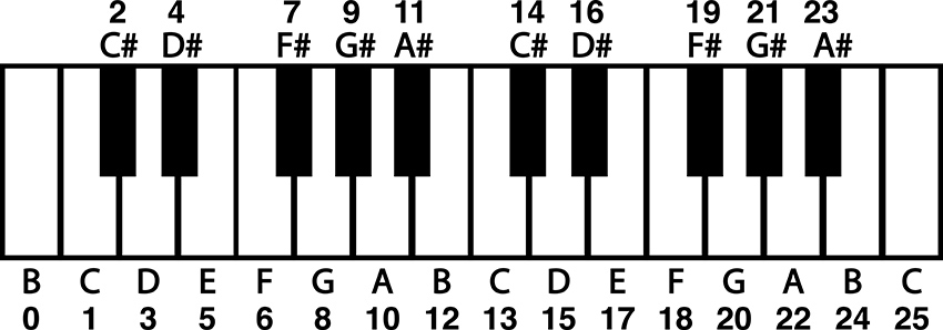
Figure 5 – Piano keyboard with note names and index values
To make a mask for C Major, we would simply use those numbers as the index of our chromatic scale array. To use a knob to play through the first octave of C Major, we could use the following code fragment:
										const byte octaveMask[] = {0, 12, 24, 36, 48, 60};

										const byte cMajorMask[8] = {1, 3, 5, 6, 8, 10, 12, 13};

										int octave = 2;

										int rawKnob = analogRead(noteKnob);

										int i = map(rawKnob, 0, 1023, 0, 7);  //note, only 8 notes in one octave of a major scale

										int degreeIndex = cMajorMask[i];

										pitchNum = octaveMask[octave] + degreeIndex; //this gives the octave, scale degree and root

										note = chromaticScale[pitchNum];

										tone(tonePin, note);
It would again be impractical to make a mask for every possible major scale at every tonic. So, we need to adjust this mask to make it usable for major scales starting on any note. To do that, we need to make the mask start at zero. That way the scale with a root of C is accessed by using the degree index plus a root offset of 1. So, if we subtract one from each item in the array, we get a major scale mask that starts at zero and can be offset to start at any note by changing the root value, just like the chromatic scale mask in the previous illustration. The resulting fragment will play a C major scale at the third octave. Change the root and octave to hear other major scales.
										const byte octaveMask[] = {0, 12, 24, 36, 48, 60};

										const byte majorMask[8] = {0, 2, 4, 5, 7, 9, 11, 12};

										int root = 1;

										int octave = 2;

										int rawKnob = analogRead(noteKnob);

										int i = map(rawKnob, 0, 1023, 0, 7);  //note, only 8 notes in one octave of a major scale

										int degreeIndex = majorMask[i];

										pitchNum = octaveMask[octave] + degreeIndex + root; //this gives the octave, scale degree and root

										note = chromaticScale[pitchNum];

										tone(tonePin, note);
The rest of this code establishes arrays for alternative scales and uses if statements to select from among the scales and respond to button presses. For more info on how if statements work, see earlier examples or check out the documentation built into Arduino’s IDE and on the web.
This quantizer is a useful proof of concept and can be included in other projects to make flexible and performable interfaces. Quantizers can be particularly useful when connecting the microcontroller hardware to other digital instruments using MIDI (Musical Instrument Digital Interface). MIDI divides the frequency space into MIDI note numbers, which can be packed up in array and called using the same basic mechanism described here.
Circuit Three: Four Digital Outputs for Rhythm Generation and Noisy Swarms
Overview
The following circuit creates four individual patterns of pulses visualized by four LEDs. Different patterns can be selected for the four channels using a potentiometer. The speed of the blinking is controlled by a second potentiometer and the length of the individual blinks are controlled by a third. These four channels are attached to four 1/8” output jacks that can be connected to other circuits to be used as gate signals (0v - +5V range) or connected to a mixer and used as linked polyphonic audio channels.
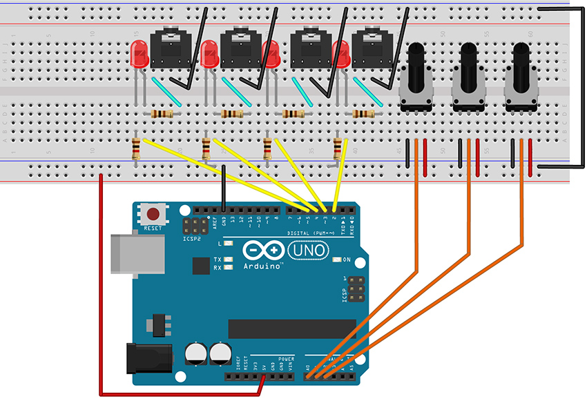
Figure 6 – Fritzing breadboard image of rhythm generation circuit
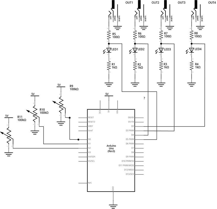
Figure 7 – Fritzing schematic of rhythm generation circuit
You will need:
- An Arduino Uno.
- A computer running the Arduino IDE software.
- A USB cable that can connect from your computer to the Uno’s USB type-B connector.
- A breadboard.
- Some solid hookup wire or premade wire jumpers.
- At least 4 100Ω resistors and at least 4 1kΩ resistors
- At least 4 LEDs (Light Emitting Diodes).
- An audio amplifier.
- Some kind of circuit that can respond to 5-volt gates/triggers.
- Assorted jacks and plugs, to match your amplifier.
- Hand tools.
Connect the Hardware
- Open Fritzing File [link] and navigate to Breadboard view
- Insert all components into breadboard matching image
- Connect all wires on breadboard
- Connect wires from Arduino to breadboard
- Visually Double-check all connections and wiring
- Connect the Arduino Uno to your Computer
Project Five: Quad Gate Generator
Program the Arduino with the QuadGATES sketch.
- Open the Arduino sketch [link]
- Click the upload button near the top left of the sketch window
									////////////

									//This code generates four patterns of 16 beats each.

									//LEDs blink to indicate the patterns of voltage.

									//1/8-inch jacks allow the signals to be used as gates or triggers

									//in an extended modular system.

									//

									//Knob 1 controls the master clock

									//Knob 2 picks from the preset patterns

									//Knob 3 sets the length of the triggers/gates - turning the knob all the way up creates ties

									//

									//The code is written so that each gate channel’s pattern number and trigger length can be

									//changed independently. Additional knobs would provide more variety and performance control.

									//For example, instead of one knob selecting the pattern number for all four channels, each of four

									// knobs can select the pattern number of a single channel, allowing for mixing patterns

									//////////////
									//The following variable MUST be defined as a const because it is used as the size of an array.

									//using a dynamic variable in the array size is not possible

									//this type of variable is often written in all caps

									const byte PATTERN_COUNT = 5; //if you create more patterns, change this number
									//this variable is an unsigned long because it is going to keep track of milliseconds

									//it will get very large while the program is running.

									unsigned long counter = 0;  //variable to keep track of the time
									int beat = 0; //index variable to keep track of the current step in the 16-beat pattern
									const int out1 = 2; //variables for pin connections for the gate outputs

									const int out2 = 3;

									const int out3 = 4;

									const int out4 = 5;
									const int clockKnob = A0; //variables for pin connections to knobs

									const int patternKnob = A1;

									const int lengthKnob = A2;
									int stepTime;  //variables to keep track of the mapped knob values

									int patternNum;

									int trigLength;
									//2-dimensional arrays to keep track of several 16-beat patterns per gate channel

									//1 means set a channel HIGH, 0 means set a channel LOW

									bool gateOnePatterns[][16] = {

									  {1, 0, 0, 0, 0, 0, 0, 0, 1, 0, 0, 0, 0, 0, 0, 0},

									  {1, 0, 0, 0, 0, 0, 0, 0, 1, 0, 0, 0, 0, 0, 0, 0},

									  {0, 0, 0, 0, 1, 0, 0, 0, 1, 0, 0, 0, 0, 1, 0, 1},

									  {1, 0, 0, 0, 1, 0, 0, 0, 1, 0, 0, 0, 1, 0, 1, 0},

									  {1, 1, 1, 1, 1, 1, 1, 1, 1, 1, 1, 1, 1, 1, 1, 1}

									};
									bool gateTwoPatterns[][16] = {

									  {0, 0, 0, 1, 0, 0, 0, 0, 0, 0, 0, 1, 0, 0, 0, 0},

									  {0, 0, 0, 1, 0, 0, 1, 0, 0, 0, 0, 1, 0, 0, 1, 0},

									  {1, 1, 1, 0, 1, 1, 0, 0, 1, 1, 0, 1, 1, 0, 1, 1},

									  {0, 0, 1, 1, 0, 0, 1, 0, 0, 0, 1, 1, 0, 1, 1, 1},

									  {1, 1, 1, 1, 1, 1, 1, 1, 1, 1, 1, 1, 1, 1, 1, 1}

									};
									bool gateThreePatterns[][16] = {

									  {0, 1, 0, 0, 0, 0, 0, 0, 0, 1, 0, 0, 0, 0, 0, 0},

									  {1, 0, 1, 0, 1, 0, 1, 0, 1, 1, 1, 0, 1, 0, 1, 0},

									  {1, 0, 0, 0, 0, 0, 0, 0, 1, 0, 0, 0, 0, 0, 0, 0},

									  {1, 0, 1, 1, 0, 1, 1, 0, 0, 0, 1, 1, 0, 1, 1, 1},

									  {1, 1, 1, 1, 1, 1, 1, 1, 1, 1, 1, 1, 1, 1, 1, 1}

									};
									bool gateFourPatterns[][16] = {

									  {0, 0, 1, 0, 0, 0, 0, 0, 0, 0, 1, 0, 0, 0, 0, 0},

									  {1, 0, 1, 0, 1, 1, 1, 0, 1, 0, 1, 0, 1, 1, 1, 1},

									  {1, 0, 1, 0, 1, 0, 1, 0, 1, 0, 1, 0, 1, 0, 1, 0},

									  {0, 1, 0, 1, 0, 1, 0, 1, 0, 1, 0, 1, 0, 1, 0, 1},

									  {1, 1, 1, 1, 1, 1, 1, 1, 1, 1, 1, 1, 1, 1, 1, 1}

									};

									void setup() {

									  pinMode(out1, OUTPUT);  //set gate pins as outputs

									  pinMode(out2, OUTPUT);

									  pinMode(out3, OUTPUT);

									  pinMode(out4, OUTPUT);

									}
									void loop() {

									  //Read Knobs and store raw values

									  int clockRaw = analogRead(clockKnob);

									  int patternRaw = analogRead(patternKnob);

									  int lengthRaw = analogRead(lengthKnob);
									  //Scale Raw values to desired ranges using the map() function

									  stepTime = map(clockRaw, 0, 1023, 1000, 30); //set a clock from 1000ms between beats to 30ms (make the 1000 and 30 smaller for oscillator-like effects)

									  patternNum = map(patternRaw, 0, 1023, 0, PATTERN_COUNT - 1); //select from patterns numbered 0 - 4

									  trigLength = map(lengthRaw, 0, 1023, 5, stepTime); //select trig lengths from 5ms to a full beat length
									  //keep track of time with custom function: stepper()

									  stepper(stepTime);
									  //write outputs high and low with custom function: trigger()

									  trigger(1, patternNum, trigLength);

									  trigger(2, patternNum, trigLength);

									  trigger(3, patternNum, trigLength);

									  trigger(4, patternNum, trigLength);
									}
									  //master timer function keeps track of which beat to play and keeps a running timer

									  void stepper(unsigned long stepDur) {

									    static unsigned long previousTime = 0;

									    counter = millis() - previousTime;  //counter counts up from 0 to whatever the step time has been set to


									    if (counter >= stepDur) { //if the counter reaches the stepTime, do the following:

									      beat++;             //increment the beat by one

									      previousTime = millis(); //update previousTime to right now

									      if (beat > 15) {      //if the beat reaches 16, start over at 0

									        beat = 0;

									      }

									    }

									  }
									//Custom Function to produce triggers of different lengths

									//The switch structure looks for which Gate Output number ("out")

									//then assigns a pattern number(patternNum) from a 2D array

									//then keeps track of how long to keep the Gate HIGH by comparing the trigLength ("dur") to the current

									//time of the counter (which is updated each time through the loop by the "stepper()" function)

									void trigger(int out, int patternNum, int dur) {

									  switch (out) {

									    case 1: //if the first argument ("out") is "1", do the following:

									      //check to see if the counter is less than the note length

									      //AND (&&) that the pattern indicates a "1". If so, write the output HIGH to 5V

									      if (counter < dur && gateOnePatterns[patternNum][beat] == 1) {

									        digitalWrite(out1, HIGH);

									      }
									      else if (gateOnePatterns[patternNum][beat] == 0) {

									        digitalWrite(out1, LOW);

									      }
									      //if the above cases are not true, and the trigLength is equal to the step length,

									      //don't turn the gate off at the end of the step. This will create a tie between adjacent "1"s

									      //in a pattern when the length knob is turned all the way to maximum

									      else if (stepTime == trigLength) {

									        //if the gate duration is all the way up, don't toggle the gate LOW

									      }
									      //in any other case, write the gate LOW once the counter passes dur

									      else {

									        digitalWrite(out1, LOW);

									      }

									      break;
									    case 2:

									      if (counter < dur && gateTwoPatterns[patternNum][beat] == 1) {

									        digitalWrite(out2, HIGH);

									      }
									      else if (gateTwoPatterns[patternNum][beat] == 0) {

									        digitalWrite(out2, LOW);

									      }
									      else if (stepTime == trigLength) {

									        //if the gate duration is all the way up, don't toggle the gate LOW

									      }

									      else {

									        digitalWrite(out2, LOW);

									      }

									      break;
									    case 3:

								      if (counter < dur && gateThreePatterns[patternNum][beat] == 1) {

								        digitalWrite(out3, HIGH);

								      }
									      else if (gateThreePatterns[patternNum][beat] == 0) {

									        digitalWrite(out3, LOW);

									      }
									      else if (stepTime == trigLength) {

									        //if the gate duration is all the way up, don't toggle the gate LOW

									      }

									      else {

									        digitalWrite(out3, LOW);

									      }

									      break;
									    case 4:

									      if (counter < dur && gateFourPatterns[patternNum][beat] == 1) {

									        digitalWrite(out4, HIGH);

									      }
									      else if (gateFourPatterns[patternNum][beat] == 0) {

									        digitalWrite(out4, LOW);

									      }
									      else if (stepTime == trigLength) {

									        //if the gate duration is all the way up, don't toggle the gate LOW

									      }

									      else {

									        digitalWrite(out4, LOW);

									      }

									      break;
									    default:

									      break;

									  }

									}
									//**********END OF CODE
What's Happening?
In this circuit, each of the four signal outputs are toggled HIGH and LOW by pre-programmed patterns (as visualized by the 4 LEDs). In the example, each of the four channels has 5 selectable patterns of 16 beats each. (There could be any number of patterns or beats, though.) There are three knobs that control the following: the speed of stepping, which pattern is selected for each channel, and how long each blink lasts in each step (When the blink time is all the way up, adjacent blinks tie together for longer notes).
The code starts with variable declarations as described in the comments within the code itself.
The setup() function repeats the instruction pinMode(pin, OUTPUT); four times to set each of the pins for the four channels to function as outputs.
The loop() is relatively short with the first three instructions reading the three knobs and storing those values in variables.
										  //Read Knobs and store raw values

									  int clockRaw = analogRead(clockKnob);

									  int patternRaw = analogRead(patternKnob);

									  int lengthRaw = analogRead(lengthKnob);
Then three more lines map those three variables to desired ranges for the speed, pattern number, and pulse length parameters.
										  //Scale Raw values to desired ranges using the map() function

										  stepTime = map(clockRaw, 0, 1023, 1000, 30); //set a clock from 1000ms between beats to 30ms

										  patternNum = map(patternRaw, 0, 1010, 0, PATTERN_COUNT - 1); //select from patterns numbered 0 - 4

										  trigLength = map(lengthRaw, 0, 1023, 5, stepTime); //select trig lengths from 5ms to a full beat length
Note that the stepTime variable is mapped to a range of 1000ms to 30ms. These values were chosen to taste. Experiment with by changing the last two numbers of the map function to find a desirable range. Making the numbers larger will allow for slower tempo settings. Setting both numbers shorter will create noisy oscillator effects if channel outputs are connected to your mixer and amplified speaker.
Custom Function 1: stepper()
The first major new concept in this code appears as a short instruction near the middle of the loop():
stepper(stepTime);
stepper() is not a built-in function of the Arduino language. This is a custom function that is created in this sketch. Custom functions are used relatively frequently and can be a convenient way to batch chunks of code into reusable pieces. I recommend heading over to the Arduino website’s reference on custom functions to look at their structure as you explore this next bit of description.
The stepper() function definition happens after the end of the loop function. It appears as follows:
										//master timer function keeps track of which beat to play and keeps a running timer

								void stepper(unsigned long stepDur) {

								  static unsigned long previousTime = 0;

								  counter = millis() - previousTime;  //counter counts up from 0 to whatever the step time has been set to
										  if (counter >= stepDur) { //if the counter reaches the stepTime, do the following:

										    beat++;             //increment the beat by one

										    previousTime = millis(); //update previousTime to right now

										    if (beat > 15) {      //if the beat reaches 16, start over at 0

										      beat = 0;

										    }

										  }

										}
This function starts with a data type declaration (just like variable declarations). This one is declared “void”. That means that whatever this function does, it is not going to report any new number for our sketch to use. Then we get to choose a name, in this case, “stepper”.
Now, our function can have as many arguments as we want. These are parameters that we might want to be able to change while our loop is running. Just like tone() has an argument for the pin, and an argument for the frequency, we gave stepper() an argument for the step time (kind of like the delay time in the earlier Blink sketch, but better). By defining this parameter, we are enabling the stepping speed to be changed dynamically by sending it the value of a knob or some other input sensor.
Since we are going to use this to keep track of time, we declare the argument’s data type as an unsigned long, and choose the name “stepDur”, for step duration. Note, when we create arguments for custom functions, they must be declared just like variables, but they have to be unique to the function. We can’t use a variable we already declared and pass that value. We have to make something new just for this function. To use this argument, we will add stepDur to an instruction later in the body of the function.
Next an open curly brace starts the body of the function. The first thing that happens in the function is the declaration of a variable called previousTime.
static unsigned long previousTime = 0;
We will use this variable to keep track of what the time was when we last took a step. This is critical to creating a time-base for our project without using delay(). This variable is an unsigned long because we are keeping track of the number of milliseconds since the project was powered on. This number will get quite large, and unsigned longs can store numbers just past four million. One thing that is new and noteworthy about this variable declaration is that it is declared as static. This is important, because this function gets activated (or called) each time the stepper() appears in the loop (including every time the loop repeats, which could be thousands of time per second). Each time a variable declaration happens, even declarations in custom functions, the variable gets set to the number it is listed as being equal to - in this case 0. However, we don’t want to reset to 0 every time the function is called, so the word static tells the function not to reinitialize, or reset, the value of this variable every time the function is called.
In the next line the variable “counter” is used to store the number of milliseconds since the last step. It is a global variable, meaning it was declared at the beginning of the code, outside of any functions. This allows it to be used in any function in the body of the sketch. We update it here, and we check it in other functions.
counter = millis() - previousTime;
millis() is a function that returns the number of milliseconds since the program began. So millis() can be thought of as the current clock time. In the above line of code, the current clock – previousTime (which was set to zero at the start), will equal the current clock and it will continue to increase the number of counter until something causes previousTime to be updated.
The rest of the function happens in the following if statement:
											if (counter >= stepDur) { //if the counter reaches the stepTime, do the following:

								      beat++;             //increment the beat by one

								      previousTime = millis(); //update previousTime to right now

								      if (beat > 15) {      //if the beat reaches 16, start over at 0

								        beat = 0;

								      }

								    }
Here is where we use the stepDur argument. This statement checks to see if the counter (the running tally of the number of milliseconds since the last step) is greater than or equal to the stepDur argument that we passed to the function. If so, another global variable called “beat” increments up by one (beat++;). Then our static variable previousTime gets set equal to the current program time in the line:
previousTime = millis(); //update previousTime to right now
This is how the counter will keep track of the time since the last step. Consider the following case: The device has just powered on and the program just started. millis() is counting up from zero. If our stepDur is 1000, then once the counter gets up to 1000, the beat variable will increase by one and then the above line of code will set previousTime equal to 1000. Since millis() just keeps counting up forever, the next time the function gets called it will be at some value greater than 1000, let’s say 1002. Recall:
counter = millis() - previousTime;
If millis() is at 1002 and previousTime is at 1000, then the counter is now back down at 2 and ready to count back up to stepDur before resetting again. Counter is always the difference between the time now and the time of the last step. This is how we keep track of time without using the delay() function blocking all our code.
										The last thing in our stepper function is inside of the previous if statement:
										if (beat > 15) {      //if the beat reaches 16, start over at 0

								        beat = 0;

								      }
The beat variable is going to be used to step through an array of 16 beats. Index values of 0 – 15 will address each beat in a pattern. This line of code says that if the beat is greater than 15, start over at 0. If patterns had 32 beats, this would be modified to read (beat > 31).
Custon Function 2: trigger()
After the definition of the stepper function, a new custom function called trigger() is defined. This tells our program what to do at each of the four outputs.
										//Custom Function to produce outputs of different lengths

										//The switch…case structure looks for which Output number ("out")

										//then assigns a pattern number(patternNum) from a 2D array

										//then keeps track of how long to keep the Output HIGH by comparing the trigLength ("dur") to the

										//current time of the counter - which is updated each time through the loop by the "stepper()" function

										void trigger(int out, int patternNum, int dur) {

										  switch (out) {

										    case 1: //if the first argument ("out") is "1", do the following:

										      //check to see if the counter is less than the note length

										      //AND (&&) that the pattern indicates a "1". If so, write the output HIGH to 5V

										      if (counter < dur && gateOnePatterns[patternNum][beat] == 1) {

										        digitalWrite(out1, HIGH);

										      }
										      else if (gateOnePatterns[patternNum][beat] == 0) {

										        digitalWrite(out1, LOW);

										      }
										      //if the above cases are not true, and the trigLength is equal to the step length,

										      //don't turn the gate off at the end of the step. This will create a tie between adjacent "1"s

										      //in a pattern when the length knob is turned all the way to maximum

										      else if (stepTime == trigLength) {

										        //if the gate duration is all the way up, don't toggle the gate LOW

										      }
										      //in any other case, write the gate LOW once the counter passes dur

										      else {

										        digitalWrite(out1, LOW);

										      }

										      break;
										    case 2:

										      if (counter < dur && gateTwoPatterns[patternNum][beat] == 1) {

										        digitalWrite(out2, HIGH);

										      }
										      else if (gateTwoPatterns[patternNum][beat] == 0) {

										        digitalWrite(out2, LOW);

										      }
										      else if (stepTime == trigLength) {

										        //if the gate duration is all the way up, don't toggle the gate LOW

										      }

										      else {

										        digitalWrite(out2, LOW);

										      }

										      break;
										    case 3:

										      if (counter < dur && gateThreePatterns[patternNum][beat] == 1) {

										        digitalWrite(out3, HIGH);

										      }
										      else if (gateThreePatterns[patternNum][beat] == 0) {

										        digitalWrite(out3, LOW);

										      }
										      else if (stepTime == trigLength) {

										        //if the gate duration is all the way up, don't toggle the gate LOW

										      }

										      else {

										        digitalWrite(out3, LOW);

										      }

										      break;
										    case 4:

										      if (counter < dur && gateFourPatterns[patternNum][beat] == 1) {

										        digitalWrite(out4, HIGH);

										      }
										      else if (gateFourPatterns[patternNum][beat] == 0) {

										        digitalWrite(out4, LOW);

										      }
										      else if (stepTime == trigLength) {

										        //if the gate duration is all the way up, don't toggle the gate LOW

										      }

										      else {

										        digitalWrite(out4, LOW);

										      }

										      break;
										    default:

										      break;

										  }

										}
The trigger() function is declared void because it doesn’t report any number back to the sketch. The three arguments are integers named “out”, “patternNum”, and “dur”. An open curly brace indicates the start of the body of the function.
void trigger(int out, int patternNum, int dur) {
The out argument will be a number that specifies which output channel the function should be controlling. patternNum tells the function which of the channel’s 5 patterns to read from. And dur will tell the function how long to keep the channel’s output HIGH when the pattern array shows a 1.
The function uses a switch…case control structure to decide which portion of the code to execute. The first argument, out, is used to control which case gets activated within the switch structure. Since each of the four cases in the switch are identical (except for which channel they act on), we will just examine what happens in the first case. The main loop of the sketch ends with four calls to the trigger() function:
										 //write outputs high and low with custom function: trigger()

										  trigger(1, patternNum, trigLength);

										  trigger(2, patternNum, trigLength);

										  trigger(3, patternNum, trigLength);

										  trigger(4, patternNum, trigLength);
Since each of these passes a different number to the first argument, each will activate a different case in the switch structure. We will examine the first call:
trigger(1, patternNum, trigLength);
In this call, out is equal to 1, which will activate the first, and only the first, case of our switch. If out were equal to 2, it would activate the second case in our switch. Out = 3 would activate the third case, and out = 4 would activate the fourth case.
										switch (out) {

										    case 1: //if the first argument ("out") is "1", do the following:

										      //check to see if the counter is less than the note length

										      //AND (&&) that the pattern indicates a "1". If so, write the output HIGH to 5V

										      if (counter < dur && gateOnePatterns[patternNum][beat] == 1) {

										        digitalWrite(out1, HIGH);

										      }
										      else if (gateOnePatterns[patternNum][beat] == 0) {

										        digitalWrite(out1, LOW);

										      }
										      //if the above cases are not true, and the trigLength is equal to the step length,

										      //don't turn the gate off at the end of the step. This will create a tie between adjacent "1"s

										      //in a pattern when the length knob is turned all the way to maximum

										      else if (stepTime == trigLength) {

										        //if the gate duration is all the way up, don't toggle the gate LOW

										      }
										      //in any other case, write the gate LOW once the counter passes dur

										      else {

										        digitalWrite(out1, LOW);

										      }

										      break;
Case 1: starts with an if statement control structure. When activated, the body of this if statement toggles output 1 HIGH. This will only execute if the conditional statement in the parenthesis is true. In this case, the “AND” boolean operator, “&&”, indicates that the two conditions must both be true in order for this statement to execute and the output to be toggled HIGH.
First, “counter < dur” indicates that the counter must be less than the dur variable (which is the argument we pass to the function to tell how long to keep an output HIGH). This is how we are able to set the length of the output pulses. If the counter is greater than the desired pulse duration, the output will not be toggled HIGH).
Second, “gateOnePatterns[patternNum][beat] == 1” looks at the array for channel one to see if the current beat is a one. Consider the gateOnePatterns array:
										bool gateOnePatterns[][16] = {

										  {1, 0, 0, 0, 0, 0, 0, 0, 1, 0, 0, 0, 0, 0, 0, 0},

										  {1, 0, 0, 0, 0, 0, 0, 0, 1, 0, 0, 0, 0, 0, 0, 0},

										  {0, 0, 0, 0, 1, 0, 0, 0, 1, 0, 0, 0, 0, 1, 0, 1},

										  {1, 0, 0, 0, 1, 0, 0, 0, 1, 0, 0, 0, 1, 0, 1, 0},

										  {1, 1, 1, 1, 1, 1, 1, 1, 1, 1, 1, 1, 1, 1, 1, 1}

										};
Our conditional statement looks for a one in the current beat of the current pattern. patternNum is an argument that gets passed into the function from the main loop. The variable is set in the loop by the following instruction:
patternNum = map(patternRaw, 0, 1023, 0, PATTERN_COUNT - 1); //select from patterns numbered 0 - 4
This variable will be mapped from a knob reading range of 0 -1023 to the index range of our array. Since there are five patterns, we select from each of the rows by passing a number between 0 – 4 to the first bracket of the array. If patternNum == 2, we are looking at the third row of values, for example.
The variable “beat” in the second bracket position of the array tells us which item in the row we want to examine. “beat” gets set by the stepper() function. As an example, if patterNum is equal to 2 and beat is equal to 9, we are looking for the 10th item in the 3rd row, which is a 0 (in bold below). In this case, the channel would not be toggled high and the relevant line of code will be executed.
										bool gateOnePatterns[][16] = {

										  {1, 0, 0, 0, 0, 0, 0, 0, 1, 0, 0, 0, 0, 0, 0, 0},

										  {1, 0, 0, 0, 0, 0, 0, 0, 1, 0, 0, 0, 0, 0, 0, 0},

										  {0, 0, 0, 0, 1, 0, 0, 0, 1, 0, 0, 0, 0, 1, 0, 1},

										  {1, 0, 0, 0, 1, 0, 0, 0, 1, 0, 0, 0, 1, 0, 1, 0},

										  {1, 1, 1, 1, 1, 1, 1, 1, 1, 1, 1, 1, 1, 1, 1, 1}

										};
The next part of case 1 is a an else if statement. This is just like an if statement, except that it must follow another if statement and will only be evaluated if the previous if statement conditions are not met. This else if statement toggles the gate low if the step is a zero. In our previous example, the beat was a 0, so this is the statement that would be activated and the conditional statements that follow would be ignored. A beat of 0 will always toggle the output LOW.
										else if (gateOnePatterns[patternNum][beat] == 0) {

								        digitalWrite(out1, LOW);

								      }
Next, we have another else if statement. This one would only be evaluated if the current beat was a 1 and the counter was less than the dur variable. It states that if the stepTime is equal to the trigger length, don’t do anything. This is really just here to block the final else statement that follows. This will have the effect of tying together multiple adjacent 1s by keeping the output from being toggled low at the end of every step.
										      //if the above cases are not true, and the trigLength is equal to the step length,

										      //don't turn the gate off at the end of the step. This will create a tie between adjacent "1"s

										      //in a pattern when the length knob is turned all the way to maximum

										      else if (stepTime == trigLength) {

										        //if the gate duration is all the way up, don't toggle the gate LOW

										      }
										The final part of the first case is the else statement and case break.
										      //in any other case, write the gate LOW once the counter passes dur

										      else {

										        digitalWrite(out1, LOW);

										      }

										      break;
This else statement says that if none of the above are true, then toggle Output 1 LOW. Specifically, this is useful in cases where the pattern indicates a one, but the counter has become greater than the step duration. This will set the output low where it will stay until next time a 1 shows up in the pattern.
The break command tells the program not to look at any other cases and to leave the switch and do whatever comes after it. In this case, there is nothing else in the function, so the program leaves this function and heads back into the loop to execute the next instruction.
The final three instructions in the loop are just calling the trigger() function again, but each time it is looking at the next pattern array and toggling the next output channel. Since each of these trigger() calls are being passed the same variables for pattern number and the trigger length, they will seem strongly correlated and patterns may start to feel recognizable. More complex behavior can be generated by mixing and matching from different pattern numbers for different channels, and by changing how long triggers last for different channels. Simply read more knobs and map them to individual variables to be used as arguments for each of the different trigger() calls. For example, the six analog inputs of the Arduino could be set up as follows:
Knob on A0 will still control the stepping speed.
Knobs on A1 – A3 can be used to select different patterns for channels 1, 2, and the 3 and 4 channels can change together based on the A3 knob.
Knobs A4 and A5 can each select different trigger lengths and be used to alter channels 1+3 and 2+4 respectively.
Then the calls to trigger might look something like the following:
										  trigger(1, patternNum1, trigLength1);

										  trigger(2, patternNum2, trigLength2);

										  trigger(3, patternNum3, trigLength1);

										  trigger(4, patternNum3, trigLength2);
Using a microcontroller with more analog inputs, like the Arduino Mega, would allow unique knob control for each parameter. It is also worth mentioning that choosing 4 output channels was a relatively arbitrary decision. It is certainly possible to have more or fewer. Experiment to find the most suitable arrangement for your application.
If you don’t have a modular synthesizer lying around, it should be noted that this project pairs well with the 4093 NAND-based oscillators from an earlier chapter in the book. Connecting this project’s outputs to one of each of the four oscillator inputs of the 4093 can create a dynamic polyphonic tone generator. In fact, many of the CMOS projects from the book will work great with Arduino provided you power the chips from the 5-volt pin of the UNO. If you have 9V CMOS synths, you can probably control them safely with the output of this circuit, but you wouldn’t want to send anything back to the Uno from your synth – even by accident. Beware, applying more than 5 volts to any of the Uno’s analog or digital pins risks damage to your system.
Circuit 4: Basic Step Sequencing Using Delay
Overview
The following circuit uses multiple digital output pins to send manually-controlled voltages to an external voltage-controlled oscillator. This project is broken up so that functions are added over the course of several examples. This first example shows the basic mechanism for stepping through the outputs, activating one output at a time. Additional examples will modify this code to include a built-in oscillator and then a speed control knob.
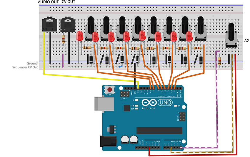
Figure 8 – Fritzing breadboard image of basic step sequencer
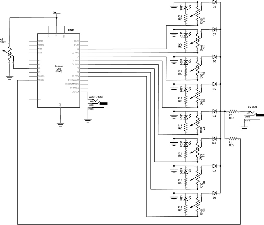
Figure 9 - Fritzing schematic of basic step sequencer
You will need:
- An Arduino Uno.
- A computer running the Arduino IDE software.
- A USB cable that can connect from your computer to the Uno’s USB type-B connector.
- A breadboard.
- Some solid hookup wire or premade wire jumpers.
- 10 1kΩ resistors.
- 9 10kΩ linear potentiometers.
- 8 LEDs (Light Emitting Diodes).
- 8 small signal diodes, such as 1N914.
- An audio amplifier.
- 2 jacks and plugs, to match your amplifier.
- Hand tools.
Connect the Hardware
- Open Fritzing File [link] and navigate to Breadboard view
- Insert all components into breadboard matching image
- Connect all wires on both breadboards
- Connect wires from Arduino to breadboards
- Visually Double-check all connections and wiring
- Connect the Arduino Uno to your Computer
Project Six_A: Basic Step Sequencing Using Delay
PROGRAM THE ARDUINO with the Programmable_Sequencer_A sketch.
- Open the Arduino sketch
- Click the upload button near the top left of the sketch window
								//CODE HEM_Programmable_Sequencer_A*********

								///////////////////

								//This code creates a programmable sequencer that steps through eight different output pins

								//The pins are attached to potentiometers which can be adjusted to provide stepped voltage

								//to the v/oct input of a VCO.

								///////////////////
								//Set up an ARRAY:

								//every time the program sees the word "steps[x]" it will

								//replace it with the "x" number in the list.

								//e.g. from the array below: steps[0] = 9, steps[1] = 8, steps[6] = 3, etc

								int steps[8] = {9, 8, 7, 6, 5, 4, 3, 2};  //the numbers represent the Arduino Digital Pins
								int stepTime = 200; //stepTime will be replaced by the number 200 - change this to change speed

								int stepNum = 0;    //this variable will keep track of which step is turned on.
								//The setup() is the first block of instructions that Arduino runs

								//It happens one time when the hardware is first powered on

								//Your sketch must have one and only one setup

								void setup() {

								  pinMode(steps[0], OUTPUT); //configure pin 9 as an output

								  pinMode(steps[1], OUTPUT); //configure pin 8 as an output

								  pinMode(steps[2], OUTPUT); //configure pin 7 as an output

								  pinMode(steps[3], OUTPUT);

								  pinMode(steps[4], OUTPUT);

								  pinMode(steps[5], OUTPUT);

								  pinMode(steps[6], OUTPUT);

								  pinMode(steps[7], OUTPUT);

								}
								//the  loop runs through each instruction, one at a time until it gets to the end.

								//then it loops back up to the top and does it again

								void loop() {
								  if (stepNum > 7) {

								    stepNum = 0;  //"0" is the first note, "1" is the second, and so on

								  }
								  //this is where the step gets turned on, the code paused, and then the step turned off again

								  digitalWrite(steps[stepNum], HIGH); //toggle selected pin (stepNum[0] = 9) to 5v (step 1 turns on)

								  delay(stepTime);                 //pause code for pre-determined number of milliseconds

								  digitalWrite(steps[stepNum], LOW);  //toggle selected pin to 0v (step 1 turns off)
								  stepNum ++;  //increment stepNum up by one

								}

								//**********END OF CODE
What's Happening?
This code functions in a very similar way to the ToneSEQ sketch in that it uses iteration to count through an array, so that at each new step of the array a new note can be played. (Though this first example will only produce notes if connected to an external voltage-controlled oscillator (VCO) via the CV output jack). One major difference between the ToneSEQ example and the project here is that this array does not include a list of notes, it instead includes a list of digital pins that are each toggled HIGH then LOW in turn. These pins are connected through resistors to LEDs that will light to indicate the current active step. The pins are also connected through potentiometers (knobs) that are manually adjusted so that each step will produce a different voltage (between 0 and about 5 volts). When a step is active, the potentiometer will have 0 volts on one end and 5 volts on the other. The knob can select any voltage in between 0 and 5 volts. When a step is inactive, it will have 0 volts on both ends, so the knob stays at zero volts regardless of its position. Each potentiometer’s wiper (this is the center leg – it acts as a kind of output in our scenario) is tied together (each goes through a diode first so that they will not interfere with each other) and that junction is connected to the CV output jack and the Uno’s own analog input pin #5.
The code starts by making sure that the step number it is going to turn on is within the range of the array:
								  if (stepNum > 7) {

								    stepNum = 0;  //"0" is the first note, "1" is the second, and so on

								  }
Since the code starts with stepNum = 0, this if statement is ignored for now.
The code turns steps on and off in the middle of the loop:
								//this is where the step gets turned on, the code paused, and then the step turned off again

								digitalWrite(steps[stepNum], HIGH); //toggle selected pin (stepNum[0] = 9) to 5v (step 1 turns on)

								delay(stepTime);                 //pause code for pre-determined number of milliseconds

								digitalWrite(steps[stepNum], LOW);  //toggle selected pin to 0v (step 1 turns off)
Each time through the loop, the digitalWrite() function toggles a pin HIGH based on what the stepNum index variable is. When the program starts, stepNum is 0, so steps[0] = 9. This will cause pin 9 to be toggled HIGH. Then the program waits for a certain number of milliseconds as defined by the variable, stepTime (change this at the beginning of the code to try different speeds). Once the delay has ended, the digitalWrite() function is used to toggle the pin LOW again.
Finally, once the pin has been toggled HIGH and toggled LOW again, the variable stepNum gets incremented up by one:
stepNum ++; //increment stepNum up by one
That means that stepNum will equal 1 now. The next time through the loop, steps[1] will address pin 8. Once all 8 pins have been toggled, stepNum++ will set stepNum equal to 8. The next time through the loop, the if statement at the beginning will see that 8 is greater than 7, and reset stepNum to 0 before the next step starts.
You can observe that this code is functioning by watching the pattern of LED lights. To hear anything though, the CV output of this circuit would need to be connected to an external oscillator. The next code example adds an internal oscillator to the project so tones can be produced at the audio output jack. We are going to use the tone() function to play a frequency based on what we read on analog pin 5. For a challenge, try to add this function yourself before moving forward. (Since the next example is just modifying the current code, the additions and deletions have been highlighted to make them easier to locate.)
Project Six_B: Add Internal Oscillator to Basic Sequencer
PROGRAM THE ARDUINO with the Programmable_Sequencer_B sketch.
- Open the Arduino sketch [link]
- Click the upload button near the top left of the sketch window
								//CODE HEM_Programmable_Sequencer_B******

								///////////////////

								//This code adds an internal oscillator to the stepping logic of the previous sketch

								///////////////////
								//Set up an ARRAY:

								//every time the program sees the word "steps[x]" it will

								//replace it with the "x" number in the list.

								//e.g. from the array below: steps[0] = 9, steps[1] = 8, steps[6] = 3, etc

								int steps[8] = {9, 8, 7, 6, 5, 4, 3, 2};  //the numbers represent the Arduino Digital Pins
								int stepTime = 200; //stepTime will be replaced by the number 200 - change this to change speed

								int stepNum = 0;    //this variable will keep track of which step is turned on.
								const int CVPin = A5;     //Analog Input Pin to read CV

								const int tonePin = 13;   //Output pin to produce tone

								int note;
								//The setup() is the first block of instructions that Arduino runs

								//It happens one time when the hardware is first powered on

								//Your sketch must have one and only one setup

								void setup() {

								  pinMode(steps[0], OUTPUT); //configure pin 9 as an output

								  pinMode(steps[1], OUTPUT); //configure pin 8 as an output

								  pinMode(steps[2], OUTPUT); //configure pin 7 as an output

								  pinMode(steps[3], OUTPUT);

								  pinMode(steps[4], OUTPUT);

								  pinMode(steps[5], OUTPUT);

								  pinMode(steps[6], OUTPUT);

								  pinMode(steps[7], OUTPUT);

								}
								//the  loop runs through each instruction, one at a time until it gets to the end.

								//then it loops back up to the top and does it again

								void loop() {
								  if (stepNum > 7) {

								    stepNum = 0;  //"0" is the first note, "1" is the second, and so on

								  }
								  //this is where the step gets turned on, the code paused, and then the step turned off again

								  digitalWrite(steps[stepNum], HIGH); //toggle selected pin (stepNum[0] = 9) to 5v (step 1 turns on)

								  //get value of CV from pin A5

								  //Note: the (void) and the delay are there to deal with ghost voltages

								  //resulting from multiplexing of the ADC and the unbuffered circuitry.

								  //This problem could also be solved with additional circuitry

								  (void)analogRead(CVPin);

								  delay(8);

								  note = map(analogRead(CVPin), 0, 1023, 35, 1200);     //get frequency value by reading the A5 pin

								  tone(tonePin, note);                //write the note to the audio out

								  delay(stepTime);                 //pause code for pre-determined number of milliseconds

								  noTone(tonePin);

								  digitalWrite(steps[stepNum], LOW);  //toggle selected pin to 0v (step 1 turns off)


								  stepNum ++;  //increment stepNum up by one

								}

								//**********END OF CODE
What's Happening?
A new variable, tonePin, was created to represent the pin that our audio output jack will be connected to. This is the pin that the tone() function (described in previous examples) will produce its tone on. Additionally, a variable called note was declared so that we can scale our raw knob reading to a range of notes to provide to the tone() function.
The important new addition to the loop is as follows:
								  //get value of CV from pin A5

								  //Note: the (void) and the delay are there to deal with ghost voltages

								  //resulting from multiplexing of the ADC and the unbuffered circuitry.

								  //This problem could also be solved with additional hardware

								  (void)analogRead(CVPin);

								  delay(8);

								  note = map(analogRead(CVPin), 0, 1023, 35, 1200);     //get frequency value by reading the A5 pin

								  tone(tonePin, note);                //write the note to the audio out

								  delay(stepTime);                 //pause code for pre-determined number of milliseconds

								  noTone(tonePin);

								  digitalWrite(steps[stepNum], LOW);  //toggle selected pin to 0v (step 1 turns off)
This is where we read the voltage of the current step, map it, and apply it to the frequency argument of the tone() function.
There is a little bit of funny business here due to the way the hardware is set up. If the analog pin is read directly it may carry over some voltage from the previous step’s reading. This ghost voltage would cause bad tracking of our steps. As mentioned in the comments, changing the circuit would solve this problem and make the (void)analogRead(CVPin); and delay(8); unnecessary. But every attempt was made to keep the hardware simple and affordable and two lines of code adequately addressed the problem and didn’t cost a penny.
Take note that another consequence of attempting to keep the hardware as minimal as possible is that the audio output and the CV output affect each other. If, while listening to the internal oscillator, you plug the CV into a v/oct input, you will notice a change in pitch of your internal oscillator’s notes. Buffering the voltage from the step knobs using an op amp could solve both the ghost voltage problem and the loading at the analogRead pin when the CV out is connected. This is certainly worth considering for anyone looking to make improvements. However, our current technique is great for quickly generating audio and CV from a relatively simple set of components.
Finally, the delay pauses the program, then noTone() to stops the current note and digitalWrite() toggles the step LOW.
The final addition we will make to this sequencer design is to add knob to control the speed of the stepping. Consider trying it for yourself before uploading the next example. The unused knob is attached to pin A2.
PROJECT SIX_C: Add Speed Control Knob to Basic Sequencer
PROGRAM THE ARDUINO with the Programmable_Sequencer_C sketch.
- Open the Arduino sketch
- Click the upload button near the top left of the sketch window
								//CODE HEM_Programmable_Sequencer_C******

								///////////////////

								//This code adds speed control knob to the stepping logic and in internal

								//oscillator of the previous sketch

								///////////////////
								//Set up an ARRAY:

								//every time the program sees the word "steps[x]" it will

								//replace it with the "x" number in the list.

								//e.g. from the array below: steps[0] = 9, steps[1] = 8, steps[6] = 3, etc

								int steps[8] = {9, 8, 7, 6, 5, 4, 3, 2};  //the numbers represent the Arduino Digital Pins
								int stepTime = 200; //the word stepTime will be replaced by the number 200 - change this to change speed

								int speedKnob = A2; //center pin of Speed knob is attached to pin A0

								int mappedSpeed;    //variable used to store a scaled version of the analog reading of the speed knob

								int stepNum = 0;    //this variable will keep track of which step is turned on.
								int CVPin = A5;     //Analog Input Pin to read CV

								int tonePin = 13;   //Output pin to produce tone

								int note;
								//The setup() is the first block of instructions that Arduino runs

								//It happens one time when the hardware is first powered on

								//Your sketch must have one and only one setup

								void setup() {

								  pinMode(steps[0], OUTPUT); //configure pin 9 as an output

								  pinMode(steps[1], OUTPUT); //configure pin 8 as an output

								  pinMode(steps[2], OUTPUT); //configure pin 7 as an output

								  pinMode(steps[3], OUTPUT);

								  pinMode(steps[4], OUTPUT);

								  pinMode(steps[5], OUTPUT);

								  pinMode(steps[6], OUTPUT);

								  pinMode(steps[7], OUTPUT);

								}
								//the  loop runs through each instruction, one at a time until it gets to the end.

								//then it loops back up to the top and does it again

								void loop() {
								  if (stepNum > 7) {

								    stepNum = 0;  //"0" is the frist note, "1" is the second, and so on

								  }
								  //Read the voltage on knob A0 and store the number (something between 0 and 1023) in the variable "stepTime"

								  stepTime = analogRead(speedKnob); //stepTime and speedKnob are variables declared before the setup()
								  //scale the stepTime variable to a new range that also reverses the direction so the min is higher than the max

								  //0 - 1023 are the min and max of the actual reading, 300 and 1 are the new min and max representing delay times in ms

								  mappedSpeed = map(stepTime, 0, 1023, 300, 1);
								  //this is where the step gets turned on, the code paused, and then the step turned off again

								  digitalWrite(steps[stepNum], HIGH); //toggle selected pin (stepNum[0] = 9) to 5v (step 1 turns on)

								  //get value of CV from pin A5

								  //Note: the (void) and the delay are there to deal with ghost voltages

								  //resulting from multiplexing of the ADC and the unbuffered circuitry.

								  //This problem could also be solved with additonal circuitry

								  (void)analogRead(CVPin);

								  delay(8);

								  note = map(analogRead(CVPin), 0, 1023, 35, 1200);     //get frequency value by reading the A5 pin

								  tone(tonePin, note);                //write the note to the audio out

								  delay(mappedSpeed);                 //pause code for the amount of time set by the knob (milliseconds)

								  digitalWrite(steps[stepNum], LOW);  //toggle selected pin to 0v (step 1 turns off)

								  noTone(tonePin);
								  stepNum ++;  //increment stepNum up by one
								}

								//**********END OF CODE
What's Happening?
The knob attached to A2 is now controlling the speed of the sequencer. The value read on pin A2 is stored in the variable stepTime. This variable is mapped to the new range of 300 to 1 (this range was set by ear and can be adjusted to taste) using the map() function, and then stored in the variable mappedSpeed. This new variable is then used in the delay function that sets the speed of the sequencer.
Conclusion
This 8-step sequencer is a relatively simple design and demonstrates the mechanics of the concept of generating analog outputs by combining digital signals and potentiometers. This example is severely limited by the use of the delay, though. The power of the microcontroller allows for many more features and options that can make our little beep machine into a performable instrument. In the final project of this series, the 8-Step Sequencer will be re-written to run without using a delay for its timing, allowing for a set of new features and enhancements to be explored.
CIRCUIT 5: 8-Step Performance Sequencer
Overview
The hardware for this project just expands what was already connected in the previous circuit by adding 3 additional knobs, 2 buttons, one switch, one additional digital output jack and one digital input jack with a transistor and two resistors to protect the microcontroller pin from unknown voltages.
The example sketches start by redesigning the stepping mechanics of the basic sequencer from the last project to function without using delay. Then, features are added a little bit at a time through a sequence of example sketches with the intention of showing how smaller techniques can be combined into larger, more complex projects. Each new sketch builds on the last and the location of code changes are indicated by the following: “//!!!”. While working through the examples, use the “find” feature in the Arduino IDE to look for the 3 exclamation points. They will show the changes and the nearby comments will explain the techniques.
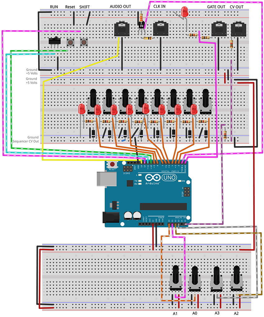
Figure 10 - Fritzing breadboard image of performance sequencer circuit
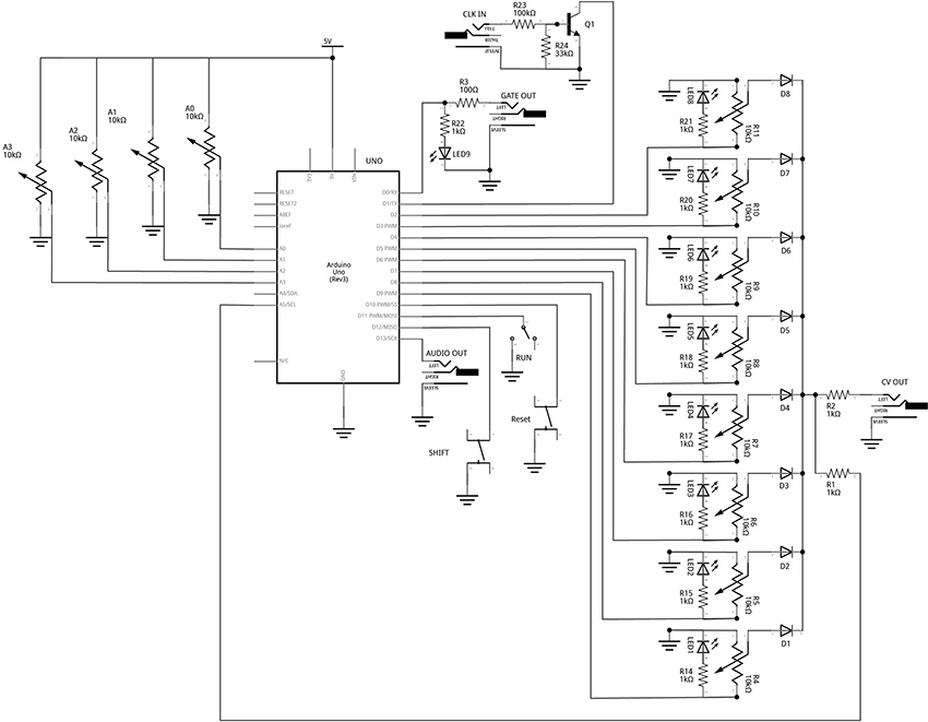
Figure 11 – Fritzing schematic of performance sequencer circuit
You will need:
- An Arduino Uno.
- A computer running the Arduino IDE software.
- A USB cable that can connect from your computer to the Uno’s USB type-B connector.
- Several breadboards.
- Some solid hookup wire or premade wire jumpers.
- 1 x 100kΩ, 1 x 33kΩ, 11 x 1kΩ, and 1 x 100Ω resistors (it is okay to use values that are within about 10 – 15% of these values.
- 12 10kΩ linear potentiometers.
- 9 LEDs (Light Emitting Diodes).
- 8 small signal diodes, such as 1N914.
- 1 toggle switch.
- 2 pushbuttons.
- An audio amplifier.
- 4 jacks and plugs, to match your amplifier and external modules.
- Hand tools.
Open the linked example sketches and look for the “!!!” in the comments:
PROJECT SEVEN_A: Step Sequencer: Controller (no delay)
PROGRAM THE ARDUINO with the A_SEQ_StepController sketch.
- Open the Arduino sketch
- Click the upload button near the top left of the sketch window
								/////////////////////////////////

								//This code shows how to use millis() to keep track of the time that has elapsed since the program started.

								//By comparing the current time to some known time in the past, we can keep a counter running to time our steps.

								//This lets us run a sequencer without using delay() enabling multiple things to happen simultaneously.

								//The sequencer turns on step[] pins in sequence. LEDs light up each step and show the pattern of the steps.

								//These pins also each go through a potentiometer that can set a unique voltage for each of the 8 steps.

								//These potentiometers are tied together through diodes so that steps do not affect each other.

								//The voltage of the current step should be sent to the v/oct input of a VCO to control the frequency of a tone.

								//In the next example, we will tie the output to an Analog Input pin of the Arduino to

								//control the pitch of a built-in tone as well.

								//////////////////////////////////
								//bool (boolean) data type stores a variable that only has two states: true or false

								bool stepStop = false;   //Is it time to STOP the current step?

								bool stepStart = false; //Is it time to START the next step?
								//Set up an ARRAY to represent the step pins of the sequencer:

								//every time the program sees the word "steps[n]" it will

								//replace it with the "n" number in the list.

								//e.g. from the array below: steps[0] = 9, steps[1] = 8, steps[6] = 3, etc

								int steps[8] = {9, 8, 7, 6, 5, 4, 3, 2};  //the numbers represent the Arduino Digital Pins

								int stepNum = 0; //variable to use as index for "steps[ ]"
								void setup() {

								  pinMode(steps[0], OUTPUT); //Configure pin 9 as an output

								  pinMode(steps[1], OUTPUT); //Configure pin 8 as an output

								  pinMode(steps[2], OUTPUT); //Configure pin 7 as an output

								  pinMode(steps[3], OUTPUT); //...

								  pinMode(steps[4], OUTPUT);

								  pinMode(steps[5], OUTPUT);

								  pinMode(steps[6], OUTPUT);

								  pinMode(steps[7], OUTPUT);

								}
								void loop() {

								  //stepController is a custom function that updates the variables startStep and stopStep

								  //the two arguments represent values for: 1. the speed of the steps, 2. the legth of the notes.

								  //knobs are read into the funtion where they are scaled and used to control the sequencer

								  //More details are in the body of the function declaration below (after the loop())

								  stepController(1000, 500);
								  //Check to see if the stepController reports that it is time to STOP the current note

								  if (stepStop == true) {

								    digitalWrite(steps[stepNum], LOW); //turn off the last step

								    stepStop = false; //reset the flag

								  }
								  //Check to see if the stepController reports that it is time to START the new note

								  if (stepStart == true) {

								    stepNum++; //add one to stepNum. "stepNum = stepNum + 1;" would do the same thing. Odd-only counting with stepNum +2;

								    if (stepNum > 7) {

								      stepNum = 0;

								    }

								    digitalWrite(steps[stepNum], HIGH); //turn on the next step

								    stepStart = false; //set our running state to indicate that we are not ready to start a new step

								  }
								}
								//CUSTOM STEPPING FUNCTION

								void stepController(int speedIn, int durIn) {
								  //Variables for Keeping Track of Time (unsigned long will allow us to store very large numbers)

								  static unsigned long previousTime = 0; //keep track of the time we last stepped

								  static unsigned long counter = 0;  //keep track of time since the last step

								  counter = millis() - previousTime;    //counter keeps track of the number of ms since last step began

								  int stepInterval = speedIn;   //speedIn is a variable used to pass numbers into this function from the main loop

								  int stepDuration = durIn;   //this is the gate duration. It should be less than the step interval
								  if (counter > stepDuration) { //check to see if we should STOP the previous step

								    stepStop = true;    //set flag to trigger the stop of the current step

								  }
								  if (counter >= stepInterval && stepStart == false) { //check to see if we should START the next step

								    stepStart = true;   //set flag to trigger the start of the next step

								    previousTime = millis(); //set new previous time to restart counter at beginning of each step

								  }
								  else {

								    stepStart = false;    //make it unambiguous that we should NOT start a new step if the above is not true

								  }

								}
This code uses a custom function to keep track of time. It takes two arguments, one for how long each step should last, and one for how long a note should stay on during each step. The mechanics are very similar to the stepper() function from the Quad Gate Generator example. It uses the millis() function to check the current time against the last time a step was taken. This function is a little bit different in that it sets flags that the rest of the program can check to see if it is time to start a step or if it is time to stop a step. Most of the time we are neither starting a step nor stopping a step.
PROJECT SEVEN_B: Step Sequencer: Internal Oscillator
PROGRAM THE ARDUINO with the B_SEQ_tone sketch.
- Open the Arduino sketch
- Click the upload button near the top left of the sketch window
								/////////////////////////////////

								//This code shows how to use millis() to keep track of the time that has elapsed since the program started.

								//By comparing the current time to some known time in the past, we can keep a counter running to time our steps.

								//This lets us run a sequencer without using delay(). This lets us affect multiple timings without pausing the code.

								//The sequencer turns on step[] pins in sequence. LEDs light up each step and show the pattern of the steps.

								//These pins also each go through a potentiometer that can set a unique voltage for each of the 8 steps.

								//These potentiometers are tied together through diodes so that steps do not affect each other.

								//The voltage of the current step should be sent to the v/oct input of a VCO to control the frequency of a tone.

								//The voltage is also tied to an Analog Input pin of the Arduino to

								//control the frequency of the built-in tone() function as well.

								//

								//Look for "!!!" to find changes

								//////////////////////////////////
								//bool (boolean) data type stores a variable that only has two states: true or false

								bool stepStop = false;   //Is it time to STOP the current step?

								bool stepStart = false; //Is it time to START the next step?
								//Set up an ARRAY to represent the step pins of the sequencer:

								//every time the program sees the word "steps[n]" it will

								//replace it with the "n" number in the list.

								//e.g. from the array below: steps[0] = 9, steps[1] = 8, steps[6] = 3, etc

								int steps[8] = {9, 8, 7, 6, 5, 4, 3, 2};  //the numbers represent the Arduino Digital Pins

								int stepNum = 0; //variable to use as index for "steps[ ]"
								//!!! variables related to the tones

								const int tonePin = 13;   //!!!Output pin to produce tone

								const int CVPin = A5;     //!!!Analog Input Pin to read CV

								int CVVal;      //!!!Variable to store the current level of the CV Input (read on A5)

								int note;           //!!!frequency for the tone() function to play
								void setup() {

								  pinMode(steps[0], OUTPUT); //Configure pin 9 as an output

								  pinMode(steps[1], OUTPUT); //Configure pin 8 as an output

								  pinMode(steps[2], OUTPUT); //Configure pin 7 as an output

								  pinMode(steps[3], OUTPUT);

								  pinMode(steps[4], OUTPUT);

								  pinMode(steps[5], OUTPUT);

								  pinMode(steps[6], OUTPUT);

								  pinMode(steps[7], OUTPUT);

								}
								void loop() {

								  //stepController is a custom function that updates the variables startStep and stopStep

								  //the two arguments represent knobs for: 1. the speed of the steps, 2. the legth of the notes.

								  //knobs are read into the funtion where they are scaled and used to control the sequencer

								  //More details are in the body of the function declaration below (after the loop())

								  stepController(1000, 500);
								  //Check to see if the stepController reports that it is time to STOP the current note

								  if (stepStop == true) {

								    digitalWrite(steps[stepNum], LOW); //turn off the last step

								    //!!!

								    noTone(tonePin);                    //stop tone

								    stepStop = false; //reset the flag

								  }
								  //Check to see if the stepController reports that it is time to START the new note

								  if (stepStart == true) {

								    stepNum++; //add one to stepNum. "stepNum = stepNum + 1;" would do the same thing. Odd-only counting with stepNum +2;

								    if (stepNum > 7) {

								      stepNum = 0;

								    }

								    digitalWrite(steps[stepNum], HIGH); //turn on the next step

								    stepStart = false; //set our running state to indicate that we are not ready to start a new step
								    //!!!get value of CV from pin A5

								    CVVal = analogRead(CVPin);

								    //!!!map function takes the original knob range (0 - 1023) and scales it to the range of the tone function (31 - 4878)

								    note = map(CVVal, 0, 1023, 31, 4878);

								    tone(tonePin, note);  //!!!produce the note to the audio out

								  }
								}
								//CUSTOM STEPPING FUNCTION

								void stepController(int speedIn, int durIn) {
								  //Variables for Keeping Track of Time (unsigned long will allow us to store very large numbers)

								  static unsigned long previousTime = 0; //keep track of the time we last stepped

								  static unsigned long counter = 0;  //keep track of time since the last step

								  counter = millis() - previousTime;    //counter keeps track of the number of ms since last step began

								  int stepInterval = speedIn;   //speedIn is a variable used to pass numbers into this function from the main loop

								  int stepDuration = durIn;   //this is the gate duration. It should be less than the step interval
								  if (counter > stepDuration) { //check to see if we should STOP the previous step

								    stepStop = true;    //set flag to trigger the stop of the current step

								  }
								  if (counter >= stepInterval && stepStart == false) { //check to see if we should START the next step

								    stepStart = true;   //set flag to trigger the start of the next step

								    previousTime = millis(); //set new previous time to restart counter at beginning of each step

								  }
								  else {

								    stepStart = false;    //make it unambiguous that we should NOT start a new step

								  }

								}
The major changes in this example involve the creation of a bunch of variables to handle connecting a reading the CV voltage and some for mapping the raw voltage to a range of frequencies that are useful in the tone() function. Then noTone() is called if the stepStop flag is true. tone() is called if the stepStart flag is true. If neither flag is true, the loop just keeps updating the stepController() function until something changes.
PROJECT SEVEN_C: Step Sequencer: Speed
PROGRAM THE ARDUINO with the C_SEQ_SpeedControl sketch.
- Open the Arduino sketch
- Click the upload button near the top left of the sketch window
								/////////////////////////////////

								//This code shows how to use millis() to keep track of the time that has elapsed since the program started.

								//By comparing the current time to some known time in the past, we can keep a counter running to time our steps.

								//This lets us run a sequencer without using delay(). This lets us affect multiple timings without pausing the code.

								//The sequencer turns on step[] pins in sequence. LEDs light up each step and show the pattern of the steps.

								//These pins also each go through a potentiometer that can set a unique voltage for each of the 8 steps.

								//These potentiometers are tied together through diodes so that steps do not affect each other.

								//The voltage of the current step should be sent to the v/oct input of a VCO to control the frequency of a tone.

								//The voltage is also tied to an Analog Input pin of the Arduino to

								//control the frequency of the built-in tone() function as well.

								//

								//!!! add speed control knob

								//////////////////////////////////
								//Variables for Keeping Track of Time (unsigned long will allow us to store very large numbers)

								unsigned long previousTime = 0; //keep track of the time we last stepped

								unsigned long counter = 0;  //keep track of time since the last step
								//bool (boolean) data type stores a variable that only has two states: true or false

								bool stepStop = false;   //Is it time to STOP the current step?

								bool stepStart = false; //Is it time to START the next step?
								//Set up an ARRAY to represent the step pins of the sequencer:

								//every time the program sees the word "steps[n]" it will

								//replace it with the "n" number in the list.

								//e.g. from the array below: steps[0] = 9, steps[1] = 8, steps[6] = 3, etc

								int steps[8] = {9, 8, 7, 6, 5, 4, 3, 2};  //the numbers represent the Arduino Digital Pins

								int stepNum = 0; //variable to use as index for "steps[ ]"
								//variables related to the tones

								const int tonePin = 13;   //Output pin to produce tone

								const int CVPin = A5;     //Analog Input Pin to read CV

								int CVVal;      //Variable to store the current level of the CV Input (read on A5)

								int note;           //frequency for the tone() function to play
								//!!!Variables for keeping track of stepping speed

								const int speedKnobPin = A2;
								void setup() {

								  pinMode(steps[0], OUTPUT); //Configure pin 9 as an output

								  pinMode(steps[1], OUTPUT); //Configure pin 8 as an output

								  pinMode(steps[2], OUTPUT); //Configure pin 7 as an output

								  pinMode(steps[3], OUTPUT);

								  pinMode(steps[4], OUTPUT);

								  pinMode(steps[5], OUTPUT);

								  pinMode(steps[6], OUTPUT);

								  pinMode(steps[7], OUTPUT);

								}
								void loop() {

								  //stepController is a custom function that updates the variables startStep and stopStep

								  //the two arguments represent knobs for: 1. the speed of the steps, 2. the legth of the notes.

								  //knobs are read into the funtion where they are scaled and used to control the sequencer

								  //More details are in the body of the function declaration below (after the loop())

								  stepController(speedKnobPin, speedKnobPin); //!!!Add knob pin variables to pass changes into function
								  //Check to see if the stepController reports that it is time to STOP the current note

								  if (stepStop == true) {

								    digitalWrite(steps[stepNum], LOW);  //turn off the last step

								    noTone(tonePin);                    //stop tone

								    stepStop = false;                   //reset the flag
								  }
								  //Check to see if the stepController reports that it is time to START the new note

								  if (stepStart == true) {

								    stepNum++; //add one to stepNum. "stepNum = stepNum + 1;" would do the same thing. Odd-only counting with stepNum +2;

								    if (stepNum > 7) {

								      stepNum = 0;

								    }


								    digitalWrite(steps[stepNum], HIGH); //turn on the next step

								    stepStart = false; //set our running state to indicate that we are not ready to start a new step
								    //get value of CV from pin A5

								    //!!!Note: the (void) and the delay are there to deal with ghost voltages

								    //resulting from multiplexing of the ADC and the unbuffered circuitry.

								    //changes to the hardware can make this unnecessary

								    (void)analogRead(CVPin);

								    delay(8);

								    CVVal = analogRead(CVPin);

								    note = map(CVVal, 0, 1000, 31, 4878);

								    tone(tonePin, note);  //write the note to the audio out

								  }
								}
								//CUSTOM STEPPING FUNCTION

								void stepController(int speedIn, int durIn) {
								  //Variables for Keeping Track of Time (unsigned long will allow us to store very large numbers)

								  static unsigned long previousTime = 0; //keep track of the time we last stepped

								  static unsigned long counter = 0;  //keep track of time since the last step

								  counter = millis() - previousTime;    //counter keeps track of the number of ms since last step began

								  int speedValRaw = analogRead(speedIn); //!!! read the speed knob and store the raw value

								  int stepInterval = map(speedValRaw, 0, 1023, 300, 10); //!!! map the value to new speeds (chosen by ear)

								  int durValRaw = analogRead(durIn);  //!!! read the duration knob and store the raw value

								  int stepDuration = map(durValRaw, 0, 1023, 0, stepInterval - 1); //!!! map the duration knob to a new range from very short to an entire step - 1ms
								  if (counter > stepDuration) { //check to see if we should STOP the previous step

								    stepStop = true;    //set flag to trigger the stop of the current step

								  }
								  //!!! Add an if statment to check for the knob to be at Zero. If so, stop the sequencer

								  if (speedValRaw != 0) { //if knob is not set to 0, it sets the speed of the sequencer

								    if (counter >= stepInterval && stepStart == false) { //check to see if we should START the next step

								      stepStart = true;   //set flag to trigger the start of the next step

								      previousTime = millis(); //set new previous time to restart counter at beginning of each step

								    }
								    else {

								      stepStart = false;    //make it unambiguous that we should NOT start a new step

								    }

								  }

								  else { //if knob is at zero, stop sequencer

								    stepStart = false;

								    stepStop = false;

								  }

								}
In this example, the value read from a knob attached to A2 is passed into both arguments of the stepController() function. This will use the same value to control the speed of the stepping and the length of the steps. Experiment with using a second knob for the second argument.
Inside the stepController(), the analog pin is read and then mapped to values that are appropriate for the two parameters.
								  int speedValRaw = analogRead(speedIn); //!!! read the speed knob and store the raw value

								  int stepInterval = map(speedValRaw, 0, 1023, 300, 10); //!!! map the value to new speeds (chosen by

								ear)
Note above, the stepInterval (the speed of stepping) is mapped to my taste. Change the last two numbers in the map function to experiment with different speed control.
								  int durValRaw = analogRead(durIn);  //!!! read the duration knob and store the raw value

								  int stepDuration = map(durValRaw, 0, 1023, 1, stepInterval - 1); //!!! map the duration knob to a new range from very short to an entire step - 1ms
Also note that the durations are automatically scaled based on the step interval and are able to be set from as little as 1 ms to as great as an entire step interval minus one millisecond. This is useful for keeping the start and stop flags unambiguous.
The final thing to mention is that this code stops the sequencer when the knob is all the way down. This is used as a pause function for now. Later this knob position will be where we add a mode to read an external clock signal.
PROJECT SEVEN_D: Step Sequencer: Gate Output
PROGRAM THE ARDUINO with the D_SEQ_GateOutput sketch.
- Open the Arduino sketch
- Click the upload button near the top left of the sketch window
								/////////////////////////////////

								//This code creates an 8-step CV sequencer with and internal oscillator, speed control,

								//and a Gate Output

								//

								//!!! add Gate Output and make steps stay on full duration for CV output

								//turning the Gate Off instead of turning the step off will allow an externally connected

								//Oscillator to function correctly. Otherwise, it will be given two pitches for each step - the

								//pitch selected by the knob when the step is high, and a pitch for zero volts when the step is low

								//////////////////////////////////
								//bool (boolean) data type stores a variable that only has two states: true or false

								bool stepStop = false;   //Is it time to STOP the current step?

								bool stepStart = false; //Is it time to START the next step?
								//Set up an ARRAY to represent the step pins of the sequencer:

								//every time the program sees the word "steps[n]" it will

								//replace it with the "n" number in the list.

								//e.g. from the array below: steps[0] = 9, steps[1] = 8, steps[6] = 3, etc

								int steps[8] = {9, 8, 7, 6, 5, 4, 3, 2};  //the numbers represent the Arduino Digital Pins

								int stepNum = 0; //variable to use as index for "steps[ ]"

								int prevStepNum = 0; //!!!variable to store the previous step number

								//variables related to the tones

								const int tonePin = 13;   //Output pin to produce tone

								const int CVPin = A5;     //Analog Input Pin to read CV

								int CVVal;      //Variable to store the current level of the CV Input (read on A5)

								int note;           //frequency for the tone() function to play
								//Variables for keeping track of stepping speed

								const int speedKnobPin = A2;
								const int gatePin = 0;    //!!!pin to produce a digital gate out
								void setup() {

								  pinMode(steps[0], OUTPUT); //Configure pin 9 as an output

								  pinMode(steps[1], OUTPUT); //Configure pin 8 as an output

								  pinMode(steps[2], OUTPUT); //Configure pin 7 as an output

								  pinMode(steps[3], OUTPUT);

								  pinMode(steps[4], OUTPUT);

								  pinMode(steps[5], OUTPUT);

								  pinMode(steps[6], OUTPUT);

								  pinMode(steps[7], OUTPUT);
								  pinMode(gatePin, OUTPUT);
								}
								void loop() {

								  //stepController is a custom function that steps the variables startStep and stopStep

								  //the two numbers represent 1. the speed of the steps and 2. the length of the notes.

								  //knobs are read into the function where they are scaled and used to control the sequencer

								  //More details are in the body of the function declaration below (after the loop())

								  stepController(speedKnobPin, speedKnobPin);
								  //Check to see if the stepController reports that it is time to STOP the current note

								  if (stepStop == true) {

								    //digitalWrite(steps[stepNum], LOW);  //!!! This moves to right before a new step

								    noTone(tonePin);                    //stop tone

								    digitalWrite(gatePin, LOW);         //!!!toggle GATE LOW instead of turning off step

								    stepStop = false;                   //reset the flag

								  }
								  //Check to see if the stepController reports that it is time to START the new note

								  if (stepStart == true) {

								    stepNum++; //add one to stepNum. "stepNum = stepNum + 1;" would do the same thing. Odd-only counting with stepNum +2;

								    if (stepNum > 7) {

								      stepNum = 0;

								    }

								      digitalWrite(steps[prevStepNum], LOW); //!!!turn off the last step
								      digitalWrite(steps[stepNum], HIGH); //!!!turn on the next step

								      prevStepNum = stepNum;   //!!! save this step so we can turn it off before the next new one.

								      stepStart = false; //set our running state to indicate that we are not ready to start a new step

								    //get value of CV from pin A5

								    //Note: the (void) and the delay are there to deal with ghost voltages

								    //resulting from multiplexing of the ADC and the unbuffered circuitry.

								    //changes to the hardware can make this unnecessary

								    (void)analogRead(CVPin);

								    delay(8);

								    CVVal = analogRead(CVPin);

								    note = map(CVVal, 0, 1000, 31, 4878);

								    tone(tonePin, note);  //write the note to the audio out

								    digitalWrite(gatePin, HIGH);  //!!!turn the gate signal to +5V

								  }
								}
								//CUSTOM STEPPING FUNCTION

								void stepController(int speedIn, int durIn) {
								  //Variables for Keeping Track of Time (unsigned long will allow us to store very large numbers)

								  static unsigned long previousTime = 0; //keep track of the time we last stepped

								  static unsigned long counter = 0;  //keep track of time since the last step

								  counter = millis() - previousTime;    //counter keeps track of the number of ms since last step began

								  int speedValRaw = analogRead(speedIn); //read the speed knob and store the raw value

								  int stepInterval = map(speedValRaw, 0, 1023, 300, 10); //map the value to new speeds (chosen by ear)

								  int durValRaw = analogRead(durIn);  //read the duration knob and store the raw value

								  int stepDuration = map(durValRaw, 0, 1023, 0, stepInterval - 1); //map the duration knob to a new range from very short to an entire step - 1ms
								  if (counter > stepDuration) { //check to see if we should STOP the previous step

								    stepStop = true;    //set flag to trigger the stop of the current step

								  }
								  //Add an if statment to check for the knob to be at Zero. If so, stop the sequencer

								  if (speedValRaw != 0) { //if knob is not set to 0, it sets the speed of the sequencer

								    if (counter >= stepInterval && stepStart == false) { //check to see if we should START the next step

								      stepStart = true;   //set flag to trigger the start of the next step

								      previousTime = millis(); //set new previous time to restart counter at beginning of each step

								    }
								    else {

								      stepStart = false;    //make it unambiguous that we should NOT start a new step

								    }

								  }

								  else { //if knob is at zero, stop sequencer

								    stepStart = false;

								    stepStop = false;

								  }

								}
When connecting the CV to an external oscillator, having the LEDs turn off partway through the step length will cause the oscillator to play two notes for every step: one that you intended, and the other corresponding to zero volts. To fix this, the steps themselves will now be kept high for an entire step length, but a gate signal will be written that corresponds to the step duration control. The internal oscillator will continue to function as before, with notes only playing for the selected note duration. Now the gate output and it’s corresponding LED will mirror this duration, allowing the oscillator to be tuned each step, and the Gate to control the volume through a VCA or other voltage-controlled dynamic module. (Roll your own quick and dirty volume control with the photocell/LED pairing approach described earlier).
PROJECT SEVEN_E: Step Sequencer: Alternate Step Modes
PROGRAM THE ARDUINO with the E_SEQ_SteppingModes sketch.
- Open the Arduino sketch
- Click the upload button near the top left of the sketch window
								/////////////////////////////////

								//This code creates an 8-step CV sequencer with and internal oscillator, speed control,

								//Gate Output, and multiple alternative stepping modes

								//

								//!!! add knob to select stepping modes

								//////////////////////////////////
								//bool (boolean) data type stores a variable that only has two states: true or false

								bool stepStop = false;   //Is it time to STOP the current step?

								bool stepStart = false; //Is it time to START the next step?
								//Set up an ARRAY to represent the step pins of the sequencer:

								//every time the program sees the word "steps[n]" it will

								//replace it with the "n" number in the list.

								//e.g. from the array below: steps[0] = 9, steps[1] = 8, steps[6] = 3, etc

								int steps[8] = {9, 8, 7, 6, 5, 4, 3, 2};  //the numbers represent the Arduino Digital Pins

								int stepNum = 0; //variable to use as index for "steps[ ]"

								int prevStepNum = 0; //variable to store the previous step number

								//variables related to the tones

								const int tonePin = 13;   //Output pin to produce tone

								const int CVPin = A5;     //Analog Input Pin to read CV

								int CVVal;      //Variable to store the current level of the CV Input (read on A5)

								int note;           //frequency for the tone() function to play
								//Variables for keeping track of stepping speed

								const int speedKnobPin = A2;
								//!!!Variables for keeping track of the Mode

								const int modeKnob = A3;  //center pin of Mode Knob is connected to pin A1

								int mode = 0;       //this variable will store the mode
								const int gatePin = 0;    //pin on which to produce a digital gate out
								void setup() {

								  pinMode(steps[0], OUTPUT); //Configure pin 9 as an output

								  pinMode(steps[1], OUTPUT); //Configure pin 8 as an output

								  pinMode(steps[2], OUTPUT); //Configure pin 7 as an output

								  pinMode(steps[3], OUTPUT);

								  pinMode(steps[4], OUTPUT);

								  pinMode(steps[5], OUTPUT);

								  pinMode(steps[6], OUTPUT);

								  pinMode(steps[7], OUTPUT);
								  pinMode(gatePin, OUTPUT);
								}
								void loop() {

								  //stepController is a custom function that steps the variables startStep and stopStep

								  //the two numbers represent 1. the speed of the steps and 2. the legth of the notes.

								  //knobs are read into the funtion where they are scaled and used to control the sequencer

								  //More details are in the body of the function declaration below (after the loop())

								  stepController(speedKnobPin, speedKnobPin);
								  //Check to see if the stepController reports that it is time to STOP the current note

								  if (stepStop == true) {

								    noTone(tonePin);                    //stop tone

								    digitalWrite(gatePin, LOW);         //toggle GATE LOW

								    stepStop = false;                   //reset the flag

								  }
								  //Check to see if the stepController reports that it is time to START the new note

								  if (stepStart == true) {
								    //!!! Use a knob to select from different operating modes.

								    //The map function is used to scale the number of modes down from 1024 to any desired number of modes

								    //These 4 modes (0-3) were chosen based on what seemed most useful and ordered in a sequence that seemed playable

								    mode = map(analogRead(modeKnob), 0, 1023, 0, 4); //read the knob attached to analog pin 1 and map to a range of 0 - 4

								    //!!!A switch structure reads the variable "mode" and does the instructions in whatever case matches the current value of the variable

								    switch (mode) {

								      //Mode 0: HOLD

								      case 0:

								        //do nothing. This will just keep playing the same step.
								        break;
								      //Mode 1: STEP FORWARD

								      case 1:

								        stepNum ++;  //increment stepNum up by one
								        //keep track of which note to play in the 8-note sequence. If we get to the end, start over at 0.

								        if (stepNum > 7) {

								          stepNum = 0;  //"0" is the frist note, "1" is the second, and so on

								        }
								        break;
								      //Mode 2: STEP BACKWARDS

								      case 2:
								        stepNum --; //increment stepNum down by one

								        //keep track of which note to play in the 8-note sequence. If we get to the beginning, start over at 7.

								        if (stepNum < 0) {

								          stepNum = 7;

								        }
								        break;
								      //Mode 3: RANDOM STEPS

								      case 3:

								        //use the random function to randomly pick a step between 0 and 7 each time through the loop

								        stepNum = random(0, 8);
								        break;
								      //Mode 4: STEP FORWARD BY TWOS

								      case 4:

								        stepNum += 2; //increment stepNum up by twos

								        //keep track of which note to play in the 8-note sequence. If we get to the end, start over at 0.

								        if (stepNum > 7) {

								          stepNum = 0;  //"0" is the frist note, "1" is the second, and so on

								        }
								        break;

								    }
								    digitalWrite(steps[prevStepNum], LOW); //turn off the last step
								    digitalWrite(steps[stepNum], HIGH); //turn on the next step

								    prevStepNum = stepNum;  //save this step so we can turn it off before the next new one.

								    stepStart = false; //set our running state to indicate that we are not ready to start a new step
								    //get value of CV from pin A5

								    //Note: the (void) and the delay are there to deal with ghost voltages

								    //resulting from multiplexing of the ADC and the unbuffered circuitry.

								    //changes to the hardware can make this unnecessary

								    (void)analogRead(CVPin);

								    delay(8);

								    CVVal = analogRead(CVPin);

								    note = map(CVVal, 0, 1000, 31, 4878);

								    tone(tonePin, note);  //write the note to the audio out

								    digitalWrite(gatePin, HIGH);  //turn the gate signal to +5V

								  }
								}
								//CUSTOM STEPPING FUNCTION

								void stepController(int speedIn, int durIn) {
								  //Variables for Keeping Track of Time (unsigned long will allow us to store very large numbers)

								  static unsigned long previousTime = 0; //keep track of the time we last stepped

								  static unsigned long counter = 0;  //keep track of time since the last step

								  counter = millis() - previousTime;    //counter keeps track of the number of ms since last step began

								  int speedValRaw = analogRead(speedIn); //read the speed knob and store the raw value

								  int stepInterval = map(speedValRaw, 0, 1023, 300, 10); //map the value to new speeds (chosen by ear)

								  int durValRaw = analogRead(durIn);  //read the duration knob and store the raw value

								  int stepDuration = map(durValRaw, 0, 1023, 0, stepInterval - 1); //map the duration knob to a new range from very short to an entire step - 1ms
								  if (counter > stepDuration) { //check to see if we should STOP the previous step

								    stepStop = true;    //set flag to trigger the stop of the current step

								  }
								  //Add an if statment to check for the knob to be at Zero. If so, stop the sequencer

								  if (speedValRaw != 0) { //if knob is not set to 0, it sets the speed of the sequencer

								    if (counter >= stepInterval && stepStart == false) { //check to see if we should START the next step

								      stepStart = true;   //set flag to trigger the start of the next step

								      previousTime = millis(); //set new previous time to restart counter at beginning of each step

								    }
								    else {

								      stepStart = false;    //make it unambiguous that we should NOT start a new step

								    }

								  }

								  else { //if knob is at zero, stop sequencer

								    stepStart = false;

								    stepStop = false;

								  }
								}
In this example, several new options have been added for how the sequencer moves through its eight possible steps. There are five defined, but any number below 1023 would be possible. The modes are selected by a knob attached to pin A3.
The 5 Modes
Repeat Mode: The sequencer just repeats its current step forever. This can be useful for tuning each step.
Forward Mode: The sequencer advances left to right as normal.
Reverse Mode: The sequencer advances right to left.
Random Mode: The sequencer selects steps randomly at each step interval.
Double Mode: The sequencer advances by two from left to right. It plays every other note.
PROJECT SEVEN_F: Step Sequencer: Run/Pause Switch
PROGRAM THE ARDUINO with the F_SEQ_RunSwitch sketch.
- Open the Arduino sketch
- Click the upload button near the top left of the sketch window
								/////////////////////////////////

								//This code creates an 8-step CV sequencer with and internal oscillator, speed control,

								//Gate Output, multiple alternative stepping modes, and a Run/Pause switch

								//

								//!!! add a switch to run or pause the sequencer

								//////////////////////////////////
								//bool (boolean) data type stores a variable that only has two states: true or false

								bool stepStop = false;   //Is it time to STOP the current step?

								bool stepStart = false; //Is it time to START the next step?
								//Set up an ARRAY to represent the step pins of the sequencer:

								//every time the program sees the word "steps[n]" it will

								//replace it with the "n" number in the list.

								//e.g. from the array below: steps[0] = 9, steps[1] = 8, steps[6] = 3, etc

								int steps[8] = {9, 8, 7, 6, 5, 4, 3, 2};  //the numbers represent the Arduino Digital Pins

								int stepNum = 0; //variable to use as index for "steps[ ]"

								int prevStepNum = 0; //variable to store the previous step number

								//variables related to the tones

								const int tonePin = 13;   //Output pin to produce tone

								const int CVPin = A5;     //Analog Input Pin to read CV

								int CVVal;      //Variable to store the current level of the CV Input (read on A5)

								int note;           //frequency for the tone() function to play
								//Variables for keeping track of stepping speed

								const int speedKnobPin = A2;
								//Variables for keeping track of the Mode

								const int modeKnob = A3;  //center pin of Mode Knob is connected to pin A1

								int mode = 0;       //this variable will store the mode
								const int runsSwitchPin = 11; //!!!Toggle switch to Run the sequencer is connected to this digital input
								const int gatePin = 0;    //pin on which to produce a digital gate out
								void setup() {

								  pinMode(steps[0], OUTPUT); //Configure pin 9 as an output

								  pinMode(steps[1], OUTPUT); //Configure pin 8 as an output

								  pinMode(steps[2], OUTPUT); //Configure pin 7 as an output

								  pinMode(steps[3], OUTPUT);

								  pinMode(steps[4], OUTPUT);

								  pinMode(steps[5], OUTPUT);

								  pinMode(steps[6], OUTPUT);

								  pinMode(steps[7], OUTPUT);
								  //!!!INPUT_PULLUP mode is used for buttons and switches. Pressing the button will cause

								  //the digitalRead() function to return "LOW"

								  pinMode(runsSwitchPin, INPUT_PULLUP); //!!! configure pin as input pullup
								  pinMode(gatePin, OUTPUT);
								}
								void loop() {

								  //!!!Much of the code goes inside a big if statement.

								  //If the sequencer run switch is not "on" move to the "else" statement.

								  if (digitalRead(runsSwitchPin) == LOW) { //!!!if the switch is engaged, run the sequencer
								    //stepController is a custom function that steps the variables startStep and stopStep

								    //the two numbers represent 1. the speed of the steps and 2. the legth of the notes.

								    //knobs are read into the funtion where they are scaled and used to control the sequencer

								    //More details are in the body of the function declaration below (after the loop())

								    stepController(speedKnobPin, speedKnobPin);
								    //Check to see if the stepController reports that it is time to STOP the current note

								    if (stepStop == true) {

								      noTone(tonePin);                    //stop tone

								      digitalWrite(gatePin, LOW);         //toggle GATE LOW

								      stepStop = false;                   //reset the flag

								    }
								    //Check to see if the stepController reports that it is time to START the new note

								    if (stepStart == true) {
								      //Use a knob to select from different operating modes.

								      //The map function is used to scale the number of modes down from 1024 to any desired number of modes

								      //These 4 modes (0-3) were chosen based on what seemed most useful and ordered in a sequence that seemed playable

								      mode = map(analogRead(modeKnob), 0, 1023, 0, 4); //read the knob attached to analog pin 1 and map to a range of 0 - 4

								      //A switch structure reads the variable "mode" and does the instructions in whatever case matches the current value of the variable

								      switch (mode) {

								        //Mode 0: HOLD

								        case 0:

								          //do nothing. This will just keep playing the same step.
								          break;
								        //Mode 1: STEP FORWARD

								        case 1:

								          stepNum ++;  //increment stepNum up by one
								          //keep track of which note to play in the 8-note sequence. If we get to the end, start over at 0.

								          if (stepNum > 7) {

								            stepNum = 0;  //"0" is the frist note, "1" is the second, and so on

								          }
								          break;
								        //Mode 2: STEP BACKWARDS

								        case 2:
								          stepNum --; //increment stepNum down by one

								          //keep track of which note to play in the 8-note sequence. If we get to the beginning, start over at 7.

								          if (stepNum < 0) {

								            stepNum = 7;

								          }
								          break;
								        //Mode 3: RANDOM STEPS

								        case 3:

								          //use the random function to randomly pick a step between 0 and 7 each time through the loop

								          stepNum = random(0, 8);
								          break;
								        //Mode 4: STEP FORWARD BY TWOS

								        case 4:

								          stepNum += 2; //increment stepNum up by twos

								          //keep track of which note to play in the 8-note sequence. If we get to the end, start over at 0.

								          if (stepNum > 7) {

								            stepNum = 0;  //"0" is the frist note, "1" is the second, and so on

								          }
								          break;

								      }
								      digitalWrite(steps[prevStepNum], LOW); //turn off the last step
								      digitalWrite(steps[stepNum], HIGH); //turn on the next step

								      prevStepNum = stepNum;  //save this step so we can turn it off before the next new one.

								      stepStart = false; //set our running state to indicate that we are not ready to start a new step
								      //get value of CV from pin A5

								      //Note: the (void) and the delay are there to deal with ghost voltages

								      //resulting from multiplexing of the ADC and the unbuffered circuitry.

								      //changes to the hardware can make this unnecessary

								      (void)analogRead(CVPin);

								      delay(8);

								      CVVal = analogRead(CVPin);

								      note = map(CVVal, 0, 1000, 31, 4878);

								      tone(tonePin, note);  //write the note to the audio out

								      digitalWrite(gatePin, HIGH);  //turn the gate signal to +5V

								    }

								  }
								  else { //!!! Do this if the Run Switch is not engaged

								    noTone(tonePin);  //turn off any note if run switch disengaged
								  }

								}

								//CUSTOM STEPPING FUNCTION

								void stepController(int speedIn, int durIn) {
								  //Variables for Keeping Track of Time (unsigned long will allow us to store very large numbers)

								  static unsigned long previousTime = 0; //keep track of the time we last stepped

								  static unsigned long counter = 0;  //keep track of time since the last step

								  counter = millis() - previousTime;    //counter keeps track of the number of ms since last step began

								  int speedValRaw = analogRead(speedIn); //read the speed knob and store the raw value

								  int stepInterval = map(speedValRaw, 0, 1023, 300, 10); //map the value to new speeds (chosen by ear)

								  int durValRaw = analogRead(durIn);  //read the duration knob and store the raw value

								  int stepDuration = map(durValRaw, 0, 1023, 0, stepInterval - 1); //map the duration knob to a new range from very short to an entire step - 1ms
								  if (counter > stepDuration) { //check to see if we should STOP the previous step

								    stepStop = true;    //set flag to trigger the stop of the current step

								  }
								  //Add an if statment to check for the knob to be at Zero. If so, stop the sequencer

								  if (speedValRaw != 0) { //if knob is not set to 0, it sets the speed of the sequencer

								    if (counter >= stepInterval && stepStart == false) { //check to see if we should START the next step

								      stepStart = true;   //set flag to trigger the start of the next step

								      previousTime = millis(); //set new previous time to restart counter at beginning of each step

								    }
								    else {

								      stepStart = false;    //make it unambiguous that we should NOT start a new step

								    }

								  }

								  else { //if knob is at zero, stop sequencer

								    stepStart = false;

								    stepStop = false;

								  }

								}
This example adds a switch that must be engaged in order for the sequencer to advance in its current step mode. The switch is set up and read just like a button. An if statement encloses almost all of the loop. If the switch is not engaged, there is no need to do all the stuff in the loop, just turn off the internal oscillator. If the switch is engaged, run the program like normal.
PROJECT SEVEN_G: Step Sequencer: Reset Button
PROGRAM THE ARDUINO with the G_SEQ_ResetButton sketch.
- Open the Arduino sketch
- Click the upload button near the top left of the sketch window
								/////////////////////////////////

								//This code creates an 8-step CV sequencer with and internal oscillator, speed control,

								//Gate Output, multiple alternative stepping modes, a Run/Pause switch, and a Reset Button

								//

								//!!! add a button to reset the current mode to a specific step

								//This button does different things depending on which mode is selected, so there are many new

								//lines of code.

								//////////////////////////////////
								//bool (boolean) data type stores a variable that only has two states: true or false

								bool stepStop = false;   //Is it time to STOP the current step?

								bool stepStart = false; //Is it time to START the next step?
								//Set up an ARRAY to represent the step pins of the sequencer:

								//every time the program sees the word "steps[n]" it will

								//replace it with the "n" number in the list.

								//e.g. from the array below: steps[0] = 9, steps[1] = 8, steps[6] = 3, etc

								int steps[8] = {9, 8, 7, 6, 5, 4, 3, 2};  //the numbers represent the Arduino Digital Pins

								int stepNum = 0; //variable to use as index for "steps[ ]"

								int prevStepNum = 0; //variable to store the previous step number
								//variables related to the tones

								const int tonePin = 13;   //Output pin to produce tone

								const int CVPin = A5;     //Analog Input Pin to read CV

								int CVVal;      //Variable to store the current level of the CV Input (read on A5)

								int note;           //frequency for the tone() function to play
								//Variables for keeping track of stepping speed

								const int speedKnobPin = A2;
								//Variables for keeping track of the Mode

								const int modeKnob = A3;  //center pin of Mode Knob is connected to pin A1

								int mode = 0;       //this variable will store the mode
								const int resetButtonPin = 10; //!!!Pushbutton to reset the sequencer to the first step is connected to this pin

								const int runsSwitchPin = 11; //Toggle switch to Run the sequencer is connected to this digital input
								const int gatePin = 0;    //pin on which to produce a digital gate out
								void setup() {

								  pinMode(steps[0], OUTPUT); //Configure pin 9 as an output

								  pinMode(steps[1], OUTPUT); //Configure pin 8 as an output

								  pinMode(steps[2], OUTPUT); //Configure pin 7 as an output

								  pinMode(steps[3], OUTPUT);

								  pinMode(steps[4], OUTPUT);

								  pinMode(steps[5], OUTPUT);

								  pinMode(steps[6], OUTPUT);

								  pinMode(steps[7], OUTPUT);
								  //INPUT_PULLUP mode is used for buttons and switches. Pressing the button will cause

								  //the digitalRead() function to return "LOW"

								  pinMode(resetButtonPin, INPUT_PULLUP); //!!! configure pin as input pullup for reset button

								  pinMode(runsSwitchPin, INPUT_PULLUP); //configure pin as input pullup
								  pinMode(gatePin, OUTPUT);
								}
								void loop() {

								  //Much of the code goes inside a big if statement.

								  //If the sequencer run switch is not "on" move to the "else" statement.

								  if (digitalRead(runsSwitchPin) == LOW) { //if the switch is engaged, run the sequencer
								    //stepController is a custom function that steps the variables startStep and stopStep

								    //the two numbers represent 1. the speed of the steps and 2. the legth of the notes.

								    //knobs are read into the funtion where they are scaled and used to control the sequencer

								    //More details are in the body of the function declaration below (after the loop())

								    stepController(speedKnobPin, speedKnobPin);
								    //Check to see if the stepController reports that it is time to STOP the current note

								    if (stepStop == true) {

								      noTone(tonePin);                    //stop tone

								      digitalWrite(gatePin, LOW);         //toggle GATE LOW

								      stepStop = false;                   //reset the flag

								    }
								    //Check to see if the stepController reports that it is time to START the new note

								    if (stepStart == true) {
								      //Use a knob to select from different operating modes.

								      //The map function is used to scale the number of modes down from 1024 to any desired number of modes

								      //These 4 modes (0-3) were chosen based on what seemed most useful and ordered in a sequence that seemed playable

								      mode = map(analogRead(modeKnob), 0, 1023, 0, 4); //read the knob attached to analog pin 1 and map to a range of 0 - 4

								      //A switch structure reads the variable "mode" and does the instructions in whatever case matches the current value of the variable

								      switch (mode) {

								        //Mode 0: HOLD

								        case 0:

								          //do nothing. This will just keep playing the same step.

								          //!!!Unless "reset" is pressed, then it steps forward by 1 each step

								          if (digitalRead(resetButtonPin) == LOW) { //!!!read the reset button. if pressed, step forward once each step

								            stepNum++;

								            if (stepNum > 7) {

								              stepNum = 0;

								            }

								          }

								          break;
								        //Mode 1: STEP FORWARD

								        case 1:

								          if (stepNum == -1) { //!!!check to see if reset was pressed while stopped (-1)

								            stepNum = 0; //!!!if reset while stopped, start over at 1st step

								            break;

								          }

								          stepNum ++;  //increment stepNum up by one

								          if (digitalRead(resetButtonPin) == LOW) { //!!!check reset If pressed, step back to 1st step

								            stepNum = 0;

								          }

								          //keep track of which note to play in the 8-note sequence. If we get to the end, start over at 0.

								          if (stepNum > 7) {

								            stepNum = 0;  //"0" is the frist note, "1" is the second, and so on

								          }
								          break;
								        //Mode 2: STEP BACKWARDS

								        case 2:
								          stepNum --; //increment stepNum down by one

								          //keep track of which note to play in the 8-note sequence. If we get to the beginning, start over at 7.

								          if (stepNum < 0) {

								            stepNum = 7;

								          }

								          if (digitalRead(resetButtonPin) == LOW) { //!!!check reset

								            stepNum = 7; //!!!reset to 7 here, since we count backwards in this mode

								          }

								          break;
								        //Mode 3: RANDOM STEPS

								        case 3:

								          if (digitalRead(resetButtonPin) == LOW) { //!!!check reset

								            stepNum = stepNum; //!!!hold the current random point

								          }

								          else {  //!!!if reset is not pressed, do the normal random behavior

								            //use the random function to randomly pick a step between 0 and 7 each time through the loop

								            stepNum = random(0, 8);

								          }

								          break;
								        //Mode 4: STEP FORWARD BY TWOS

								        case 4:

								          stepNum += 2; //increment stepNum up by twos

								          //keep track of which note to play in the 8-note sequence. If we get to the end, start over at 0.

								          if (stepNum > 7) {

								            stepNum = 0;  //"0" is the frist note, "1" is the second, and so on

								          }

								          if (digitalRead(resetButtonPin) == LOW) { //!!!check reset

								            stepNum = 0;

								          }

								          break;

								      }
								      digitalWrite(steps[prevStepNum], LOW); //turn off the last step
								      digitalWrite(steps[stepNum], HIGH); //turn on the next step

								      prevStepNum = stepNum;  //save this step so we can turn it off before the next new one.

								      stepStart = false; //set our running state to indicate that we are not ready to start a new step
								      //get value of CV from pin A5

								      //Note: the (void) and the delay are there to deal with ghost voltages

								      //resulting from multiplexing of the ADC and the unbuffered circuitry.

								      //changes to the hardware can make this unnecessary

								      (void)analogRead(CVPin);

								      delay(8);

								      CVVal = analogRead(CVPin);

								      note = map(CVVal, 0, 1000, 31, 4878);

								      tone(tonePin, note);  //write the note to the audio out

								      digitalWrite(gatePin, HIGH);  //turn the gate signal to +5V

								    }

								  }
								  else { //Do this if the Run Switch is not engaged

								    noTone(tonePin);  //turn off any note if run switch disengaged
								    if (digitalRead(resetButtonPin) == LOW) { //!!!check reset even when not running

								      stepNum = -1; //!!!indicate reset while stopped

								    }

								  }

								}

								//CUSTOM STEPPING FUNCTION

								void stepController(int speedIn, int durIn) {
								  //Variables for Keeping Track of Time (unsigned long will allow us to store very large numbers)

								  static unsigned long previousTime = 0; //keep track of the time we last stepped

								  static unsigned long counter = 0;  //keep track of time since the last step

								  counter = millis() - previousTime;    //counter keeps track of the number of ms since last step began

								  int speedValRaw = analogRead(speedIn); //read the speed knob and store the raw value

								  int stepInterval = map(speedValRaw, 0, 1023, 300, 10); //map the value to new speeds (chosen by ear)

								  int durValRaw = analogRead(durIn);  //read the duration knob and store the raw value

								  int stepDuration = map(durValRaw, 0, 1023, 0, stepInterval - 1); //map the duration knob to a new range from very short to an entire step - 1ms
								  if (counter > stepDuration) { //check to see if we should STOP the previous step

								    stepStop = true;    //set flag to trigger the stop of the current step

								  }
								  //Add an if statment to check for the knob to be at Zero. If so, stop the sequencer

								  if (speedValRaw != 0) { //if knob is not set to 0, it sets the speed of the sequencer

								    if (counter >= stepInterval && stepStart == false) { //check to see if we should START the next step

								      stepStart = true;   //set flag to trigger the start of the next step

								      previousTime = millis(); //set new previous time to restart counter at beginning of each step

								    }
								    else {

								      stepStart = false;    //make it unambiguous that we should NOT start a new step

								    }

								  }

								  else { //if knob is at zero, stop sequencer

								    stepStart = false;

								    stepStop = false;

								  }

								}
The Reset button will have different behaviors in each of the operating modes. This means there are a lot of new lines of code for a relatively simple-seeming addition. The behavior of the Reset button for each mode is as follows:
Mode 1: In step repeat mode, the reset button actually causes the step to advance at each interval. This is a kind of “manual run” button.
Mode 2: In Forward Mode, reset sends the step back to step 1 at the next step start.
Mode 3: In Reverse Mode, it will send the step back to step 8.
Mode 4: In Random Mode, it will hold at the current step until the button is released.
Mode 5: In Double Mode, reset sends the step back to step 1 at the next step start.
PROJECT SEVEN_H: Step Sequencer: Scale Quantizer for Internal Oscillator
PROGRAM THE ARDUINO with the H_SEQ_Quantizer sketch.
- Open the Arduino sketch
- Click the upload button near the top left of the sketch window
								/////////////////////////////////

								//This code creates an 8-step CV sequencer with a quantized internal oscillator, speed control,

								//Gate Output, multiple alternative stepping modes, a Run/Pause switch, and a Reset Button

								//

								//!!! Quantizer function will allow steps to only play notes from within

								//a selected scale. Knobs to select scale type and starting note.

								//////////////////////////////////
								//bool (boolean) data type stores a variable that only has two states: true or false

								bool stepStop = false;   //Is it time to STOP the current step?

								bool stepStart = false; //Is it time to START the next step?
								//Set up an ARRAY to represent the step pins of the sequencer:

								//every time the program sees the word "steps[n]" it will

								//replace it with the "n" number in the list.

								//e.g. from the array below: steps[0] = 9, steps[1] = 8, steps[6] = 3, etc

								int steps[8] = {9, 8, 7, 6, 5, 4, 3, 2};  //the numbers represent the Arduino Digital Pins

								int stepNum = 0; //variable to use as index for "steps[ ]"

								int prevStepNum = 0; //variable to store the previous step number
								//variables related to the tones

								const int tonePin = 13;   //Output pin to produce tone

								const int CVPin = A5;     //Analog Input Pin to read CV

								int CVVal;      //Variable to store the current level of the CV Input (read on A5)

								int note;           //frequency for the tone() function to play
								//Variables for keeping track of stepping speed

								const int speedKnobPin = A2;
								//Variables for keeping track of the Mode

								const int modeKnob = A3;  //center pin of Mode Knob is connected to pin A1

								int mode = 0;       //this variable will store the mode
								//!!!Variables for keeping track of the scale/root/octave

								const int scaleKnob = A1; //!!!Pin connection for scale knob

								const int degreeKnob = A0;  //!!!Pin connection for root knob

								const int resetButtonPin = 10; //Pushbutton to reset the sequencer to the first step is connected to this pin

								const int runsSwitchPin = 11; //Toggle switch to Run the sequencer is connected to this digital input
								const int gatePin = 0;    //pin on which to produce a digital gate out
								void setup() {

								  pinMode(steps[0], OUTPUT); //Configure pin 9 as an output

								  pinMode(steps[1], OUTPUT); //Configure pin 8 as an output

								  pinMode(steps[2], OUTPUT); //Configure pin 7 as an output

								  pinMode(steps[3], OUTPUT);

								  pinMode(steps[4], OUTPUT);

								  pinMode(steps[5], OUTPUT);

								  pinMode(steps[6], OUTPUT);

								  pinMode(steps[7], OUTPUT);
								  //INPUT_PULLUP mode is used for buttons and switches. Pressing the button will cause

								  //the digitalRead() function to return "LOW"

								  pinMode(resetButtonPin, INPUT_PULLUP); //configure pin as input pullup for reset button

								  pinMode(runsSwitchPin, INPUT_PULLUP); //configure pin as input pullup
								  pinMode(gatePin, OUTPUT);
								}
								void loop() {

								  //Much of the code goes inside a big if statement.

								  //If the sequencer run switch is not "on" move to the "else" statement.

								  if (digitalRead(runsSwitchPin) == LOW) { //if the switch is engaged, run the sequencer
								    //stepController is a custom function that steps the variables startStep and stopStep

								    //the two numbers represent 1. the speed of the steps and 2. the legth of the notes.

								    //knobs are read into the funtion where they are scaled and used to control the sequencer

								    //More details are in the body of the function declaration below (after the loop())

								    stepController(speedKnobPin, speedKnobPin);
								    //Check to see if the stepController reports that it is time to STOP the current note

								    if (stepStop == true) {

								      noTone(tonePin);                    //stop tone

								      digitalWrite(gatePin, LOW);         //toggle GATE LOW

								      stepStop = false;                   //reset the flag

								    }
								    //Check to see if the stepController reports that it is time to START the new note

								    if (stepStart == true) {
								      //Use a knob to select from different operating modes.

								      //The map function is used to scale the number of modes down from 1024 to any desired number of modes

								      //These 4 modes (0-3) were chosen based on what seemed most useful and ordered in a sequence that seemed playable

								      mode = map(analogRead(modeKnob), 0, 1023, 0, 4); //read the knob attached to analog pin 1 and map to a range of 0 - 4

								      //A switch structure reads the variable "mode" and does the instructions in whatever case matches the current value of the variable

								      switch (mode) {

								        //Mode 0: HOLD

								        case 0:

								          //do nothing. This will just keep playing the same step.

								          //Unless "reset" is pressed, then it steps forward by 1 each step

								          if (digitalRead(resetButtonPin) == LOW) { //read the reset button. if pressed, step forward once each step

								            stepNum++;

								            if (stepNum > 7) {

								              stepNum = 0;

								            }

								          }

								          break;
								        //Mode 1: STEP FORWARD

								        case 1:

								          if (stepNum == -1) { //check to see if reset was pressed while stopped (-1)

								            stepNum = 0; //if reset while stopped, start over at 1st step

								            break;

								          }

								          stepNum ++;  //increment stepNum up by one

								          if (digitalRead(resetButtonPin) == LOW) { //check reset If pressed, step back to 1st step

								            stepNum = 0;

								          }

								          //keep track of which note to play in the 8-note sequence. If we get to the end, start over at 0.

								          if (stepNum > 7) {

								            stepNum = 0;  //"0" is the frist note, "1" is the second, and so on

								          }
								          break;
								        //Mode 2: STEP BACKWARDS

								        case 2:
								          stepNum --; //increment stepNum down by one

								          //keep track of which note to play in the 8-note sequence. If we get to the beginning, start over at 7.

								          if (stepNum < 0) {

								            stepNum = 7;

								          }

								          if (digitalRead(resetButtonPin) == LOW) { //check reset

								            stepNum = 7; //reset to 7 here, since we count backwards in this mode

								          }

								          break;
								        //Mode 3: RANDOM STEPS

								        case 3:

								          if (digitalRead(resetButtonPin) == LOW) { //check reset

								            stepNum = stepNum; //hold the current random step

								          }

								          else {  //if reset is not pressed, do the normal random behavior

								            //use the random function to randomly pick a step between 0 and 7 each time through the loop

								            stepNum = random(0, 8);

								          }

								          break;
								        //Mode 4: STEP FORWARD BY TWOS

								        case 4:

								          stepNum += 2; //increment stepNum up by twos

								          //keep track of which note to play in the 8-note sequence. If we get to the end, start over at 0.

								          if (stepNum > 7) {

								            stepNum = 0;  //"0" is the frist note, "1" is the second, and so on

								          }

								          if (digitalRead(resetButtonPin) == LOW) { //check reset

								            stepNum = 0;

								          }

								          break;

								      }
								      digitalWrite(steps[prevStepNum], LOW); //turn off the last step
								      digitalWrite(steps[stepNum], HIGH); //turn on the next step

								      prevStepNum = stepNum;  //save this step so we can turn it off before the next new one.

								      stepStart = false; //set our running state to indicate that we are not ready to start a new step
								      //get value of CV from pin A5

								      //Note: the (void) and the delay are there to deal with ghost voltages

								      //resulting from multiplexing of the ADC and the unbuffered circuitry.

								      //changes to the hardware can make this unnecessary

								      (void)analogRead(CVPin);

								      delay(8);

								      CVVal = analogRead(CVPin);
								      //note = map(CVVal, 0, 1000, 31, 4878); //!!!This rough mapping is removed in favor of the quantizer
								      //!!Write the frequency to the tone pin to play through the audio out

								      toneQuantize(CVVal);  //!!!custom function reads the CV input pin, maps the frequency to a scale, and sets the variable "note"
								      tone(tonePin, note);  //!!!plays "note" selected by the toneQuantize function, write the quantized note to the audio out

								      digitalWrite(gatePin, HIGH);  //turn the gate signal to +5V
								    }

								  }
								  else { //Do this if the Run Switch is not engaged

								    noTone(tonePin);  //turn off any note if run switch disengaged
								    if (digitalRead(resetButtonPin) == LOW) { //check reset even when not running

								      stepNum = -1; //indicate reset while stopped

								    }

								  }

								}

								//CUSTOM STEPPING FUNCTION

								void stepController(int speedIn, int durIn) {
								  //Variables for Keeping Track of Time (unsigned long will allow us to store very large numbers)

								  static unsigned long previousTime = 0; //keep track of the time we last stepped

								  static unsigned long counter = 0;  //keep track of time since the last step

								  counter = millis() - previousTime;    //counter keeps track of the number of ms since last step began

								  int speedValRaw = analogRead(speedIn); //read the speed knob and store the raw value

								  int stepInterval = map(speedValRaw, 0, 1023, 300, 10); //map the value to new speeds (chosen by ear)

								  int durValRaw = analogRead(durIn);  //read the duration knob and store the raw value

								  int stepDuration = map(durValRaw, 0, 1023, 0, stepInterval - 1); //map the duration knob to a new range from very short to an entire step - 1ms
								  if (counter > stepDuration) { //check to see if we should STOP the previous step

								    stepStop = true;    //set flag to trigger the stop of the current step

								  }
								  //Add an if statment to check for the knob to be at Zero. If so, stop the sequencer

								  if (speedValRaw != 0) { //if knob is not set to 0, it sets the speed of the sequencer

								    if (counter >= stepInterval && stepStart == false) { //check to see if we should START the next step

								      stepStart = true;   //set flag to trigger the start of the next step

								      previousTime = millis(); //set new previous time to restart counter at beginning of each step

								    }
								    else {

								      stepStart = false;    //make it unambiguous that we should NOT start a new step

								    }

								  }

								  else { //if knob is at zero, stop sequencer

								    stepStart = false;

								    stepStop = false;

								  }
								}
								//!!!NOTE QUANTIZER

								void toneQuantize(int rawVal) {

								  static int  scaleType = 0;

								  //31 = B0, 33 = C1, 35 = Csharp1, 37 = D1, and so on ... 4978 = Dsharp8

								  int chromaticScale[] = {31, 33, 35, 37, 39, 41, 44, 46, 49, 52, 55, 58, 62, 65, 69, 73, 78, 82, 87, 93, 98, 104, 110, 117, 123, 131, 139, 147, 156, 165, 175, 185, 196, 208, 220, 233, 247, 262, 277, 294, 311, 330, 349, 370, 392, 415, 440, 466, 494, 523, 554, 587, 622, 659, 698, 740, 784, 831, 880, 932, 988, 1047, 1109, 1175, 1245, 1319, 1397, 1480, 1568, 1661, 1760, 1865, 1976, 2093, 2217, 2349, 2489, 2637, 2794, 2960, 3136, 3322, 3520, 3729, 3951, 4186, 4435, 4699, 4978};

								  //These masks are used to create a list of notes from the chomatic scale that conform to one octave of other scale types

								  int chromaticMask[14] = {0, 1, 2, 3, 4, 5, 6, 7, 8, 9, 10, 11, 12, 13}; //the sequential numbers here just move through the choromatic scale

								  int majorMask[8] = {0, 2, 4, 5, 7, 9, 11, 12}; //These numbers are used as index values to only read the notes from the chromatic scale that confrom to a major scale

								  int minorMask[8] = {0, 2, 3, 5, 7, 8, 10, 12};

								  int majorPentatonicMask[6] = {0, 2, 4, 7, 9, 12};

								  int minorPentatonicMask[6] = {0, 3, 5, 7, 10, 12};
								  int tonicMask[] = {0, 1, 2, 3, 4, 5, 6, 7, 8, 9, 10, 11}; //add an offset to represent which note to start the scale on

								  int octaveMask[] = {0, 12, 24, 36, 48, 60}; //add an offset to move up by octaves

								  int pitchNum;   //variable to store the index of the note array
								  static int quality;

								  static int octave = 1; //can be made variable by adding a knob

								  static int octaveOffset = 0;  //used for multiple-octave scale modes

								  static int root = 1;  //can be made variable by adding a knob (0 = B, 1 = C, 2 = C#, 3 = D ... 6 = F, etc)

								  int i;  //variable to represent index of array
								  int degree = analogRead(degreeKnob); //store a raw value to set which step of the scale the knob will start on
								  scaleType = analogRead(scaleKnob); //read the scale knob and store the value in "scaleType"
								  int scale = map(scaleType, 0, 1023, 0, 4); //map scale type to select from one of 5 scales
								  switch (scale) {
								    case 0:   //Chromatic

								      //three octaves of a chromatic scale = (12*3) + 2 for a zero for silence and one extra note for a high octave root

								      //i will map the rawVal reading from the variable that is passed to this function, presumably from a

								      //10-bit knob reading

								      i = map(rawVal, 0, 1023, 0, 38); //rawVal gets mapped to index variable "i"

								      i = i + map(degree, 0, 1023, 0, 12);

								      octaveOffset = octave + (i / 12); //divide i by 12, and stores anything left of the decimal + 1 into octaveOffset

								      i = i % 12; //% means divide by 12 and store anything to the right of the decimal as i (this lets us count in base 12)

								      quality = chromaticMask[i]; //choose the scale quality mask

								      pitchNum = octaveMask[octaveOffset] + quality + tonicMask[root]; //pitchNum is our new quantized index value

								      note = chromaticScale[pitchNum]; //pick our note from the the list of frequencies in the 12 tone equal temperment chromatic scale

								      break;
								    case 1:   //Major

								      i = map(rawVal, 0, 1023, 0, 24); //24 gives three octaves of a diatonic scale

								      i = i + map(degree, 0, 1023, 0, 8);

								      octaveOffset = octave + (i / 8); //dividing by 8 here because a major scale only has 8notes to the octave

								      i = i % 8; //modulo 8 here because a major scale has only 8 notes to the octave

								      quality = majorMask[i];

								      pitchNum = octaveMask[octaveOffset] + quality + tonicMask[root];

								      note = chromaticScale[pitchNum];

								      break;
								    case 2:   //Natural Minor

								      i = map(rawVal, 0, 1023, 0, 24);

								      i = i + map(degree, 0, 1023, 0, 8);

								      octaveOffset = octave + (i / 8);

								      i = i % 8;

								      quality = minorMask[i];

								      pitchNum = octaveMask[octaveOffset] + quality + tonicMask[root];

								      note = chromaticScale[pitchNum];

								      break;
								    case 3:   //Major Pentatonic

								      i = map(rawVal, 0, 1023, 0, 16); //16 gives three octaves of a pentatonic scale

								      i = i + map(degree, 0, 1023, 0, 5);

								      octaveOffset = octave + (i / 5); //pentatonic scales have 5 notes to the octave

								      i = i % 5;

								      quality = majorPentatonicMask[i];

								      pitchNum = octaveMask[octaveOffset] + quality + tonicMask[root];

								      note = chromaticScale[pitchNum];

								      break;
								    case 4:   //Minor Pentatonic

								      i = map(rawVal, 0, 1023, 0, 16);

								      i = i + map(degree, 0, 1023, 0, 5);

								      octaveOffset = octave + (i / 5);

								      i = i % 5;

								      quality = minorPentatonicMask[i];

								      pitchNum = octaveMask[octaveOffset] + quality + tonicMask[root];

								      note = chromaticScale[pitchNum];

								      break;
								    default: //if no match, play unquantized notes (currently unused - change scale mapping to output 0 - 5 to use)

								      i = map(rawVal, 0, 1023, 31, 2878);

								      note = i;

								      break;

								  }

								}
The quantizer is defined as a custom function and nearly all of the changes to the sequencer happen in this function definition. The logic of the quantizer is very similar to that used in the earlier quantizer example, but it has been altered here a little bit to better fit the context of a step sequencer. Recall that a quantizer takes some incoming value and constrains its outputs some desired range. This quantizer reads the voltage on the CV pin and causes the internal oscillator to only output notes in a desired scale. The scale can be chosen using a knob attached to pin A1. A knob attached to A0 will cause the tones that are played to shift up in the scale by a selected degree. This will allow all the knobs still play tones in the same scale, but they can be modulated up and down. See the earlier Note Quantizer project for a more detailed explanation of how the quantizer functions.
Note, this only affects the internal oscillator. The CV output voltages are set directly by the knobs and are not processed by the microcontroller and so they cannot be quantized in this way.
PROJECT SEVEN_I: Step Sequencer: Silence Steps
PROGRAM THE ARDUINO with the I_SEQ_SilenceSteps sketch.
- Open the Arduino sketch
- Click the upload button near the top left of the sketch window
								/////////////////////////////////

								//This code creates an 8-step CV sequencer with a Quantized Internal Oscillator, Speed Control,

								//Gate Output, multiple Alternative Stepping Modes, a Run/Pause Switch, and a Reset Button

								//

								//!!! silence steps with knobs at zero

								//////////////////////////////////
								//bool (boolean) data type stores a variable that only has two states: true or false

								bool stepStop = false;   //Is it time to STOP the current step?

								bool stepStart = false; //Is it time to START the next step?
								//Set up an ARRAY to represent the step pins of the sequencer:

								//every time the program sees the word "steps[n]" it will

								//replace it with the "n" number in the list.

								//e.g. from the array below: steps[0] = 9, steps[1] = 8, steps[6] = 3, etc

								int steps[8] = {9, 8, 7, 6, 5, 4, 3, 2};  //the numbers represent the Arduino Digital Pins

								int stepNum = 0; //variable to use as index for "steps[ ]"

								int prevStepNum = 0; //variable to store the previous step number
								//variables related to the tones

								const int tonePin = 13;   //Output pin to produce tone

								const int CVPin = A5;     //Analog Input Pin to read CV

								int CVVal;      //Variable to store the current level of the CV Input (read on A5)

								int note;           //frequency for the tone() function to play
								//Variables for keeping track of stepping speed

								const int speedKnobPin = A2;
								//Variables for keeping track of the Mode

								const int modeKnob = A3;  //center pin of Mode Knob is connected to pin A1

								int mode = 0;       //this variable will store the mode
								//Variables for keeping track of the scale/root/octave

								const int scaleKnob = A1; //Pin connection for scale knob

								const int degreeKnob = A0;  //Pin connection for root knob

								const int resetButtonPin = 10; //Pushbutton to reset the sequencer to the first step is connected to this pin

								const int runsSwitchPin = 11; //Toggle switch to Run the sequencer is connected to this digital input
								const int gatePin = 0;    //pin on which to produce a digital gate out
								void setup() {

								  pinMode(steps[0], OUTPUT); //Configure pin 9 as an output

								  pinMode(steps[1], OUTPUT); //Configure pin 8 as an output

								  pinMode(steps[2], OUTPUT); //Configure pin 7 as an output

								  pinMode(steps[3], OUTPUT);

								  pinMode(steps[4], OUTPUT);

								  pinMode(steps[5], OUTPUT);

								  pinMode(steps[6], OUTPUT);

								  pinMode(steps[7], OUTPUT);
								  //INPUT_PULLUP mode is used for buttons and switches. Pressing the button will cause

								  //the digitalRead() function to return "LOW"

								  pinMode(resetButtonPin, INPUT_PULLUP); //configure pin as input pullup for reset button

								  pinMode(runsSwitchPin, INPUT_PULLUP); //configure pin as input pullup
								  pinMode(gatePin, OUTPUT);
								}
								void loop() {

								  //Much of the code goes inside a big if statement.

								  //If the sequencer run switch is not "on" move to the "else" statement.

								  if (digitalRead(runsSwitchPin) == LOW) { //if the switch is engaged, run the sequencer
								    //stepController is a custom function that steps the variables startStep and stopStep

								    //the two numbers represent 1. the speed of the steps and 2. the legth of the notes.

								    //knobs are read into the funtion where they are scaled and used to control the sequencer

								    //More details are in the body of the function declaration below (after the loop())

								    stepController(speedKnobPin, speedKnobPin);
								    //Check to see if the stepController reports that it is time to STOP the current note

								    if (stepStop == true) {

								      noTone(tonePin);                    //stop tone

								      digitalWrite(gatePin, LOW);         //toggle GATE LOW

								      stepStop = false;                   //reset the flag

								    }
								    //Check to see if the stepController reports that it is time to START the new note

								    if (stepStart == true) {
								      //Use a knob to select from different operating modes.

								      //The map function is used to scale the number of modes down from 1024 to any desired number of modes

								      //These 4 modes (0-3) were chosen based on what seemed most useful and ordered in a sequence that seemed playable

								      mode = map(analogRead(modeKnob), 0, 1023, 0, 4); //read the knob attached to analog pin 1 and map to a range of 0 - 4

								      //A switch structure reads the variable "mode" and does the instructions in whatever case matches the current value of the variable

								      switch (mode) {

								        //Mode 0: HOLD

								        case 0:

								          //do nothing. This will just keep playing the same step.

								          //Unless "reset" is pressed, then it steps forward by 1 each step

								          if (digitalRead(resetButtonPin) == LOW) { //read the reset button. if pressed, step forward once each step

								            stepNum++;

								            if (stepNum > 7) {

								              stepNum = 0;

								            }

								          }

								          break;
								        //Mode 1: STEP FORWARD

								        case 1:

								          if (stepNum == -1) { //check to see if reset was pressed while stopped (-1)

								            stepNum = 0; //if reset while stopped, start over at 1st step

								            break;

								          }

								          stepNum ++;  //increment stepNum up by one

								          if (digitalRead(resetButtonPin) == LOW) { //check reset If pressed, step back to 1st step

								            stepNum = 0;

								          }

								          //keep track of which note to play in the 8-note sequence. If we get to the end, start over at 0.

								          if (stepNum > 7) {

								            stepNum = 0;  //"0" is the frist note, "1" is the second, and so on

								          }
								          break;
								        //Mode 2: STEP BACKWARDS

								        case 2:
								          stepNum --; //increment stepNum down by one

								          //keep track of which note to play in the 8-note sequence. If we get to the beginning, start over at 7.

								          if (stepNum < 0) {

								            stepNum = 7;

								          }

								          if (digitalRead(resetButtonPin) == LOW) { //check reset

								            stepNum = 7; //reset to 7 here, since we count backwards in this mode

								          }

								          break;
								        //Mode 3: RANDOM STEPS

								        case 3:

								          if (digitalRead(resetButtonPin) == LOW) { //check reset

								            stepNum = stepNum; //hold the current random step

								          }

								          else {  //if reset is not pressed, do the normal random behavior

								            //use the random function to randomly pick a step between 0 and 7 each time through the loop

								            stepNum = random(0, 8);

								          }

								          break;
								        //Mode 4: STEP FORWARD BY TWOS

								        case 4:

								          stepNum += 2; //increment stepNum up by twos

								          //keep track of which note to play in the 8-note sequence. If we get to the end, start over at 0.

								          if (stepNum > 7) {

								            stepNum = 0;  //"0" is the frist note, "1" is the second, and so on

								          }

								          if (digitalRead(resetButtonPin) == LOW) { //check reset

								            stepNum = 0;

								          }

								          break;

								      }
								      digitalWrite(steps[prevStepNum], LOW); //turn off the last step
								      digitalWrite(steps[stepNum], HIGH); //turn on the next step

								      prevStepNum = stepNum;  //save this step so we can turn it off before the next new one.

								      stepStart = false; //set our running state to indicate that we are not ready to start a new step
								      //get value of CV from pin A5

								      //Note: the (void) and the delay are there to deal with ghost voltages

								      //resulting from multiplexing of the ADC and the unbuffered circuitry.

								      //changes to the hardware can make this unnecessary

								      (void)analogRead(CVPin);

								      delay(8);

								      CVVal = analogRead(CVPin);
								      //Write the frequency to the tone pin to play through the audio out

								      toneQuantize(CVVal);  //custom function reads the CV input pin, maps the frequency to a scale, and sets the varible "note"

								      if (CVVal == 0) { //!!!when the knob is all the way down, turn off the audio and gate output

								        noTone(tonePin);

								        digitalWrite(gatePin, LOW);

								      }
								      else { //!!!when the knob is in any position other than zero, play the quantized note

								        tone(tonePin, note);  //for all other notes, write the quantized note to the audio out

								        digitalWrite(gatePin, HIGH);  //turn the gate signal to +5V

								      }

								    }

								  }
								  else { //Do this if the Run Switch is not engaged

								    noTone(tonePin);  //turn off any note if run switch disengaged
								    if (digitalRead(resetButtonPin) == LOW) { //check reset even when not running

								      stepNum = -1; //indicate reset while stopped

								    }

								  }

								}

								//CUSTOM STEPPING FUNCTION

								void stepController(int speedIn, int durIn) {
								  //Variables for Keeping Track of Time (unsigned long will allow us to store very large numbers)

								  static unsigned long previousTime = 0; //keep track of the time we last stepped

								  static unsigned long counter = 0;  //keep track of time since the last step

								  counter = millis() - previousTime;    //counter keeps track of the number of ms since last step began

								  int speedValRaw = analogRead(speedIn); //read the speed knob and store the raw value

								  int stepInterval = map(speedValRaw, 0, 1023, 300, 10); //map the value to new speeds (chosen by ear)

								  int durValRaw = analogRead(durIn);  //read the duration knob and store the raw value

								  int stepDuration = map(durValRaw, 0, 1023, 0, stepInterval - 1); //map the duration knob to a new range from very short to an entire step - 1ms
								  if (counter > stepDuration) { //check to see if we should STOP the previous step

								    stepStop = true;    //set flag to trigger the stop of the current step

								  }
								  //Add an if statment to check for the knob to be at Zero. If so, stop the sequencer

								  if (speedValRaw != 0) { //if knob is not set to 0, it sets the speed of the sequencer

								    if (counter >= stepInterval && stepStart == false) { //check to see if we should START the next step

								      stepStart = true;   //set flag to trigger the start of the next step

								      previousTime = millis(); //set new previous time to restart counter at beginning of each step

								    }
								    else {

								      stepStart = false;    //make it unambiguous that we should NOT start a new step

								    }

								  }

								  else { //if knob is at zero, stop sequencer

								    stepStart = false;

								    stepStop = false;

								  }
								}
								//NOTE QUANTIZER

								void toneQuantize(int rawVal) {

								  static int  scaleType = 0;

								  //31 = B0, 33 = C1, 35 = Csharp1, 37 = D1, and so on ... 4978 = Dsharp8

								  int chromaticScale[] = {31, 33, 35, 37, 39, 41, 44, 46, 49, 52, 55, 58, 62, 65, 69, 73, 78, 82, 87, 93, 98, 104, 110, 117, 123, 131, 139, 147, 156, 165, 175, 185, 196, 208, 220, 233, 247, 262, 277, 294, 311, 330, 349, 370, 392, 415, 440, 466, 494, 523, 554, 587, 622, 659, 698, 740, 784, 831, 880, 932, 988, 1047, 1109, 1175, 1245, 1319, 1397, 1480, 1568, 1661, 1760, 1865, 1976, 2093, 2217, 2349, 2489, 2637, 2794, 2960, 3136, 3322, 3520, 3729, 3951, 4186, 4435, 4699, 4978};

								  //These masks are used to create a list of notes from the chomatic scale that conform to one octave of other scale types

								  int chromaticMask[14] = {0, 1, 2, 3, 4, 5, 6, 7, 8, 9, 10, 11, 12, 13}; //the sequential numbers here just move through the choromatic scale

								  int majorMask[8] = {0, 2, 4, 5, 7, 9, 11, 12}; //These numbers are used as index values to only read the notes from the chromatic scale that confrom to a major scale

								  int minorMask[8] = {0, 2, 3, 5, 7, 8, 10, 12};

								  int majorPentatonicMask[6] = {0, 2, 4, 7, 9, 12};

								  int minorPentatonicMask[6] = {0, 3, 5, 7, 10, 12};
								  int tonicMask[] = {0, 1, 2, 3, 4, 5, 6, 7, 8, 9, 10, 11}; //add an offset to represent which note to start the scale on

								  int octaveMask[] = {0, 12, 24, 36, 48, 60}; //add an offset to move up by octaves

								  int pitchNum;   //variable to store the index of the note array
								  static int quality;

								  static int octave = 1; //can be made variable by adding a knob

								  static int octaveOffset = 0;  //used for multiple-octave scale modes

								  static int root = 1;  //can be made variable by adding a knob (0 = B, 1 = C, 2 = C#, 3 = D ... 6 = F, etc)

								  int i;  //variable to represent index of array
								  scaleType = analogRead(scaleKnob); //read the scale knob and store the value in "scaleType"
								  int degree = analogRead(degreeKnob); //store a raw value to set which step of the scale the knob will start on
								  int scale = map(scaleType, 0, 1023, 0, 4); //map scale type to select from one of 5 scales
								  switch (scale) {
								    case 0:   //Chromatic

								      //three octaves of a chromatic scale = (12*3) + 2 for a zero for silence and one extra note for a high octave root

								      //i will map the rawVal reading from the variable that is passed to this function, presumably from a

								      //10-bit knob reading

								      i = map(rawVal, 0, 1023, 0, 38); //rawVal gets mapped to index variable "i"

								      i = i + map(degree, 0, 1023, 0, 12);

								      octaveOffset = octave + (i / 12); //divide i by 12, and stores anything left of the decimal + 1 into octaveOffset

								      i = i % 12; //% means divide by 12 and store anything to the right of the decimal as i (this lets us count in base 12)

								      quality = chromaticMask[i]; //choose the scale quality mask

								      pitchNum = octaveMask[octaveOffset] + quality + tonicMask[root]; //pitchNum is our new quantized index value

								      note = chromaticScale[pitchNum]; //pick our note from the the list of frequencies in the 12 tone equal temperment chromatic scale

								      break;
								    case 1:   //Major

								      i = map(rawVal, 0, 1023, 0, 24); //24 gives three octaves of a diatonic scale

								      i = i + map(degree, 0, 1023, 0, 8);

								      octaveOffset = octave + (i / 8); //dividing by 8 here because a major scale only has 8notes to the octave

								      i = i % 8; //modulo 8 here because a major scale has only 8 notes to the octave

								      quality = majorMask[i];

								      pitchNum = octaveMask[octaveOffset] + quality + tonicMask[root];

								      note = chromaticScale[pitchNum];

								      break;
								    case 2:   //Natural Minor

								      i = map(rawVal, 0, 1023, 0, 24);

								      i = i + map(degree, 0, 1023, 0, 8);

								      octaveOffset = octave + (i / 8);

								      i = i % 8;

								      quality = minorMask[i];

								      pitchNum = octaveMask[octaveOffset] + quality + tonicMask[root];

								      note = chromaticScale[pitchNum];

								      break;
								    case 3:   //Major Pentatonic

								      i = map(rawVal, 0, 1023, 0, 16); //16 gives three octaves of a pentatonic scale

								      i = i + map(degree, 0, 1023, 0, 5);

								      octaveOffset = octave + (i / 5); //pentatonic scales have 5 notes to the octave

								      i = i % 5;

								      quality = majorPentatonicMask[i];

								      pitchNum = octaveMask[octaveOffset] + quality + tonicMask[root];

								      note = chromaticScale[pitchNum];

								      break;
								    case 4:   //Minor Pentatonic

								      i = map(rawVal, 0, 1023, 0, 16);

								      i = i + map(degree, 0, 1023, 0, 5);

								      octaveOffset = octave + (i / 5);

								      i = i % 5;

								      quality = minorPentatonicMask[i];

								      pitchNum = octaveMask[octaveOffset] + quality + tonicMask[root];

								      note = chromaticScale[pitchNum];

								      break;
								    default: //if no match, play unquantized notes (currently unused - change scale mapping to output 0 - 5 to use)

								      i = map(rawVal, 0, 1023, 31, 2878);

								      note = i;

								      break;

								  }

								}
This example shows how to add some logic to silence any step with a knob that is turned all the way down. It can be used to introduce rests into patterns of notes. There is just a little bit of conditional logic added toward the end of the loop to make this work.
This will cause the internal oscillator to go quiet. It will not affect the CV output, but it will cause the Gate Output to stay LOW on these steps. If using the gate to control the volume of your VCO through a VCA, this can affectively silence your external tone as well.
PROJECT SEVEN_J: Step Sequencer: Shift Button_Octave Knob
PROGRAM THE ARDUINO with the J_SEQ_ShiftOctave sketch.
- Open the Arduino sketch [link]
- Click the upload button near the top left of the sketch window
								/////////////////////////////////

								//This code creates an 8-step CV sequencer with a Quantized Internal Oscillator, Speed Control,

								//Gate Output, multiple Alternative Stepping Modes, a Run/Pause Switch, and a Reset Button

								//

								//!!! Add a shift button to access octave parameter on the scale knob

								//////////////////////////////////
								//bool (boolean) data type stores a variable that only has two states: true or false

								bool stepStop = false;   //Is it time to STOP the current step?

								bool stepStart = false; //Is it time to START the next step?
								//Set up an ARRAY to represent the step pins of the sequencer:

								//every time the program sees the word "steps[n]" it will

								//replace it with the "n" number in the list.

								//e.g. from the array below: steps[0] = 9, steps[1] = 8, steps[6] = 3, etc

								int steps[8] = {9, 8, 7, 6, 5, 4, 3, 2};  //the numbers represent the Arduino Digital Pins

								int stepNum = 0; //variable to use as index for "steps[ ]"

								int prevStepNum = 0; //variable to store the previous step number
								//variables related to the tones

								const int tonePin = 13;   //Output pin to produce tone

								const int CVPin = A5;     //Analog Input Pin to read CV

								int CVVal;      //Variable to store the current level of the CV Input (read on A5)

								int note;           //frequency for the tone() function to play
								//Variables for keeping track of stepping speed

								const int speedKnobPin = A2;
								//Variables for keeping track of the Mode

								const int modeKnob = A3;  //center pin of Mode Knob is connected to pin A1

								int mode = 0;       //this variable will store the mode
								//Variables for keeping track of the scale/root/octave

								const int scaleKnob = A1; //Pin connection for scale knob

								const int degreeKnob = A0;  //Pin connection for root knob

								const int resetButtonPin = 10; //Pushbutton to reset the sequencer to the first step is connected to this pin

								const int runsSwitchPin = 11; //Toggle switch to Run the sequencer is connected to this digital input

								const int shiftButtonPin = 12; //!!!Pushbutton to access alternative modes of knobs

								bool shift = HIGH;    //!!!flag to keep track of whether or not the button is being pressed
								const int gatePin = 0;    //pin on which to produce a digital gate out
								void setup() {

								  pinMode(steps[0], OUTPUT); //Configure pin 9 as an output

								  pinMode(steps[1], OUTPUT); //Configure pin 8 as an output

								  pinMode(steps[2], OUTPUT); //Configure pin 7 as an output

								  pinMode(steps[3], OUTPUT);

								  pinMode(steps[4], OUTPUT);

								  pinMode(steps[5], OUTPUT);

								  pinMode(steps[6], OUTPUT);

								  pinMode(steps[7], OUTPUT);
								  //INPUT_PULLUP mode is used for buttons and switches. Pressing the button will cause

								  //the digitalRead() function to return "LOW"

								  pinMode(resetButtonPin, INPUT_PULLUP); //configure pin as input pullup for reset button

								  pinMode(runsSwitchPin, INPUT_PULLUP); //configure pin as input pullup

								  pinMode(shiftButtonPin, INPUT_PULLUP); //!!!configure button pin
								  pinMode(gatePin, OUTPUT);
								}
								void loop() {

								  //Much of the code goes inside a big if statement.

								  //If the sequencer run switch is not "on" move to the "else" statement.

								  if (digitalRead(runsSwitchPin) == LOW) { //if the switch is engaged, run the sequencer
								    //stepController is a custom function that steps the variables startStep and stopStep

								    //the two numbers represent 1. the speed of the steps and 2. the legth of the notes.

								    //knobs are read into the funtion where they are scaled and used to control the sequencer

								    //More details are in the body of the function declaration below (after the loop())

								    stepController(speedKnobPin, speedKnobPin);
								    //Check to see if the stepController reports that it is time to STOP the current note

								    if (stepStop == true) {

								      noTone(tonePin);                    //stop tone

								      digitalWrite(gatePin, LOW);         //toggle GATE LOW

								      stepStop = false;                   //reset the flag

								    }
								    //Check to see if the stepController reports that it is time to START the new note

								    if (stepStart == true) {
								      //Use a knob to select from different operating modes.

								      //The map function is used to scale the number of modes down from 1024 to any desired number of modes

								      //These 4 modes (0-3) were chosen based on what seemed most useful and ordered in a sequence that seemed playable

								      mode = map(analogRead(modeKnob), 0, 1023, 0, 4); //read the knob attached to analog pin 1 and map to a range of 0 - 4

								      //A switch structure reads the variable "mode" and does the instructions in whatever case matches the current value of the variable

								      switch (mode) {

								        //Mode 0: HOLD

								        case 0:

								          //do nothing. This will just keep playing the same step.

								          //Unless "reset" is pressed, then it steps forward by 1 each step

								          if (digitalRead(resetButtonPin) == LOW) { //read the reset button. if pressed, step forward once each step

								            stepNum++;

								            if (stepNum > 7) {

								              stepNum = 0;

								            }

								          }

								          break;
								        //Mode 1: STEP FORWARD

								        case 1:

								          if (stepNum == -1) { //check to see if reset was pressed while stopped (-1)

								            stepNum = 0; //if reset while stopped, start over at 1st step

								            break;

								          }

								          stepNum ++;  //increment stepNum up by one

								          if (digitalRead(resetButtonPin) == LOW) { //check reset If pressed, step back to 1st step

								            stepNum = 0;

								          }

								          //keep track of which note to play in the 8-note sequence. If we get to the end, start over at 0.

								          if (stepNum > 7) {

								            stepNum = 0;  //"0" is the frist note, "1" is the second, and so on

								          }
								          break;
								        //Mode 2: STEP BACKWARDS

								        case 2:
								          stepNum --; //increment stepNum down by one

								          //keep track of which note to play in the 8-note sequence. If we get to the beginning, start over at 7.

								          if (stepNum < 0) {

								            stepNum = 7;

								          }

								          if (digitalRead(resetButtonPin) == LOW) { //check reset

								            stepNum = 7; //reset to 7 here, since we count backwards in this mode

								          }

								          break;
								        //Mode 3: RANDOM STEPS

								        case 3:

								          if (digitalRead(resetButtonPin) == LOW) { //check reset

								            stepNum = stepNum; //hold the current random step

								          }

								          else {  //if reset is not pressed, do the normal random behavior

								            //use the random function to randomly pick a step between 0 and 7 each time through the loop

								            stepNum = random(0, 8);

								          }

								          break;
								        //Mode 4: STEP FORWARD BY TWOS

								        case 4:

								          stepNum += 2; //increment stepNum up by twos

								          //keep track of which note to play in the 8-note sequence. If we get to the end, start over at 0.

								          if (stepNum > 7) {

								            stepNum = 0;  //"0" is the frist note, "1" is the second, and so on

								          }

								          if (digitalRead(resetButtonPin) == LOW) { //check reset

								            stepNum = 0;

								          }

								          break;

								      }
								      digitalWrite(steps[prevStepNum], LOW); //turn off the last step
								      digitalWrite(steps[stepNum], HIGH); //turn on the next step

								      prevStepNum = stepNum;  //save this step so we can turn it off before the next new one.

								      stepStart = false; //set our running state to indicate that we are not ready to start a new step
								      //get value of CV from pin A5

								      //Note: the (void) and the delay are there to deal with ghost voltages

								      //resulting from multiplexing of the ADC and the unbuffered circuitry.

								      //changes to the hardware can make this unnecessary

								      (void)analogRead(CVPin);

								      delay(8);

								      CVVal = analogRead(CVPin);
								      //Write the frequency to the tone pin to play through the audio out

								      toneQuantize(CVVal);  //custom function reads the CV input pin, maps the frequency to a scale, and sets the varible "note"

								      if (CVVal == 0) { //when the knob is all the way down, turn off the audio and gate output

								        noTone(tonePin);

								        digitalWrite(gatePin, LOW);

								      }
								      else { //when the knob is in any position other than zero, play the quanitized note

								        tone(tonePin, note);  //for all other notes, write the quantized note to the audio out

								        digitalWrite(gatePin, HIGH);  //turn the gate signal to +5V

								      }

								    }

								  }
								  else { //Do this if the Run Switch is not engaged

								    noTone(tonePin);  //turn off any note if run switch disengaged
								    if (digitalRead(resetButtonPin) == LOW) { //check reset even when not running

								      stepNum = -1; //indicate reset while stopped

								    }

								  }

								}

								//CUSTOM STEPPING FUNCTION

								void stepController(int speedIn, int durIn) {
								  //Variables for Keeping Track of Time (unsigned long will allow us to store very large numbers)

								  static unsigned long previousTime = 0; //keep track of the time we last stepped

								  static unsigned long counter = 0;  //keep track of time since the last step

								  counter = millis() - previousTime;    //counter keeps track of the number of ms since last step began

								  int speedValRaw = analogRead(speedIn); //read the speed knob and store the raw value

								  int stepInterval = map(speedValRaw, 0, 1023, 300, 10); //map the value to new speeds (chosen by ear)

								  int durValRaw = analogRead(durIn);  //read the duration knob and store the raw value

								  int stepDuration = map(durValRaw, 0, 1023, 0, stepInterval - 1); //map the duration knob to a new range from very short to an entire step - 1ms
								  if (counter > stepDuration) { //check to see if we should STOP the previous step

								    stepStop = true;    //set flag to trigger the stop of the current step

								  }
								  //Add an if statment to check for the knob to be at Zero. If so, stop the sequencer

								  if (speedValRaw != 0) { //if knob is not set to 0, it sets the speed of the sequencer

								    if (counter >= stepInterval && stepStart == false) { //check to see if we should START the next step

								      stepStart = true;   //set flag to trigger the start of the next step

								      previousTime = millis(); //set new previous time to restart counter at beginning of each step

								    }
								    else {

								      stepStart = false;    //make it unambiguous that we should NOT start a new step

								    }

								  }

								  else { //if knob is at zero, stop sequencer

								    stepStart = false;

								    stepStop = false;

								  }
								}
								//NOTE QUANTIZER

								void toneQuantize(int rawVal) {

								  static int  scaleType = 0;

								  //31 = B0, 33 = C1, 35 = Csharp1, 37 = D1, and so on ... 4978 = Dsharp8

								  int chromaticScale[] = {31, 33, 35, 37, 39, 41, 44, 46, 49, 52, 55, 58, 62, 65, 69, 73, 78, 82, 87, 93, 98, 104, 110, 117, 123, 131, 139, 147, 156, 165, 175, 185, 196, 208, 220, 233, 247, 262, 277, 294, 311, 330, 349, 370, 392, 415, 440, 466, 494, 523, 554, 587, 622, 659, 698, 740, 784, 831, 880, 932, 988, 1047, 1109, 1175, 1245, 1319, 1397, 1480, 1568, 1661, 1760, 1865, 1976, 2093, 2217, 2349, 2489, 2637, 2794, 2960, 3136, 3322, 3520, 3729, 3951, 4186, 4435, 4699, 4978};

								  //These masks are used to create a list of notes from the chomatic scale that conform to one octave of other scale types

								  int chromaticMask[14] = {0, 1, 2, 3, 4, 5, 6, 7, 8, 9, 10, 11, 12, 13}; //the sequential numbers here just move through the choromatic scale

								  int majorMask[8] = {0, 2, 4, 5, 7, 9, 11, 12}; //These numbers are used as index values to only read the notes from the chromatic scale that confrom to a major scale

								  int minorMask[8] = {0, 2, 3, 5, 7, 8, 10, 12};

								  int majorPentatonicMask[6] = {0, 2, 4, 7, 9, 12};

								  int minorPentatonicMask[6] = {0, 3, 5, 7, 10, 12};
								  int tonicMask[] = {0, 1, 2, 3, 4, 5, 6, 7, 8, 9, 10, 11}; //add an offset to represent which note to start the scale on

								  int octaveMask[] = {0, 12, 24, 36, 48, 60}; //add an offset to move up by octaves

								  int pitchNum;   //variable to store the index of the note array
								  static int quality;

								  static int octave = 1; //can be made variable by adding a knob

								  static int octaveOffset = 0;  //used for multiple-octave scale modes

								  static int root = 1;  //can be made variable by adding a knob (0 = B, 1 = C, 2 = C#, 3 = D ... 6 = F, etc)

								  int i;  //variable to represent index of array
								  //!!!check the shift button, if it is pressed, change the octave with the scale knob

								  shift = digitalRead(shiftButtonPin);

								    if (shift == LOW) {

								    octave = map(analogRead(scaleKnob), 0, 1023, 0, 3);

								  }
								  else{ //!!! if the shift button is not pressed, change the scale type with the scale knob as usual

								      scaleType = analogRead(scaleKnob); //read the scale knob and store the value in "scaleType"

								  }


								  int degree = analogRead(degreeKnob); //store a raw value to set which step of the scale the knob will start on

								  int scale = map(scaleType, 0, 1023, 0, 4); //map scale type to select from one of 5 scales
								  switch (scale) {
								    case 0:   //Chromatic

								      //three octaves of a chromatic scale = (12*3) + 2 for a zero for silence and one extra note for a high octave root

								      //i will map the rawVal reading from the variable that is passed to this function, presumably from a

								      //10-bit knob reading

								      i = map(rawVal, 0, 1023, 0, 38); //rawVal gets mapped to index variable "i"

								      i = i + map(degree, 0, 1023, 0, 12);

								      octaveOffset = octave + (i / 12); //divide i by 12, and stores anything left of the decimal + 1 into octaveOffset

								      i = i % 12; //% means divide by 12 and store anything to the right of the decimal as i (this lets us count in base 12)

								      quality = chromaticMask[i]; //choose the scale quality mask

								      pitchNum = octaveMask[octaveOffset] + quality + tonicMask[root]; //pitchNum is our new quantized index value

								      note = chromaticScale[pitchNum]; //pick our note from the the list of frequencies in the 12 tone equal temperment chromatic scale

								      break;
								    case 1:   //Major

								      i = map(rawVal, 0, 1023, 0, 24); //24 gives three octaves of a diatonic scale

								      i = i + map(degree, 0, 1023, 0, 8);

								      octaveOffset = octave + (i / 8); //dividing by 8 here because a major scale only has 8notes to the octave

								      i = i % 8; //modulo 8 here because a major scale has only 8 notes to the octave

								      quality = majorMask[i];

								      pitchNum = octaveMask[octaveOffset] + quality + tonicMask[root];

								      note = chromaticScale[pitchNum];

								      break;
								    case 2:   //Natural Minor

								      i = map(rawVal, 0, 1023, 0, 24);

								      i = i + map(degree, 0, 1023, 0, 8);

								      octaveOffset = octave + (i / 8);

								      i = i % 8;

								      quality = minorMask[i];

								      pitchNum = octaveMask[octaveOffset] + quality + tonicMask[root];

								      note = chromaticScale[pitchNum];

								      break;
								    case 3:   //Major Pentatonic

								      i = map(rawVal, 0, 1023, 0, 16); //16 gives three octaves of a pentatonic scale

								      i = i + map(degree, 0, 1023, 0, 5);

								      octaveOffset = octave + (i / 5); //pentatonic scales have 5 notes to the octave

								      i = i % 5;

								      quality = majorPentatonicMask[i];

								      pitchNum = octaveMask[octaveOffset] + quality + tonicMask[root];

								      note = chromaticScale[pitchNum];

								      break;
								    case 4:   //Minor Pentatonic

								      i = map(rawVal, 0, 1023, 0, 16);

								      i = i + map(degree, 0, 1023, 0, 5);

								      octaveOffset = octave + (i / 5);

								      i = i % 5;

								      quality = minorPentatonicMask[i];

								      pitchNum = octaveMask[octaveOffset] + quality + tonicMask[root];

								      note = chromaticScale[pitchNum];

								      break;
								    default: //if no match, play unquantized notes (currently unused - change scale mapping to output 0 - 5 to use)

								      i = map(rawVal, 0, 1023, 31, 2878);

								      note = i;

								      break;

								  }

								}
All the knobs in the design are now in use, but there are still many parameters that it would be nice to have real-time control over. While we could use a microcontroller that has more analog inputs, or employ an additional chip called a multiplexor, both of those solutions require additional hardware. Instead we will use the second button, which I’m referring to as the “Shift Button”, to activate alternative, shifted modes for some of the knobs.
These new lines use the scale knob to update two different parameters in the Quantizer function. When the button is pressed, the variable for the octave is updated allowing the base octave of the quantizer to be changed by turning the scale knob. When the button is not pressed, the octave variable will stay at its most recent value and the knob will update the scale type as usual.
PROJECT SEVEN_K: Step Sequencer: Shift Button_Note Duration Knob
PROGRAM THE ARDUINO with the K_SEQ_ShiftDuration sketch.
- Open the Arduino sketch
- Click the upload button near the top left of the sketch window
								/////////////////////////////////

								//This code creates an 8-step CV sequencer with a Quantized Internal Oscillator, Speed Control,

								//Gate Output, multiple Alternative Stepping Modes, a Run/Pause Switch, and a Reset Button

								//

								//!!! Use shift button to access Note Length (duration) parameter on the Mode Knob

								//////////////////////////////////
								//bool (boolean) data type stores a variable that only has two states: true or false

								bool stepStop = false;   //Is it time to STOP the current step?

								bool stepStart = false; //Is it time to START the next step?
								//Set up an ARRAY to represent the step pins of the sequencer:

								//every time the program sees the word "steps[n]" it will

								//replace it with the "n" number in the list.

								//e.g. from the array below: steps[0] = 9, steps[1] = 8, steps[6] = 3, etc

								int steps[8] = {9, 8, 7, 6, 5, 4, 3, 2};  //the numbers represent the Arduino Digital Pins

								int stepNum = 0; //variable to use as index for "steps[ ]"

								int prevStepNum = 0; //variable to store the previous step number
								//variables related to the tones

								const int tonePin = 13;   //Output pin to produce tone

								const int CVPin = A5;     //Analog Input Pin to read CV

								int CVVal;      //Variable to store the current level of the CV Input (read on A5)

								int note;           //frequency for the tone() function to play
								//Variables for keeping track of stepping speed

								const int speedKnobPin = A2;

								const int durKnobPin = A3; //the duration knob pin is the same as the mode knob pin
								//Variables for keeping track of the Mode

								const int modeKnob = A3;  //center pin of Mode Knob is connected to pin A1

								int mode = 0;       //this variable will store the mode
								//Variables for keeping track of the scale/root/octave

								const int scaleKnob = A1; //Pin connection for scale knob

								const int degreeKnob = A0;  //Pin connection for root knob

								const int resetButtonPin = 10; //Pushbutton to reset the sequencer to the first step is connected to this pin

								const int runsSwitchPin = 11; //Toggle switch to Run the sequencer is connected to this digital input

								const int shiftButtonPin = 12; //Pushbutton to acces alternative modes of knobs

								bool shift = HIGH;    //flag to keep track of whether or not the button is being pressed
								const int gatePin = 0;    //pin on which to produce a digital gate out
								void setup() {

								  pinMode(steps[0], OUTPUT); //Configure pin 9 as an output

								  pinMode(steps[1], OUTPUT); //Configure pin 8 as an output

								  pinMode(steps[2], OUTPUT); //Configure pin 7 as an output

								  pinMode(steps[3], OUTPUT);

								  pinMode(steps[4], OUTPUT);

								  pinMode(steps[5], OUTPUT);

								  pinMode(steps[6], OUTPUT);

								  pinMode(steps[7], OUTPUT);
								  //INPUT_PULLUP mode is used for buttons and switches. Pressing the button will cause

								  //the digitalRead() function to return "LOW"

								  pinMode(resetButtonPin, INPUT_PULLUP); //configure pin as input pullup for reset button

								  pinMode(runsSwitchPin, INPUT_PULLUP); //configure pin as input pullup

								  pinMode(shiftButtonPin, INPUT_PULLUP); //configure button pin
								  pinMode(gatePin, OUTPUT);
								}
								void loop() {

								  //Much of the code goes inside a big if statement.

								  //If the sequencer run switch is not "on" move to the "else" statement.

								  if (digitalRead(runsSwitchPin) == LOW) { //if the switch is engaged, run the sequencer
								    //stepController is a custom function that steps the variables startStep and stopStep

								    //the two numbers represent 1. the speed of the steps and 2. the legth of the notes.

								    //knobs are read into the funtion where they are scaled and used to control the sequencer

								    //More details are in the body of the function declaration below (after the loop())

								    stepController(speedKnobPin, durKnobPin); //!!!add the duration knob here
								    //Check to see if the stepController reports that it is time to STOP the current note

								    if (stepStop == true) {

								      noTone(tonePin);                    //stop tone

								      digitalWrite(gatePin, LOW);         //toggle GATE LOW

								      stepStop = false;                   //reset the flag

								    }
								    //Check to see if the stepController reports that it is time to START the new note

								    if (stepStart == true) {

								      if (shift == HIGH) {  //!!!only update mode when shift is not being pressed

								        //Use a knob to select from different operating modes.

								        //The map function is used to scale the number of modes down from 1024 to any desired number of modes

								        //These 4 modes (0-3) were chosen based on what seemed most useful and ordered in a sequence that seemed playable

								        mode = map(analogRead(modeKnob), 0, 1023, 0, 4); //read the knob attached to analog pin 1 and map to a range of 0 - 4

								      }
								      //A switch structure reads the variable "mode" and does the instructions in whatever case matches the current value of the variable

								      switch (mode) {

								        //Mode 0: HOLD

								        case 0:

								          //do nothing. This will just keep playing the same step.

								          //Unless "reset" is pressed, then it steps forward by 1 each step

								          if (digitalRead(resetButtonPin) == LOW) { //read the reset button. if pressed, step forward once each step

								            stepNum++;

								            if (stepNum > 7) {

								              stepNum = 0;

								            }

								          }

								          break;
								        //Mode 1: STEP FORWARD

								        case 1:

								          if (stepNum == -1) { //check to see if reset was pressed while stopped (-1)

								            stepNum = 0; //if reset while stopped, start over at 1st step

								            break;

								          }

								          stepNum ++;  //increment stepNum up by one

								          if (digitalRead(resetButtonPin) == LOW) { //check reset If pressed, step back to 1st step

								            stepNum = 0;

								          }

								          //keep track of which note to play in the 8-note sequence. If we get to the end, start over at 0.

								          if (stepNum > 7) {

								            stepNum = 0;  //"0" is the frist note, "1" is the second, and so on

								          }
								          break;
								        //Mode 2: STEP BACKWARDS

								        case 2:
								          stepNum --; //increment stepNum down by one

								          //keep track of which note to play in the 8-note sequence. If we get to the beginning, start over at 7.

								          if (stepNum < 0) {

								            stepNum = 7;

								          }

								          if (digitalRead(resetButtonPin) == LOW) { //check reset

								            stepNum = 7; //reset to 7 here, since we count backwards in this mode

								          }

								          break;
								        //Mode 3: RANDOM STEPS

								        case 3:

								          if (digitalRead(resetButtonPin) == LOW) { //check reset

								            stepNum = stepNum; //hold the current random step

								          }

								          else {  //if reset is not pressed, do the normal random behavior

								            //use the random function to randomly pick a step between 0 and 7 each time through the loop

								            stepNum = random(0, 8);

								          }

								          break;
								        //Mode 4: STEP FORWARD BY TWOS

								        case 4:

								          stepNum += 2; //increment stepNum up by twos

								          //keep track of which note to play in the 8-note sequence. If we get to the end, start over at 0.

								          if (stepNum > 7) {

								            stepNum = 0;  //"0" is the frist note, "1" is the second, and so on

								          }

								          if (digitalRead(resetButtonPin) == LOW) { //check reset

								            stepNum = 0;

								          }

								          break;

								      }
								      digitalWrite(steps[prevStepNum], LOW); //turn off the last step
								      digitalWrite(steps[stepNum], HIGH); //turn on the next step

								      prevStepNum = stepNum;  //save this step so we can turn it off before the next new one.

								      stepStart = false; //set our running state to indicate that we are not ready to start a new step
								      //get value of CV from pin A5

								      //Note: the (void) and the delay are there to deal with ghost voltages

								      //resulting from multiplexing of the ADC and the unbuffered circuitry.

								      //changes to the hardware can make this unnecessary

								      (void)analogRead(CVPin);

								      delay(8);

								      CVVal = analogRead(CVPin);
								      //Write the frequency to the tone pin to play through the audio out

								      toneQuantize(CVVal);  //custom function reads the CV input pin, maps the frequency to a scale, and sets the varible "note"

								      if (CVVal == 0) { //when the knob is all the way down, turn off the audio and gate output

								        noTone(tonePin);

								        digitalWrite(gatePin, LOW);

								      }
								      else { //when the knob is in any position other than zero, play the quanitized note

								        tone(tonePin, note);  //for all other notes, write the quantized note to the audio out

								        digitalWrite(gatePin, HIGH);  //turn the gate signal to +5V

								      }

								    }

								  }
								  else { //Do this if the Run Switch is not engaged

								    noTone(tonePin);  //turn off any note if run switch disengaged
								    if (digitalRead(resetButtonPin) == LOW) { //check reset even when not running

								      stepNum = -1; //indicate reset while stopped

								    }

								  }

								}

								//CUSTOM STEPPING FUNCTION

								void stepController(int speedIn, int durIn) {
								  //Variables for Keeping Track of Time (unsigned long will allow us to store very large numbers)

								  static unsigned long previousTime = 0; //keep track of the time we last stepped

								  static unsigned long counter = 0;  //keep track of time since the last step

								  counter = millis() - previousTime;    //counter keeps track of the number of ms since last step began

								  int speedValRaw = analogRead(speedIn); //read the speed knob and store the raw value

								  int stepInterval = map(speedValRaw, 0, 1023, 300, 10); //map the value to new speeds (chosen by ear)

								  //!!! these lines move  int durValRaw = analogRead(durIn);  //read the duration knob and store the raw value

								  //!!!these lines move   int stepDuration = map(durValRaw, 0, 1023, 0, stepInterval - 1); //map the duration knob to a new range from very short to an entire step - 1ms

								  static int stepDuration = stepInterval - 1; //this will set the duration if the shift button has not been pressed

								  static int durValRaw = 1023; //initalize value
								  if (shift == LOW) { //!!!check the shift button

								    //!!!read the knob and update the variable only when the shift button is pressed

								    durValRaw = analogRead(durKnobPin);

								  }
								  //!!!Update the length of the note to keep it relative to the speed

								  stepDuration = map(durValRaw, 0, 1023, 0, stepInterval - 1);

								  if (counter > stepDuration) { //check to see if we should STOP the previous step

								    stepStop = true;    //set flag to trigger the stop of the current step

								  }
								  //Add an if statment to check for the knob to be at Zero. If so, stop the sequencer

								  if (speedValRaw != 0) { //if knob is not set to 0, it sets the speed of the sequencer

								    if (counter >= stepInterval && stepStart == false) { //check to see if we should START the next step

								      stepStart = true;   //set flag to trigger the start of the next step

								      previousTime = millis(); //set new previous time to restart counter at beginning of each step

								    }
								    else {

								      stepStart = false;    //make it unambiguous that we should NOT start a new step

								    }

								  }

								  else { //if knob is at zero, stop sequencer

								    stepStart = false;

								    stepStop = false;

								  }
								}
								//NOTE QUANTIZER

								void toneQuantize(int rawVal) {

								  static int  scaleType = 0;

								  //31 = B0, 33 = C1, 35 = Csharp1, 37 = D1, and so on ... 4978 = Dsharp8

								  int chromaticScale[] = {31, 33, 35, 37, 39, 41, 44, 46, 49, 52, 55, 58, 62, 65, 69, 73, 78, 82, 87, 93, 98, 104, 110, 117, 123, 131, 139, 147, 156, 165, 175, 185, 196, 208, 220, 233, 247, 262, 277, 294, 311, 330, 349, 370, 392, 415, 440, 466, 494, 523, 554, 587, 622, 659, 698, 740, 784, 831, 880, 932, 988, 1047, 1109, 1175, 1245, 1319, 1397, 1480, 1568, 1661, 1760, 1865, 1976, 2093, 2217, 2349, 2489, 2637, 2794, 2960, 3136, 3322, 3520, 3729, 3951, 4186, 4435, 4699, 4978};

								  //These masks are used to create a list of notes from the chomatic scale that conform to one octave of other scale types

								  int chromaticMask[14] = {0, 1, 2, 3, 4, 5, 6, 7, 8, 9, 10, 11, 12, 13}; //the sequential numbers here just move through the choromatic scale

								  int majorMask[8] = {0, 2, 4, 5, 7, 9, 11, 12}; //These numbers are used as index values to only read the notes from the chromatic scale that confrom to a major scale

								  int minorMask[8] = {0, 2, 3, 5, 7, 8, 10, 12};

								  int majorPentatonicMask[6] = {0, 2, 4, 7, 9, 12};

								  int minorPentatonicMask[6] = {0, 3, 5, 7, 10, 12};
								  int tonicMask[] = {0, 1, 2, 3, 4, 5, 6, 7, 8, 9, 10, 11}; //add an offset to represent which note to start the scale on

								  int octaveMask[] = {0, 12, 24, 36, 48, 60}; //add an offset to move up by octaves

								  int pitchNum;   //variable to store the index of the note array
								  static int quality;

								  static int octave = 1; //can be made variable by adding a knob

								  static int octaveOffset = 0;  //used for multiple-octave scale modes

								  static int root = 1;  //can be made variable by adding a knob (0 = B, 1 = C, 2 = C#, 3 = D ... 6 = F, etc)

								  int i;  //variable to represent index of array
								  //check the shift button, if it is pressed, change the octave with the scale knob

								  shift = digitalRead(shiftButtonPin);

								  if (shift == LOW) {

								    octave = map(analogRead(scaleKnob), 0, 1023, 0, 3);

								  }
								  else { // if the shift button is not pressed, change the scale type with the scale knob as usual

								    scaleType = analogRead(scaleKnob); //read the scale knob and store the value in "scaleType"

								  }
								  int degree = analogRead(degreeKnob); //store a raw value to set which step of the scale the knob will start on

								  int scale = map(scaleType, 0, 1023, 0, 4); //map scale type to select from one of 5 scales
								  switch (scale) {
								    case 0:   //Chromatic

								      //three octaves of a chromatic scale = (12*3) + 2 for a zero for silence and one extra note for a high octave root

								      //i will map the rawVal reading from the variable that is passed to this function, presumably from a

								      //10-bit knob reading

								      i = map(rawVal, 0, 1023, 0, 38); //rawVal gets mapped to index variable "i"

								      i = i + map(degree, 0, 1023, 0, 12);

								      octaveOffset = octave + (i / 12); //divide i by 12, and stores anything left of the decimal + 1 into octaveOffset

								      i = i % 12; //% means divide by 12 and store anything to the right of the decimal as i (this lets us count in base 12)

								      quality = chromaticMask[i]; //choose the scale quality mask

								      pitchNum = octaveMask[octaveOffset] + quality + tonicMask[root]; //pitchNum is our new quantized index value

								      note = chromaticScale[pitchNum]; //pick our note from the the list of frequencies in the 12 tone equal temperment chromatic scale

								      break;
								    case 1:   //Major

								      i = map(rawVal, 0, 1023, 0, 24); //24 gives three octaves of a diatonic scale

								      i = i + map(degree, 0, 1023, 0, 8);

								      octaveOffset = octave + (i / 8); //dividing by 8 here because a major scale only has 8notes to the octave

								      i = i % 8; //modulo 8 here because a major scale has only 8 notes to the octave

								      quality = majorMask[i];

								      pitchNum = octaveMask[octaveOffset] + quality + tonicMask[root];

								      note = chromaticScale[pitchNum];

								      break;
								    case 2:   //Natural Minor

								      i = map(rawVal, 0, 1023, 0, 24);

								      i = i + map(degree, 0, 1023, 0, 8);

								      octaveOffset = octave + (i / 8);

								      i = i % 8;

								      quality = minorMask[i];

								      pitchNum = octaveMask[octaveOffset] + quality + tonicMask[root];

								      note = chromaticScale[pitchNum];

								      break;
								    case 3:   //Major Pentatonic

								      i = map(rawVal, 0, 1023, 0, 16); //16 gives three octaves of a pentatonic scale

								      i = i + map(degree, 0, 1023, 0, 5);

								      octaveOffset = octave + (i / 5); //pentatonic scales have 5 notes to the octave

								      i = i % 5;

								      quality = majorPentatonicMask[i];

								      pitchNum = octaveMask[octaveOffset] + quality + tonicMask[root];

								      note = chromaticScale[pitchNum];

								      break;
								    case 4:   //Minor Pentatonic

								      i = map(rawVal, 0, 1023, 0, 16);

								      i = i + map(degree, 0, 1023, 0, 5);

								      octaveOffset = octave + (i / 5);

								      i = i % 5;

								      quality = minorPentatonicMask[i];

								      pitchNum = octaveMask[octaveOffset] + quality + tonicMask[root];

								      note = chromaticScale[pitchNum];

								      break;
								    default: //if no match, play unquantized notes (currently unused - change scale mapping to output 0 - 5 to use)

								      i = map(rawVal, 0, 1023, 31, 2878);

								      note = i;

								      break;

								  }

								}
In this update, the shift button is used to activate an alternative mode for the mode selection knob in addition to the alternate mode selection from the previous example. While the button is pressed, the mode selection knob will be used to update a variable controlling the note length. This will allow the mode knob to set the duration of the steps. When the shift button is not being pressed, the mode knob will update the current stepping mode as usual and the note length parameter will stay wherever it was when the shift button was released.
PROJECT SEVEN_L: Step Sequencer: Change Detection for Shifted Values
PROGRAM THE ARDUINO with the L_SEQ_ChangeDetection sketch.
- Open the Arduino sketch
- Click the upload button near the top left of the sketch window
/////////////////////////////////
//This code creates an 8-step CV sequencer with a Quantized Internal Oscillator, Speed Control,
//Gate Output, multiple Alternative Stepping Modes, a Run/Pause Switch, and a Reset Button
//
//!!! Create a change detection function so that knobs that have shift parameters only
//change value when they are moved. This will keep them from updating to a new knob position
//when the shift button is released.
//////////////////////////////////
//bool (boolean) data type stores a variable that only has two states: true or false
bool stepStop = false; //Is it time to STOP the current step?
bool stepStart = false; //Is it time to START the next step?
//Set up an ARRAY to represent the step pins of the sequencer:
//every time the program sees the word "steps[n]" it will
//replace it with the "n" number in the list.
//e.g. from the array below: steps[0] = 9, steps[1] = 8, steps[6] = 3, etc
int steps[8] = {9, 8, 7, 6, 5, 4, 3, 2}; //the numbers represent the Arduino Digital Pins
int stepNum = 0; //variable to use as index for "steps[ ]"
int prevStepNum = 0; //variable to store the previous step number
//variables related to the tones
const int tonePin = 13; //Output pin to produce tone
const int CVPin = A5; //Analog Input Pin to read CV
int CVVal; //Variable to store the current level of the CV Input (read on A5)
int note; //frequency for the tone() function to play
//Variables for keeping track of stepping speed
const int speedKnobPin = A2;
const int durKnobPin = A3; //the duration knob pin is the same as the mode knob pin
//Variables for keeping track of the Mode
const int modeKnob = A3; //center pin of Mode Knob is connected to pin A1
int modeRaw = 0; //!!!variable to store the mode knob reading
int newMode = 1; //!!!this will update the mode when the button is released
int mode = 1; //!!!keep track of the current mode
//Variables for keeping track of the scale/root/octave
const int scaleKnob = A1; //Pin connection for scale knob
const int degreeKnob = A0; //Pin connection for root knob
const int resetButtonPin = 10; //Pushbutton to reset the sequencer to the first step is connected to this pin
const int runsSwitchPin = 11; //Toggle switch to Run the sequencer is connected to this digital input
const int shiftButtonPin = 12; //Pushbutton to acces alternative modes of knobs
bool shift = HIGH; //flag to keep track of whether or not the button is being pressed
const int gatePin = 0; //pin on which to produce a digital gate out
void setup() {
pinMode(steps[0], OUTPUT); //Configure pin 9 as an output
pinMode(steps[1], OUTPUT); //Configure pin 8 as an output
pinMode(steps[2], OUTPUT); //Configure pin 7 as an output
pinMode(steps[3], OUTPUT);
pinMode(steps[4], OUTPUT);
pinMode(steps[5], OUTPUT);
pinMode(steps[6], OUTPUT);
pinMode(steps[7], OUTPUT);
//INPUT_PULLUP mode is used for buttons and switches. Pressing the button will cause
//the digitalRead() function to return "LOW"
pinMode(resetButtonPin, INPUT_PULLUP); //configure pin as input pullup for reset button
pinMode(runsSwitchPin, INPUT_PULLUP); //configure pin as input pullup
pinMode(shiftButtonPin, INPUT_PULLUP); //configure button pin
pinMode(gatePin, OUTPUT);
}
void loop() {
//Much of the code goes inside a big if statement.
//If the sequencer run switch is not "on" move to the "else" statement.
if (digitalRead(runsSwitchPin) == LOW) { //if the switch is engaged, run the sequencer
//stepController is a custom function that steps the variables startStep and stopStep
//the two numbers represent 1. the speed of the steps and 2. the legth of the notes.
//knobs are read into the funtion where they are scaled and used to control the sequencer
//More details are in the body of the function declaration below (after the loop())
stepController(speedKnobPin, durKnobPin); //add the duration knob here
//Check to see if the stepController reports that it is time to STOP the current note
if (stepStop == true) {
noTone(tonePin); //stop tone
digitalWrite(gatePin, LOW); //toggle GATE LOW
stepStop = false; //reset the flag
}
modeRaw = analogRead(modeKnob); //!!!Read Mode Knob
//Check to see if the stepController reports that it is time to START the new note
if (stepStart == true) {
// !!! This gets replaced by the changeRead logic
// if (shift == HIGH) { //only update mode when shift is not being pressed
// //Use a knob to select from different operating modes.
// //The map function is used to scale the number of modes down from 1024 to any desired number of modes
// //These 4 modes (0-3) were chosen based on what seemed most useful and ordered in a sequence that seemed playable
// mode = map(analogRead(modeKnob), 0, 1023, 0, 4); //read the knob attached to analog pin 1 and map to a range of 0 - 4
// }
if (changeRead(shiftButtonPin, modeKnob) == 2) { //!!!pass the shift pin and knob pin to changeRead
//if the knob has started moving since the shift button was released, update the mode
//use a knob to select from different operating modes.
//the map function is used to scale the number of modes down from 1024 to any desired number of modes
//These 4 modes (0-3) were chosen based on what seemed most useful and ordered in a sequence that seemed playable
newMode = map(modeRaw, 0, 1023, 0, 4); //read the knob attached to analog pin 1 and map to a range of 0 - 4
}
mode = newMode; //!!!update the mode if the knob has been intentionally changed, otherwise newMode will not have changed
//A switch structure reads the variable "mode" and does the instructions in whatever case matches the current value of the variable
switch (mode) {
//Mode 0: HOLD
case 0:
//do nothing. This will just keep playing the same step.
//Unless "reset" is pressed, then it steps forward by 1 each step
if (digitalRead(resetButtonPin) == LOW) { //read the reset button. if pressed, step forward once each step
stepNum++;
if (stepNum > 7) {
stepNum = 0;
}
}
break;
//Mode 1: STEP FORWARD
case 1:
if (stepNum == -1) { //check to see if reset was pressed while stopped (-1)
stepNum = 0; //if reset while stopped, start over at 1st step
break;
}
stepNum ++; //increment stepNum up by one
if (digitalRead(resetButtonPin) == LOW) { //check reset If pressed, step back to 1st step
stepNum = 0;
}
//keep track of which note to play in the 8-note sequence. If we get to the end, start over at 0.
if (stepNum > 7) {
stepNum = 0; //"0" is the frist note, "1" is the second, and so on
}
break;
//Mode 2: STEP BACKWARDS
case 2:
stepNum --; //increment stepNum down by one
//keep track of which note to play in the 8-note sequence. If we get to the beginning, start over at 7.
if (stepNum < 0) {
stepNum = 7;
}
if (digitalRead(resetButtonPin) == LOW) { //check reset
stepNum = 7; //reset to 7 here, since we count backwards in this mode
}
break;
//Mode 3: RANDOM STEPS
case 3:
if (digitalRead(resetButtonPin) == LOW) { //check reset
stepNum = stepNum; //hold the current random step
}
else { //if reset is not pressed, do the normal random behavior
//use the random function to randomly pick a step between 0 and 7 each time through the loop
stepNum = random(0, 8);
}
break;
//Mode 4: STEP FORWARD BY TWOS
case 4:
stepNum += 2; //increment stepNum up by twos
//keep track of which note to play in the 8-note sequence. If we get to the end, start over at 0.
if (stepNum > 7) {
stepNum = 0; //"0" is the frist note, "1" is the second, and so on
}
if (digitalRead(resetButtonPin) == LOW) { //check reset
stepNum = 0;
}
break;
}
digitalWrite(steps[prevStepNum], LOW); //turn off the last step
digitalWrite(steps[stepNum], HIGH); //turn on the next step
prevStepNum = stepNum; //save this step so we can turn it off before the next new one.
stepStart = false; //set our running state to indicate that we are not ready to start a new step
//get value of CV from pin A5
//Note: the (void) and the delay are there to deal with ghost voltages
//resulting from multiplexing of the ADC and the unbuffered circuitry.
//changes to the hardware can make this unnecessary
(void)analogRead(CVPin);
delay(8);
CVVal = analogRead(CVPin);
//Write the frequency to the tone pin to play through the audio out
toneQuantize(CVVal); //custom function reads the CV input pin, maps the frequency to a scale, and sets the varible "note"
if (CVVal == 0) { //when the knob is all the way down, turn off the audio and gate output
noTone(tonePin);
digitalWrite(gatePin, LOW);
}
else { //when the knob is in any position other than zero, play the quanitized note
tone(tonePin, note); //for all other notes, write the quantized note to the audio out
digitalWrite(gatePin, HIGH); //turn the gate signal to +5V
}
}
}
else { //Do this if the Run Switch is not engaged
noTone(tonePin); //turn off any note if run switch disengaged
if (digitalRead(resetButtonPin) == LOW) { //check reset even when not running
stepNum = -1; //indicate reset while stopped
}
}
}
//CUSTOM STEPPING FUNCTION
void stepController(int speedIn, int durIn) {
//Variables for Keeping Track of Time (unsigned long will allow us to store very large numbers)
static unsigned long previousTime = 0; //keep track of the time we last stepped
static unsigned long counter = 0; //keep track of time since the last step
counter = millis() - previousTime; //counter keeps track of the number of ms since last step began
int speedValRaw = analogRead(speedIn); //read the speed knob and store the raw value
int stepInterval = map(speedValRaw, 0, 1023, 300, 10); //map the value to new speeds (chosen by ear)
static int stepDuration = stepInterval - 1; //this will set the duration if the shift button has not been pressed
static int durValRaw = 1023; //initalize value
// !!!This gets replaced by changeRead Logic
// if (shift == LOW) { //check the shift button
// //read the knob and update the variable only when the shift button is pressed
// durValRaw = analogRead(durKnobPin);
// }
int durChangeVal = analogRead(durKnobPin); //!!!read the duration knob and store the raw value
if (changeRead(shiftButtonPin, durKnobPin) == 1) { //!!! check the shift button and the knob to see if they have changed
durValRaw = durChangeVal; //!!!if the knob has been moved since the button was pressed, store new value to durValRaw
}
//Update the length of the note to keep it relative to the speed
stepDuration = map(durValRaw, 0, 1023, 0, stepInterval - 1);
if (counter > stepDuration) { //check to see if we should STOP the previous step
stepStop = true; //set flag to trigger the stop of the current step
}
//Add an if statment to check for the knob to be at Zero. If so, stop the sequencer
if (speedValRaw != 0) { //if knob is not set to 0, it sets the speed of the sequencer
if (counter >= stepInterval && stepStart == false) { //check to see if we should START the next step
stepStart = true; //set flag to trigger the start of the next step
previousTime = millis(); //set new previous time to restart counter at beginning of each step
}
else {
stepStart = false; //make it unambiguous that we should NOT start a new step
}
}
else { //if knob is at zero, stop sequencer
stepStart = false;
stepStop = false;
}
}
//NOTE QUANTIZER
void toneQuantize(int rawVal) {
static int scaleType = 0;
//31 = B0, 33 = C1, 35 = Csharp1, 37 = D1, and so on ... 4978 = Dsharp8
int chromaticScale[] = {31, 33, 35, 37, 39, 41, 44, 46, 49, 52, 55, 58, 62, 65, 69, 73, 78, 82, 87, 93, 98, 104, 110, 117, 123, 131, 139, 147, 156, 165, 175, 185, 196, 208, 220, 233, 247, 262, 277, 294, 311, 330, 349, 370, 392, 415, 440, 466, 494, 523, 554, 587, 622, 659, 698, 740, 784, 831, 880, 932, 988, 1047, 1109, 1175, 1245, 1319, 1397, 1480, 1568, 1661, 1760, 1865, 1976, 2093, 2217, 2349, 2489, 2637, 2794, 2960, 3136, 3322, 3520, 3729, 3951, 4186, 4435, 4699, 4978};
//These masks are used to create a list of notes from the chomatic scale that conform to one octave of other scale types
int chromaticMask[14] = {0, 1, 2, 3, 4, 5, 6, 7, 8, 9, 10, 11, 12, 13}; //the sequential numbers here just move through the choromatic scale
int majorMask[8] = {0, 2, 4, 5, 7, 9, 11, 12}; //These numbers are used as index values to only read the notes from the chromatic scale that confrom to a major scale
int minorMask[8] = {0, 2, 3, 5, 7, 8, 10, 12};
int majorPentatonicMask[6] = {0, 2, 4, 7, 9, 12};
int minorPentatonicMask[6] = {0, 3, 5, 7, 10, 12};
int tonicMask[] = {0, 1, 2, 3, 4, 5, 6, 7, 8, 9, 10, 11}; //add an offset to represent which note to start the scale on
int octaveMask[] = {0, 12, 24, 36, 48, 60}; //add an offset to move up by octaves
int pitchNum; //variable to store the index of the note array
static int quality;
static int octave = 1; //can be made variable by adding a knob
static int octaveOffset = 0; //used for multiple-octave scale modes
static int root = 1; //can be made variable by adding a knob (0 = B, 1 = C, 2 = C#, 3 = D ... 6 = F, etc)
int i; //variable to represent index of array
int scaleRaw = analogRead(scaleKnob); //!!!read the scale knob and store a raw value
//!!! All of this gets replaced with changeReadTwo logic
// //check the shift button, if it is pressed, change the octave with the scale knob
// shift = digitalRead(shiftButtonPin);
// if (shift == LOW) {
// octave = map(analogRead(scaleKnob), 0, 1023, 0, 3);
// }
//
// else { // if the shift button is not pressed, change the scale type with the scale knob as usual
// scaleType = analogRead(scaleKnob); //read the scale knob and store the value in "scaleType"
// }
changeReadTwo(shiftButtonPin, scaleKnob); //!!!read the shift button and the shifted knob
if (changeReadTwo(shiftButtonPin, scaleKnob) == 1) { //!!!the function will return a 1 if the knob has moved since button press
octave = map(scaleRaw, 0, 1023, 0, 2);
}
else if (changeReadTwo(shiftButtonPin, scaleKnob) == 2) { //!!!the function will return a 2 if the knob has moved since button release
scaleType = scaleRaw;
}
int degree = analogRead(degreeKnob); //store a raw value to set which step of the scale the knob will start on
int scale = map(scaleType, 0, 1023, 0, 4); //map scale type to select from one of 5 scales
switch (scale) {
case 0: //Chromatic
//three octaves of a chromatic scale = (12*3) + 2 for a zero for silence and one extra note for a high octave root
//i will map the rawVal reading from the variable that is passed to this function, presumably from a
//10-bit knob reading
i = map(rawVal, 0, 1023, 0, 38); //rawVal gets mapped to index variable "i"
i = i + map(degree, 0, 1023, 0, 12);
octaveOffset = octave + (i / 12); //divide i by 12, and stores anything left of the decimal + 1 into octaveOffset
i = i % 12; //% means divide by 12 and store anything to the right of the decimal as i (this lets us count in base 12)
quality = chromaticMask[i]; //choose the scale quality mask
pitchNum = octaveMask[octaveOffset] + quality + tonicMask[root]; //pitchNum is our new quantized index value
note = chromaticScale[pitchNum]; //pick our note from the the list of frequencies in the 12 tone equal temperment chromatic scale
break;
case 1: //Major
i = map(rawVal, 0, 1023, 0, 24); //24 gives three octaves of a diatonic scale
i = i + map(degree, 0, 1023, 0, 8);
octaveOffset = octave + (i / 8); //dividing by 8 here because a major scale only has 8notes to the octave
i = i % 8; //modulo 8 here because a major scale has only 8 notes to the octave
quality = majorMask[i];
pitchNum = octaveMask[octaveOffset] + quality + tonicMask[root];
note = chromaticScale[pitchNum];
break;
case 2: //Natural Minor
i = map(rawVal, 0, 1023, 0, 24);
i = i + map(degree, 0, 1023, 0, 8);
octaveOffset = octave + (i / 8);
i = i % 8;
quality = minorMask[i];
pitchNum = octaveMask[octaveOffset] + quality + tonicMask[root];
note = chromaticScale[pitchNum];
break;
case 3: //Major Pentatonic
i = map(rawVal, 0, 1023, 0, 16); //16 gives three octaves of a pentatonic scale
i = i + map(degree, 0, 1023, 0, 5);
octaveOffset = octave + (i / 5); //pentatonic scales have 5 notes to the octave
i = i % 5;
quality = majorPentatonicMask[i];
pitchNum = octaveMask[octaveOffset] + quality + tonicMask[root];
note = chromaticScale[pitchNum];
break;
case 4: //Minor Pentatonic
i = map(rawVal, 0, 1023, 0, 16);
i = i + map(degree, 0, 1023, 0, 5);
octaveOffset = octave + (i / 5);
i = i % 5;
quality = minorPentatonicMask[i];
pitchNum = octaveMask[octaveOffset] + quality + tonicMask[root];
note = chromaticScale[pitchNum];
break;
default: //if no match, play unquantized notes (currently unused - change scale mapping to output 0 - 5 to use)
i = map(rawVal, 0, 1023, 31, 2878);
note = i;
break;
}
}
//!!!CHANGE DETECTION FOR EACH KNOB
//Functions to determine if a knob has been turned since
//the Shift Button has changed state. This is used to only update values
//when knob changes. In other words, don't update variables
//unless the knob has been intentionally moved.
//
//This is slightly complicated by the fact that the ADC can report slightly
//different readings even when a knob is not moving
int changeRead(int buttonPin, int analogPin) {
//when "changingLOW" is true, the shifted parameter knob will be read and updated like normal
static bool changingLOW = false; //assume the button is not pressed at start
//when "changingHIGH" is true, the unshifted parameter will be updated like normal
static bool changingHIGH = true; //start with un-shifted parameter live
//check to see if shift button is pressed.
//if not, make our "changingLOW" flag false so no changes will happen
//to the "shifted" parameter
if (digitalRead(buttonPin) != LOW) {
changingLOW = false;
}
//if the button is pressed, and the changing flag was false, check
//to see if the knob is moving by taking a few of readings and checking to
//see if enough of them show movement to suggest that the knob has been
//intentionally turned. If so, set the changing flag to "true" to pass
//all future turns of the knob.
else if (digitalRead(buttonPin) == LOW && changingLOW == false) {
const int READING_NUM = 8;
int reading[READING_NUM];
int change = 0;
int totalChange = 0;
for (int i = 0; i < READING_NUM; i++) {
reading[i] = analogRead(analogPin);
change = reading[i - 1] - reading[i]; //subtract the current reading from the former reading to record the change
if (i > 0) { //start counting at 1 instead of zero to get rid of first reading, since the difference won't make sense
totalChange = abs(change) + totalChange; //add up four readings, making all changes positive first
delayMicroseconds(300); //stabalize this reading
}
}
if (totalChange > READING_NUM - 1) { //if there is a change on every reading, assume the knob has moved
changingLOW = true; //set a flag to tell the program to go ahead and read the konb now
//a changingLOW flag of true will keep the above code from running every time
return 1; //return a value of one so when we check this function we will know if we should update the "shifted" parameter
}
}
else if (changingLOW == true) {
return 1; //return a value of one here too, so when we check this function we will know if we should update the "shifted" parameter
}
//check to see if shift button is unpressed.
//if not, make our "changingHIGH" flag false so no changes will happen
if (digitalRead(buttonPin) != HIGH) {
changingHIGH = false;
}
//if the shift button is not pressed and we are not currently updating the non-shifted parameter
//we want to check to see if the knob is being intentially moved
else if (digitalRead(buttonPin) == HIGH && changingHIGH == false) {
const int READING_NUM = 8;
int reading[READING_NUM];
int change = 0;
int totalChange = 0;
for (int i = 0; i < READING_NUM; i++) {
reading[i] = analogRead(analogPin);
change = reading[i - 1] - reading[i]; //subtract the current reading from the former reading to record the change
if (i > 0) { //start counting at 1 instead of zero to get rid of first reading, since the difference won't make sense
totalChange = abs(change) + totalChange; //add up four readings, making all changes positive first
delayMicroseconds(300); //stabalize this reading
}
}
if (totalChange > READING_NUM - 1) { //if there is a change on every reading, assume the knob has moved
changingHIGH = true; //set a flag to tell the program to go ahead and read the konb now
return 2; //when we check this function, seeing "2" tells us to go ahaead and update the non-shifted parameter
}
}
else if (changingHIGH == true) {
return 2; //return this continuously if we are ready to update the non-shifted parameter
}
}
int changeReadTwo(int buttonPin, int analogPin) {
static bool changingLOW = false;
static bool changingHIGH = true;
//check to see if shift button is pressed.
//if not, make our "changingLOW" flag false so no changes will happen
//to the "shifted" parameter
if (digitalRead(buttonPin) != LOW) {
changingLOW = false;
}
//if the button is pressed, and the the changing flag was false, check
//to see if the knob is moving by taking a few of readings and chacking to
//see if enough of them show movement to suggest that the knob has been
//intentionally turned. If so, set the changing flag to "true" to pass
//all future turns of the knob.
else if (digitalRead(buttonPin) == LOW && changingLOW == false) {
const int READING_NUM = 8;
int reading[READING_NUM];
int change = 0;
int totalChange = 0;
for (int i = 0; i < READING_NUM; i++) {
reading[i] = analogRead(analogPin);
change = reading[i - 1] - reading[i]; //subtract the current reading from the former reading to record the change
if (i > 0) { //start counting at 1 instead of zero to get rid of first reading, since the difference won't make sense
totalChange = abs(change) + totalChange; //add up four readings, making all changes positive first
delayMicroseconds(300); //stabalize this reading
}
}
if (totalChange > READING_NUM - 1) { //if there is a change on every reading, assume the knob has moved
changingLOW = true; //set a flag to tell the program to go ahead and read the konb now
//a changingLOW flag of true will keep the above code from running every time
return 1; //return a value of one so when we check this function we will know if we should update the "shifted" parameter
}
}
else if (changingLOW == true) {
return 1; //return a value of one here too, so when we check this function we will know if we should update the "shifted" parameter
}
//check to see if shift button is unpressed.
//if not, make our "changingHIGH" flag false so no changes will happen
if (digitalRead(buttonPin) != HIGH) {
changingHIGH = false;
}
//if the shift button is not pressed and we are not currently updating the non-shifted parameter
//we want to check to see if the knob is being intentially moved
else if (digitalRead(buttonPin) == HIGH && changingHIGH == false) {
const int READING_NUM = 8;
int reading[READING_NUM];
int change = 0;
int totalChange = 0;
for (int i = 0; i < READING_NUM; i++) {
reading[i] = analogRead(analogPin);
change = reading[i - 1] - reading[i]; //subtract the current reading from the former reading to record the change
if (i > 0) { //start counting at 1 instead of zero to get rid of first reading, since the difference won't make sense
totalChange = abs(change) + totalChange; //add up four readings, making all changes positive first
delayMicroseconds(300); //stabalize this reading
}
}
if (totalChange > READING_NUM - 1) { //if there is a change on every reading, assume the knob has moved
changingHIGH = true; //set a flag to tell the program to go ahead and read the konb now
return 2; //when we check this function, seeing "2" tells us to go ahaead and update the non-shifted parameter
}
}
else if (changingHIGH == true) {
return 2; //return this continuously if we are ready to update the non-shifted parameter
}
}
This example addresses a problem with the shift button logic of the previous sketches. In the previous sketches, when the Shift Button is pressed, the shifted variable is immediately updated the knob’s current position. After the knob has been moved and the new parameter value chosen, the Shift Button is released, and the un-shifted parameter is immediately updated to the current knob position. This problem is noticeable when shift only changes one parameter, but the problem becomes quickly unmanageable when shift is used for more than one knob. In the previous example, every time shift is pressed, both knobs are read and the values are immediately applied to their variables. Playing the sequencer will reveal why this is such an issue: every time you shift to change a parameter, the parameter of the second knob will change as well if the knob is in a different position than the last time shift was pressed.
To solve this problem, a change detection algorithm is developed to keep the knobs from updating after shift has been pressed or released until the program can be sure that the knob was intentionally turned. This means that once shift is pressed, the shifted variable will be locked until the knob is wiggled. Once the knob is wiggled, it is updated just like normal until the state of the shift button changes again.
The changeRead() function locks out updates of the knobs’ variables when the Shift Button first changes state. (changing state just means going from being un-pressed to being pressed, or vice-versa). Then it quickly takes several readings of the knob and stores the differences between successive readings. If the total changes by more than a few digits, we can assume that the knob was intentionally moved. Then changeRead reports the knob has been moved and the chosen variable can now be freely updated until the Shift Button changes state again. The function returns a 1 to report that shifted parameter can be changed. It returns a 2 to indicate that the unshifted parameter can be changed.
This change detection is implemented as a custom function. Each knob has its own changeRead() function defined. If more knobs are assigned shifted parameters, additional changeRead() functions will need to be created for each of the knobs by simply duplicating the entire function definition and giving it a unique name.
PROJECT SEVEN_M: Step Sequencer: Trigger Input for External Clocking
PROGRAM THE ARDUINO with the M_SEQ_TriggerIn sketch.
- Open the Arduino sketch
- Click the upload button near the top left of the sketch window
/////////////////////////////////
//This code creates an 8-step CV sequencer with a Quantized Internal Oscillator, Speed Control,
//Gate Output, multiple Alternative Stepping Modes, a Run/Pause Switch, and a Reset Button
//
//!!! When speed control is at Zero, advance steps with incoming trigger pulses
//copy the incoming pulses to the Gate Out
//!!!note, step duration has no effect in this mode
//////////////////////////////////
//bool (boolean) data type stores a variable that only has two states: true or false
bool stepStop = false; //Is it time to STOP the current step?
bool stepStart = false; //Is it time to START the next step?
//Set up an ARRAY to represent the step pins of the sequencer:
//every time the program sees the word "steps[n]" it will
//replace it with the "n" number in the list.
//e.g. from the array below: steps[0] = 9, steps[1] = 8, steps[6] = 3, etc
int steps[8] = {9, 8, 7, 6, 5, 4, 3, 2}; //the numbers represent the Arduino Digital Pins
int stepNum = 0; //variable to use as index for "steps[ ]"
int prevStepNum = 0; //variable to store the previous step number
//variables related to the tones
const int tonePin = 13; //Output pin to produce tone
const int CVPin = A5; //Analog Input Pin to read CV
int CVVal; //Variable to store the current level of the CV Input (read on A5)
int note; //frequency for the tone() function to play
//Variables for keeping track of stepping speed
const int speedKnobPin = A2;
const int durKnobPin = A3; //the duration knob pin is the same as the mode knob pin
//Variables for keeping track of the Mode
const int modeKnob = A3; //center pin of Mode Knob is connected to pin A1
int modeRaw = 0; //variable to store the mode knob reading
int newMode = 1; //this will update the mode when the button is released
int mode = 1; //keep track of the current mode
//Variables for keeping track of the scale/root/octave
const int scaleKnob = A1; //Pin connection for scale knob
const int degreeKnob = A0; //Pin connection for root knob
const int resetButtonPin = 10; //Pushbutton to reset the sequencer to the first step is connected to this pin
const int runsSwitchPin = 11; //Toggle switch to Run the sequencer is connected to this digital input
const int shiftButtonPin = 12; //Pushbutton to acces alternative modes of knobs
bool shift = HIGH; //flag to keep track of whether or not the button is being pressed
const int trigPin = 1; //!!!pin connected to transistor: reads input signals of unknown voltage(from around +5V up to about +12V)
const int gatePin = 0; //pin on which to produce a digital gate out
void setup() {
pinMode(steps[0], OUTPUT); //Configure pin 9 as an output
pinMode(steps[1], OUTPUT); //Configure pin 8 as an output
pinMode(steps[2], OUTPUT); //Configure pin 7 as an output
pinMode(steps[3], OUTPUT);
pinMode(steps[4], OUTPUT);
pinMode(steps[5], OUTPUT);
pinMode(steps[6], OUTPUT);
pinMode(steps[7], OUTPUT);
//INPUT_PULLUP mode is used for buttons and switches. Pressing the button will cause
//the digitalRead() function to return "LOW"
pinMode(resetButtonPin, INPUT_PULLUP); //configure pin as input pullup for reset button
pinMode(runsSwitchPin, INPUT_PULLUP); //configure pin as input pullup
pinMode(shiftButtonPin, INPUT_PULLUP); //configure button pin
pinMode(trigPin, INPUT_PULLUP); //!!!configure trigger pin
pinMode(gatePin, OUTPUT);
}
void loop() {
//Much of the code goes inside a big if statement.
//If the sequencer run switch is not "on" move to the "else" statement.
if (digitalRead(runsSwitchPin) == LOW) { //if the switch is engaged, run the sequencer
//stepController is a custom function that steps the variables startStep and stopStep
//the two numbers represent 1. the speed of the steps and 2. the legth of the notes.
//knobs are read into the funtion where they are scaled and used to control the sequencer
//More details are in the body of the function declaration below (after the loop())
stepController(speedKnobPin, durKnobPin); //add the duration knob here
//Check to see if the stepController reports that it is time to STOP the current note
if (stepStop == true) {
noTone(tonePin); //stop tone
digitalWrite(gatePin, LOW); //toggle GATE LOW
stepStop = false; //reset the flag
}
modeRaw = analogRead(modeKnob); //Read Mode Knob
//Check to see if the stepController reports that it is time to START the new note
if (stepStart == true) {
if (changeRead(shiftButtonPin, modeKnob) == 2) { //pass the shift pin and knob pin to changeRead
//if the knob has started moving since the shift button was released, update the mode
//use a knob to select from different operating modes.
//the map function is used to scale the number of modes down from 1024 to any desired number of modes
//These 4 modes (0-3) were chosen based on what seemed most useful and ordered in a sequence that seemed playable
newMode = map(modeRaw, 0, 1023, 0, 4); //read the knob attached to analog pin 1 and map to a range of 0 - 4
}
mode = newMode; //update the mode if the knob has been intentionally changed, otherwise newMode will not have changed
//A switch structure reads the variable "mode" and does the instructions in whatever case matches the current value of the variable
switch (mode) {
//Mode 0: HOLD
case 0:
//do nothing. This will just keep playing the same step.
//Unless "reset" is pressed, then it steps forward by 1 each step
if (digitalRead(resetButtonPin) == LOW) { //read the reset button. if pressed, step forward once each step
stepNum++;
if (stepNum > 7) {
stepNum = 0;
}
}
break;
//Mode 1: STEP FORWARD
case 1:
if (stepNum == -1) { //check to see if reset was pressed while stopped (-1)
stepNum = 0; //if reset while stopped, start over at 1st step
break;
}
stepNum ++; //increment stepNum up by one
if (digitalRead(resetButtonPin) == LOW) { //check reset If pressed, step back to 1st step
stepNum = 0;
}
//keep track of which note to play in the 8-note sequence. If we get to the end, start over at 0.
if (stepNum > 7) {
stepNum = 0; //"0" is the frist note, "1" is the second, and so on
}
break;
//Mode 2: STEP BACKWARDS
case 2:
stepNum --; //increment stepNum down by one
//keep track of which note to play in the 8-note sequence. If we get to the beginning, start over at 7.
if (stepNum < 0) {
stepNum = 7;
}
if (digitalRead(resetButtonPin) == LOW) { //check reset
stepNum = 7; //reset to 7 here, since we count backwards in this mode
}
break;
//Mode 3: RANDOM STEPS
case 3:
if (digitalRead(resetButtonPin) == LOW) { //check reset
stepNum = stepNum; //hold the current random step
}
else { //if reset is not pressed, do the normal random behavior
//use the random function to randomly pick a step between 0 and 7 each time through the loop
stepNum = random(0, 8);
}
break;
//Mode 4: STEP FORWARD BY TWOS
case 4:
stepNum += 2; //increment stepNum up by twos
//keep track of which note to play in the 8-note sequence. If we get to the end, start over at 0.
if (stepNum > 7) {
stepNum = 0; //"0" is the frist note, "1" is the second, and so on
}
if (digitalRead(resetButtonPin) == LOW) { //check reset
stepNum = 0;
}
break;
}
digitalWrite(steps[prevStepNum], LOW); //turn off the last step
digitalWrite(steps[stepNum], HIGH); //turn on the next step
prevStepNum = stepNum; //save this step so we can turn it off before the next new one.
stepStart = false; //set our running state to indicate that we are not ready to start a new step
//get value of CV from pin A5
//Note: the (void) and the delay are there to deal with ghost voltages
//resulting from multiplexing of the ADC and the unbuffered circuitry.
//changes to the hardware can make this unnecessary
(void)analogRead(CVPin);
delay(8);
CVVal = analogRead(CVPin);
//Write the frequency to the tone pin to play through the audio out
toneQuantize(CVVal); //custom function reads the CV input pin, maps the frequency to a scale, and sets the varible "note"
if (CVVal == 0) { //when the knob is all the way down, turn off the audio and gate output
noTone(tonePin);
digitalWrite(gatePin, LOW);
}
else { //when the knob is in any position other than zero, play the quanitized note
tone(tonePin, note); //for all other notes, write the quantized note to the audio out
digitalWrite(gatePin, HIGH); //turn the gate signal to +5V
}
}
}
else { //Do this if the Run Switch is not engaged
noTone(tonePin); //turn off any note if run switch disengaged
if (digitalRead(resetButtonPin) == LOW) { //check reset even when not running
stepNum = -1; //indicate reset while stopped
}
}
}
//CUSTOM STEPPING FUNCTION
void stepController(int speedIn, int durIn) {
//Variables for Keeping Track of Time (unsigned long will allow us to store very large numbers)
static unsigned long previousTime = 0; //keep track of the time we last stepped
static unsigned long counter = 0; //keep track of time since the last step
counter = millis() - previousTime; //counter keeps track of the number of ms since last step began
int speedValRaw = analogRead(speedIn); //read the speed knob and store the raw value
int stepInterval = map(speedValRaw, 0, 1023, 300, 10); //map the value to new speeds (chosen by ear)
static int stepDuration = stepInterval - 1; //this will set the duration if the shift button has not been pressed
static int durValRaw = 1023; //initalize value
int durChangeVal = analogRead(durKnobPin); //read the duration knob and store the raw value
if (speedValRaw != 0) { //!!if knob is not set to 0, it sets the speed of the sequencer
if (changeRead(shiftButtonPin, durKnobPin) == 1) { // check the shift button and the knob to see if they have changed
durValRaw = durChangeVal; //if the knob has been moved since the button was pressed, store new value to durValRaw
}
//Update the length of the note to keep it relative to the speed
stepDuration = map(durValRaw, 0, 1023, 0, stepInterval - 1);
if (counter > stepDuration) { //check to see if we should STOP the previous step
stepStop = true; //set flag to trigger the stop of the current step
}
//Add an if statment to check for the knob to be at Zero. If so, stop the sequencer
if (speedValRaw != 0) { //if knob is not set to 0, it sets the speed of the sequencer
if (counter >= stepInterval && stepStart == false) { //check to see if we should START the next step
stepStart = true; //set flag to trigger the start of the next step
previousTime = millis(); //set new previous time to restart counter at beginning of each step
}
else {
stepStart = false; //make it unambiguous that we should NOT start a new step
}
}
} //!!!
else { //if knob is at zero, stop sequencer
stepStart = false;
stepStop = false;
//!!! this code should only get triggered when the digital read changes
//this avoids re-triggering from the pin reading each time through the loop
static int trigState = HIGH; //variable to store the current state of the trigger pin
int trigLevel = digitalRead(trigPin); //read the trigger level each time through the loop
//!!!Update the duration knob even though it has no impact on clocked duration, this will make it accurate when leaving trigger mode
if (changeRead(shiftButtonPin, durKnobPin) == 1) {
durValRaw = durChangeVal;
}
stepDuration = map(durValRaw, 0, 1023, 0, stepInterval - 1);
if (trigLevel != trigState) { //!!!this detects whether or not the trigger has changed since the last reading
if (trigLevel == LOW) { //!!!if it has changed and it is now LOW, then do the following:
trigState = LOW; //!!!update the trigger state to reflect that it is now LOW
stepStart = true; //!!!tell the sequencer it is time to start the next step
}
if (trigLevel == HIGH ) { //!!!if the trigger changed and the new level is high, it means the trigger signal has gone low
trigState = HIGH; //!!!update the state to show that it is HIGH
stepStart = false; //!!!set this flag to
stepStop = true; //!!!tell the sequencer it is time to stop the current step
}
}
}
}
//NOTE QUANTIZER
void toneQuantize(int rawVal) {
static int scaleType = 0;
//31 = B0, 33 = C1, 35 = Csharp1, 37 = D1, and so on ... 4978 = Dsharp8
int chromaticScale[] = {31, 33, 35, 37, 39, 41, 44, 46, 49, 52, 55, 58, 62, 65, 69, 73, 78, 82, 87, 93, 98, 104, 110, 117, 123, 131, 139, 147, 156, 165, 175, 185, 196, 208, 220, 233, 247, 262, 277, 294, 311, 330, 349, 370, 392, 415, 440, 466, 494, 523, 554, 587, 622, 659, 698, 740, 784, 831, 880, 932, 988, 1047, 1109, 1175, 1245, 1319, 1397, 1480, 1568, 1661, 1760, 1865, 1976, 2093, 2217, 2349, 2489, 2637, 2794, 2960, 3136, 3322, 3520, 3729, 3951, 4186, 4435, 4699, 4978};
//These masks are used to create a list of notes from the chomatic scale that conform to one octave of other scale types
int chromaticMask[14] = {0, 1, 2, 3, 4, 5, 6, 7, 8, 9, 10, 11, 12, 13}; //the sequential numbers here just move through the choromatic scale
int majorMask[8] = {0, 2, 4, 5, 7, 9, 11, 12}; //These numbers are used as index values to only read the notes from the chromatic scale that confrom to a major scale
int minorMask[8] = {0, 2, 3, 5, 7, 8, 10, 12};
int majorPentatonicMask[6] = {0, 2, 4, 7, 9, 12};
int minorPentatonicMask[6] = {0, 3, 5, 7, 10, 12};
int tonicMask[] = {0, 1, 2, 3, 4, 5, 6, 7, 8, 9, 10, 11}; //add an offset to represent which note to start the scale on
int octaveMask[] = {0, 12, 24, 36, 48, 60}; //add an offset to move up by octaves
int pitchNum; //variable to store the index of the note array
static int quality;
static int octave = 1; //can be made variable by adding a knob
static int octaveOffset = 0; //used for multiple-octave scale modes
static int root = 1; //can be made variable by adding a knob (0 = B, 1 = C, 2 = C#, 3 = D ... 6 = F, etc)
int i; //variable to represent index of array
int scaleRaw = analogRead(scaleKnob); //read the scale knob and store a raw value
changeReadTwo(shiftButtonPin, scaleKnob); //read the shift button and the shifted knob
if (changeReadTwo(shiftButtonPin, scaleKnob) == 1) { //the function will return a 1 if the knob has moved since button press
octave = map(scaleRaw, 0, 1023, 0, 2);
}
else if (changeReadTwo(shiftButtonPin, scaleKnob) == 2) { //the function will return a 2 if the knob has moved since button release
scaleType = scaleRaw;
}
int degree = analogRead(degreeKnob); //store a raw value to set which step of the scale the knob will start on
int scale = map(scaleType, 0, 1023, 0, 4); //map scale type to select from one of 5 scales
switch (scale) {
case 0: //Chromatic
//three octaves of a chromatic scale = (12*3) + 2 for a zero for silence and one extra note for a high octave root
//i will map the rawVal reading from the variable that is passed to this function, presumably from a
//10-bit knob reading
i = map(rawVal, 0, 1023, 0, 38); //rawVal gets mapped to index variable "i"
i = i + map(degree, 0, 1023, 0, 12);
octaveOffset = octave + (i / 12); //divide i by 12, and stores anything left of the decimal + 1 into octaveOffset
i = i % 12; //% means divide by 12 and store anything to the right of the decimal as i (this lets us count in base 12)
quality = chromaticMask[i]; //choose the scale quality mask
pitchNum = octaveMask[octaveOffset] + quality + tonicMask[root]; //pitchNum is our new quantized index value
note = chromaticScale[pitchNum]; //pick our note from the the list of frequencies in the 12 tone equal temperment chromatic scale
break;
case 1: //Major
i = map(rawVal, 0, 1023, 0, 24); //24 gives three octaves of a diatonic scale
i = i + map(degree, 0, 1023, 0, 8);
octaveOffset = octave + (i / 8); //dividing by 8 here because a major scale only has 8notes to the octave
i = i % 8; //modulo 8 here because a major scale has only 8 notes to the octave
quality = majorMask[i];
pitchNum = octaveMask[octaveOffset] + quality + tonicMask[root];
note = chromaticScale[pitchNum];
break;
case 2: //Natural Minor
i = map(rawVal, 0, 1023, 0, 24);
i = i + map(degree, 0, 1023, 0, 8);
octaveOffset = octave + (i / 8);
i = i % 8;
quality = minorMask[i];
pitchNum = octaveMask[octaveOffset] + quality + tonicMask[root];
note = chromaticScale[pitchNum];
break;
case 3: //Major Pentatonic
i = map(rawVal, 0, 1023, 0, 16); //16 gives three octaves of a pentatonic scale
i = i + map(degree, 0, 1023, 0, 5);
octaveOffset = octave + (i / 5); //pentatonic scales have 5 notes to the octave
i = i % 5;
quality = majorPentatonicMask[i];
pitchNum = octaveMask[octaveOffset] + quality + tonicMask[root];
note = chromaticScale[pitchNum];
break;
case 4: //Minor Pentatonic
i = map(rawVal, 0, 1023, 0, 16);
i = i + map(degree, 0, 1023, 0, 5);
octaveOffset = octave + (i / 5);
i = i % 5;
quality = minorPentatonicMask[i];
pitchNum = octaveMask[octaveOffset] + quality + tonicMask[root];
note = chromaticScale[pitchNum];
break;
default: //if no match, play unquantized notes (currently unused - change scale mapping to output 0 - 5 to use)
i = map(rawVal, 0, 1023, 31, 2878);
note = i;
break;
}
}
//CHANGE DETECTION FOR EACH KNOB
//Functions to determine if a knob has been turned since
//the Shift Button has changed state. This is used to only update values
//when knob changes. In other words, don't update variables
//unless the knob has been intentionally moved.
//
//This is slightly complicated by the fact that the ADC can report slightly
//different readings even when a knob is not moving
int changeRead(int buttonPin, int analogPin) {
//when "changingLOW" is true, the shifted parameter knob will be read and updated like normal
static bool changingLOW = false; //assume the button is not pressed at start
//when "changingHIGH" is true, the unshifted parameter will be updated like normal
static bool changingHIGH = true; //start with un-shifted parameter live
//check to see if shift button is pressed.
//if not, make our "changingLOW" flag false so no changes will happen
//to the "shifted" parameter
if (digitalRead(buttonPin) != LOW) {
changingLOW = false;
}
//if the button is pressed, and the the changing flag was false, check
//to see if the knob is moving by taking a few of readings and chacking to
//see if enough of them show movement to suggest that the knob has been
//intentionally turned. If so, set the changing flag to "true" to pass
//all future turns of the knob.
else if (digitalRead(buttonPin) == LOW && changingLOW == false) {
const int READING_NUM = 8;
int reading[READING_NUM];
int change = 0;
int totalChange = 0;
for (int i = 0; i < READING_NUM; i++) {
reading[i] = analogRead(analogPin);
change = reading[i - 1] - reading[i]; //subtract the current reading from the former reading to record the change
if (i > 0) { //start counting at 1 instead of zero to get rid of first reading, since the difference won't make sense
totalChange = abs(change) + totalChange; //add up four readings, making all changes positive first
delayMicroseconds(300); //stabalize this reading
}
}
if (totalChange > READING_NUM - 1) { //if there is a change on every reading, assume the knob has moved
changingLOW = true; //set a flag to tell the program to go ahead and read the konb now
//a changingLOW flag of true will keep the above code from running every time
return 1; //return a value of one so when we check this function we will know if we should update the "shifted" parameter
}
}
else if (changingLOW == true) {
return 1; //return a value of one here too, so when we check this function we will know if we should update the "shifted" parameter
}
//check to see if shift button is unpressed.
//if not, make our "changingHIGH" flag false so no changes will happen
if (digitalRead(buttonPin) != HIGH) {
changingHIGH = false;
}
//if the shift button is not pressed and we are not currently updating the non-shifted parameter
//we want to check to see if the knob is being intentially moved
else if (digitalRead(buttonPin) == HIGH && changingHIGH == false) {
const int READING_NUM = 8;
int reading[READING_NUM];
int change = 0;
int totalChange = 0;
for (int i = 0; i < READING_NUM; i++) {
reading[i] = analogRead(analogPin);
change = reading[i - 1] - reading[i]; //subtract the current reading from the former reading to record the change
if (i > 0) { //start counting at 1 instead of zero to get rid of first reading, since the difference won't make sense
totalChange = abs(change) + totalChange; //add up four readings, making all changes positive first
delayMicroseconds(300); //stabalize this reading
}
}
if (totalChange > READING_NUM - 1) { //if there is a change on every reading, assume the knob has moved
changingHIGH = true; //set a flag to tell the program to go ahead and read the konb now
return 2; //when we check this function, seeing "2" tells us to go ahaead and update the non-shifted parameter
}
}
else if (changingHIGH == true) {
return 2; //return this continuously if we are ready to update the non-shifted parameter
}
}
int changeReadTwo(int buttonPin, int analogPin) {
static bool changingLOW = false;
static bool changingHIGH = true;
//check to see if shift button is pressed.
//if not, make our "changingLOW" flag false so no changes will happen
//to the "shifted" parameter
if (digitalRead(buttonPin) != LOW) {
changingLOW = false;
}
//if the button is pressed, and the the changing flag was false, check
//to see if the knob is moving by taking a few of readings and chacking to
//see if enough of them show movement to suggest that the knob has been
//intentionally turned. If so, set the changing flag to "true" to pass
//all future turns of the knob.
else if (digitalRead(buttonPin) == LOW && changingLOW == false) {
const int READING_NUM = 8;
int reading[READING_NUM];
int change = 0;
int totalChange = 0;
for (int i = 0; i < READING_NUM; i++) {
reading[i] = analogRead(analogPin);
change = reading[i - 1] - reading[i]; //subtract the current reading from the former reading to record the change
if (i > 0) { //start counting at 1 instead of zero to get rid of first reading, since the difference won't make sense
totalChange = abs(change) + totalChange; //add up four readings, making all changes positive first
delayMicroseconds(300); //stabalize this reading
}
}
if (totalChange > READING_NUM - 1) { //if there is a change on every reading, assume the knob has moved
changingLOW = true; //set a flag to tell the program to go ahead and read the konb now
//a changingLOW flag of true will keep the above code from running every time
return 1; //return a value of one so when we check this function we will know if we should update the "shifted" parameter
}
}
else if (changingLOW == true) {
return 1; //return a value of one here too, so when we check this function we will know if we should update the "shifted" parameter
}
//check to see if shift button is unpressed.
//if not, make our "changingHIGH" flag false so no changes will happen
if (digitalRead(buttonPin) != HIGH) {
changingHIGH = false;
}
//if the shift button is not pressed and we are not currently updating the non-shifted parameter
//we want to check to see if the knob is being intentially moved
else if (digitalRead(buttonPin) == HIGH && changingHIGH == false) {
const int READING_NUM = 8;
int reading[READING_NUM];
int change = 0;
int totalChange = 0;
for (int i = 0; i < READING_NUM; i++) {
reading[i] = analogRead(analogPin);
change = reading[i - 1] - reading[i]; //subtract the current reading from the former reading to record the change
if (i > 0) { //start counting at 1 instead of zero to get rid of first reading, since the difference won't make sense
totalChange = abs(change) + totalChange; //add up four readings, making all changes positive first
delayMicroseconds(300); //stabalize this reading
}
}
if (totalChange > READING_NUM - 1) { //if there is a change on every reading, assume the knob has moved
changingHIGH = true; //set a flag to tell the program to go ahead and read the konb now
return 2; //when we check this function, seeing "2" tells us to go ahaead and update the non-shifted parameter
}
}
else if (changingHIGH == true) {
return 2; //return this continuously if we are ready to update the non-shifted parameter
}
}
This final example introduces our last feature: external clocking. This happens in the custom stepController() function whenever the speed knob is turned down to zero. Turning the speed knob all the way down disengages the internal clock and sets the sequencer in external clocking mode.
We read a voltage level on the trigger input pin and each time it changes state from HIGH to LOW (this indicates a the presence of a new signal) then the startStep flag gets set to true and our sequencer takes a step, playing a note and setting the Gate Out HIGH. If there is no voltage detected on the pin, the stopStep flag gets set to true and notes stop and the Gate Out goes LOW.
The last little bit of new hardware is introduced in this technique: an NPN transistor (2n2222 or 3904 work well) is used to pull our INPUT_PULLUP trigger pin LOW whenever a voltage over about a volt is present on the base of the transistor via the trigger input jack. This wouldn’t be totally necessary if we know that our input clock signal is coming from a 5-volt device, like another Arduino Uno. In that case, we could read the voltage directly on the pin. But the addition of the transistor and its two resistors means that unknown voltage levels from external devices are not applied directly to the microcontroller but are instead applied to the transistor. This offers a degree of protection and allows for the higher voltage levels of common modular synthesizer formats (like Eurorack) to be used safely.
PROJECT SEVEN CONCLUSIONS
PROGRAM THE ARDUINO with the N_SEQ_Final sketch.
- Open the Arduino sketch
- Click the upload button near the top left of the sketch window
This last example is the exact same as the previous example, except the “!!!” markers have been removed.
This project is meant to demonstrate the process of increasing the complexity of code by adding features one at a time. The sequence of examples is designed to illustrate some techniques for integrating existing code into a project, and to encounter some common problems and possible solutions along the way. There are many more features that could be added and substitutions that could be made with the existing controls. Likewise, the hardware has been kept minimal and as a result, there are many opportunities to improve the design and function.
It is also worth mentioning that since this is an Arduino project, the code could easily be migrated to alternative hardware to explore additional/alternative features. For example, the Arduino Mega has many more inputs and outputs, so a longer sequence length would be easily achievable, and many more parameters could be placed under real-time control via the additional analog input pins. Alternatively, using something like the Teesny 3.2 or 3.6 would allow the use of the Teensy Audio System design tool and Audio library. This would enable a relatively easy expansion of the internal synthesis engine allowing this sequencer to play all sorts of different wave shapes, physical models, or even samples through programmable volume envelopes, filters, distortion, and more. Additionally, the Teensy would allow USB MIDI notes to be generated by the quantizer (with a little modification to the function). Your sequencer hardware could then control plugins and other instruments on your production computer using the same USB cable you used to program it.
C: Additional Arduino Audio Learning Resources
Once you become familiar with the projects in this chapter and supplement, the next step is to try some custom libraries. Libraries are like expansion packs for the Arduino software language: they bundle new functions geared toward specific tasks. The free and open-source Mozzi Library is a good starting point for synthesis and sampling. It has some powerful features that work on a wide variety of boards including the Uno, many example sketches and tutorials, and a forum to find help. Similarly, the Teensy 3.x family of boards have an expressive audio library and are powerful, small, and relatively user-friendly.
To go beyond the use of other designers’ libraries and write your own audio programs, I recommend the DSP tutorials of Amanda Ghassaei, published on the Instructables website and linked from her personal site www.amandaghassaei.com/projects/arduinodsp/. Additionally, Brent Edstrom’s Arduino For Musicians: A Complete Guide for Arduino and Teensy Microcontrollers charts a clear path from basic Arduino programming concepts to building custom classes and devices for digital signal processing.
D: Alternative Hardware Options
In addition to the expanded functionality possible with more complex code, deeper levels of sophistication are achievable by applying additional hardware. (Conversely, more minimalist outcomes are also possible if not all the features of the Uno are necessary.) And while the spirt of hacking certainly supports rolling your own solution with custom circuitry, there are many available alternatives to the Uno board that can provide the benefit of working hardware and significant educational support. The Arduino brand offers smaller board sizes for breadboard compatibility and project flexibility, larger sizes with more inputs and outputs, boards with faster processing, lower power, wireless capabilities, built-in sensors, etc. Additionally, many third-party companies produce Arduino-compatible boards that can be programmed from within the Arduino IDE with little to no modification of existing code. Some features that are particularly useful for audio purposes include native USB MIDI functionality and built in digital to analog converters (DACs) that are capable of producing output waveforms with complexity far beyond that of the digital rectangles of the Uno. And while the power of microcontrollers grows every year, there are still case where multiple streams of high quality, real-time audio processes become necessary. For the next step up in embedded digital audio, it may be reasonable to consider non-Arduino solutions like Axoloti, or single-chip computers solutions like the Bela Audio platform (built on the Beaglebone) or audio software running on a Raspberry Pi.
Paper Circuits (Peter Blasser)
Circuit board artwork for Rungling circuit in chapter 26
Click the below image to download.

Figure 26-02 Rungling
Sounds from Neural Networks (Wolfgang Spahn)
Circuit board artwork for Confetti Neuron circuit in chapter 31
Click the below image to download.

Figure 31-01a Circuit board artwork for Confetti Neuron circuit in chapter 31
Technical Bootcamp
Ohm’s Law for Dummies
How to Understand Resistors
You will need:
- A noise-making electronic toy.
- Some stranded and solid hookup wire.
- Test leads with alligator clips.
- An assortment of resistors.
- A potentiometer (1 MΩ or greater in value).
- A multimeter.
- Soldering iron, solder, and hand tools.
It’s time for a smidgen of theory—sorry.
Measuring Resistance
A multimeter is a device for measuring various electronic properties, such as testing the voltage of a battery to see if it’s dead or alive, or checking the value of a resistor. Meters come with analog readouts (a wiggling needle) or digital displays—simple digital meters are cheap these days and generally more useful. Most meters have a multi-position rotary switch for selecting different measurement modes (DC voltage, AC voltage, current, resistance, etc.) and the range of values measured and displayed within each mode.
Grab a meter, turn it on, and select the resistance/Ohm setting (Ω). Measure some resistors to confirm your ability to read the value from the color code (you can find code charts on-line), and to acquaint yourself with this new tool. Most meters have a few ranges for resistance—experiment and see how changing the range affects the readout. You will notice that a handful of “identical” resistors” (i.e., all the ones marked orange-orange-yellow for 330kOhm) will probably indicate slightly different values—an indication of the 5 percent or 10 percent tolerance, as indicated by the gold or silver last band. Measure between the nose and ears of a pot as you turn the shaft, and observe the seesaw change in resistance -- you may need to use clip leads between the meter’s probes and the terminals of the pot unless you have three hands or are skilled with chopsticks. Check the resistance of your skin—you’ll need to use the highest setting in the Ohm range. Notice that the resistance decreases the harder you press the probes into your skin (ouch!), the closer together you place them, or the wetter your fingers are - visual confirmation of your experiments with “laying of hands”.
Series and Parallel (Ohm’s Law)
In our circuit bending experiments (see “Tickle the Clock” in the Circuit Bending section of the website) a finger pressed on a circuit puts your mom-made resistor in parallel to the existing components, lowering the net resistance, increasing the speed of the clock and raising the pitch of the toy. In order to lower the pitch you had to remove the on-board resistor and substitute a pot of larger value. This demonstrates an aspect of Ohm’s Law (a fundamental underpinning of electronic theory, worshipped by engineers of many lands) so essential to hacking that we will appropriate it:
Rule #13 (Ohm’s Law for Dummies)
The net value of two resistors connected in parallel is a little bit less than the smaller of the two resistors; the net value of two resistors connected in series is the sum of the two resistors.
To make a clock slower than it already is you must add a pot in series with the resistor on the board, making the net resistance larger: de-solder one end of the resistor and connect the pot between this loose end of the resistor and the hole out of which it came (see figure 1). Because the toy will never run faster than its “stock” speed, this configuration minimizes the risk of freeze and crash.
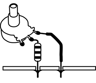
Figure 1 Potentiometer and fixed resistor in series.
To make the clock only go faster you connect the pot in parallel to the on-board resistor (essentially substituting it for your finger in the test we did in chapter 12): leave the resistor in place in the circuit, and solder wires from the two tabs of the pot to the two pads at the ends of the resistor (see figure 2).
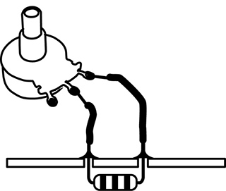
Figure 2 Potentiometer and fixed resistor in parallel.
To make the clock go slower and faster you remove the on-board resistor entirely and connect a pot of larger value than the removed resistor in its place (see figure 3).
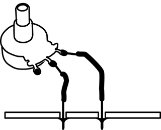
Figure 3 Potentiometer alone.
Finally, if you want the toy to go slower and faster but never crash, put the original resistor in series with the pot with clip leads (as in figure 14.1), then substitute progressively smaller resistors for your original value until you find one that lets the circuit run at the maximum speed without crashing, with the pot in the fully clockwise (i.e., 0Ω) position.
If all this doesn’t make sense in the abstract, check it out. Use the meter to measure some series and parallel combinations of fixed resistors. Then try some of these pot and resistor variations to a toy clock circuit until you feel comfortable with The Law.
Theory class is over.
Switches
How to Uunderstand Different Switches, and Even Make Your Own
You will need:
- An electronic toy or other sound-making circuit.
- Some hookup wire.
- A Single-Pole Double-Throw switch (SPDT), momentary or toggle.
- A plank of wood, some short nails, and a large ball bearing.
- Soldering iron, solder, and hand tools.
Switches are useful for turning power on and off to a circuit to save battery life, for turning on and off specific sounds or functions, and for resetting a circuit if it freezes up. They are often described in catalogs, on Web sites or in packaging by arcane abbreviations. Here are the main distinguishing features.
Mechanical Style
A switch can be momentary pushbutton, like a door bell, that changes state (turns something on) when you press it, and returns to its default state (off) when you release it; or it can be a push-on/push-off switch that alternates but holds its state. It can be a toggle switch with a lever, like a traditional light switch, that stays where you put it until you switch it back (usually). There is also the rotary switch, like the cycle selector on a clothes washer or the pickup selector switch on a Stratocaster, with which you choose between several positions, rather than just on and off. Slide switches, like the rotary switch, can select between two or more positions. There are a few other oddball switches we’ll discuss if they become relevant.
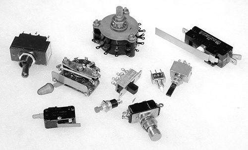
Figure 1 Assorted switches.
Number of Throws
A switch is also described by the number of mutually exclusive connections it makes when moved or “thrown.” A simple pushbutton that turns something on in one position, but does nothing in the other (beyond turning off), is called a “Single Throw” (ST) switch (see figure 2a). If the switch alternates between two possible connections, it is a “Double Throw” (DT) switch (see figure 2b)—this could be a pushbutton, a toggle, or a slide switch. Rotary switches that can make several different connections are classified by the number of connections, i.e., a five-position switch would be abbreviated as “5T” (see figure 2c).
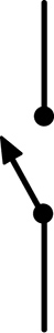
Figure 2a: Schematic representation of a Single Throw (ST) switch.

Figure 2b: Schematic representation of a Double Throw (DT) switch.
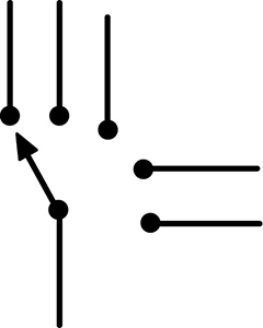
Figure 2c: Schematic representation of a Five Throw (5T) switch.
Number of Poles
Sometimes a single lever or button can switch two or more separate circuits simultaneously (think of the huge double-bladed switches in Frankenstein, thrown by one ominous handle). Most pushbutton and toggle switches are either “Single Pole” (SP; see figure 3a), meaning that they switch only one circuit, or “Double Pole” (DP; see figure 3b), which switches two circuits. The dotted line on the schematic representation indicates that the two sections switch in tandem. But switches can have three, four or more poles – they’re just less commonly encountered.
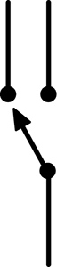
Figure 3a: Schematic representation of a Single Pole (SP) switch.
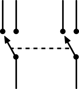
Figure 3b: Schematic representation of a Double Pole (DP) switch.
Terminal Designations
In a Double Throw switch the solder terminal that is normally off, or unconnected, is designated “Normally Open” (NO). The one that is normally on, or closed, is the “Normally Closed” (NC). The terminal that is connected, by the movement of the button or toggle, alternately to the NO or NC terminals is the “Common” (C; see figure 4).
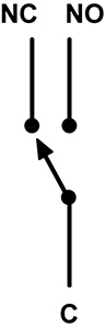
Figure 4 Switch terminal terminology: “NC” = Normally Closed, “NO” = Normally Open, “C” = Common.
Reset Switch
You may have noticed that a bent toy occasionally freezes up, usually when the clock is run too high or too low, or you short out some part of the circuit. As per the 12th Rule of Hacking, momentarily removing the batteries will usually fix the problem. But this gets tiresome. The problem is that most modern toys do not have mechanical on/off switches – like televisions, they are usually only asleep when you turn them off. Current is still flowing through parts of the circuit, and the toy – like your computer – will not truly reset without really powering down and back on.
We can add a reset switch that lets you press a button or throw a toggle to disconnect the batteries temporarily, without the bother of actually removing them. You’ll need a SPDT (Single Pole Double Throw) or DPDT (Double Pole Double Throw) switch. It can be a momentary switch, if the toy already has a built-in power on/off switch; if you want to use the reset switch as a power switch as well, then get a toggle switch instead.
Cut one of the two wires connecting the batteries to the circuit board. Solder one end of the cut wire to the switch’s Common terminal (C); solder the other end to the Normally Closed (NC) terminal. If the battery wire is very short you may want to extend one or both sections with some additional hookup wire. If the switch has more than three connectors, or they are unmarked, you should use a multimeter to figure out the switch logic.
With a momentary switch, the switch is normally closed, so the battery voltage flows into the C terminal and out through the NC terminal to the circuit; when you press the switch the C flips its connection to the NO terminal, breaking the connection to the NC terminal and disconnecting the batteries from your circuit. Next time your circuit crashes, return the clock speed pot to a middle setting, restore any other weird connections to their “safe” states, press the switch for a few seconds, and (hopefully) the circuit will “re-boot” when you release it—easier than removing the batteries, especially in front of a restless crowd at CBGBs or The Royal Albert Hall.
If you use a toggle switch the circuit will stay in the off state when switched, so it will function as a power on/off switch as well, saving battery life offstage.
Toggle or momentary switches can also be used to switch on and off any resistive jumpers you insert in a bent toy, to switch between a fixed clock resistor and a variable one (or between two different variables resistors – such as a pot and a photoresistor), to select between different output signals, etc.
Homemade Switches
Switches are useful, often essential, things. Unfortunately, they can also be the most expensive part of a hack: resistors, capacitors, wire, and many other electronic components you use in hacking typically cost fractions of a penny, but a switch can set you back a few dollars/euros. However, with a little mechanical ingenuity you can fabricate your own switches out of paperclips, springs, brass fasteners, and other scraps of metal—classic prison technology, like making a shiv from a bedspring. It’s more of a mechanical problem than an electronic one: find two pieces of metal that conduct electricity, then figure out a practical way to move them in and out of contact with one another.
Figure 5 A homemade tilt switch.
You can construct a nice multi-position tilt switch by hammering a ring of brads into a piece of wood, soldering a wire between each nail and a point on the circuit board that needs switching, and dropping a big ball bearing into the corral (see figure 5). You can use this switch to select different circuit jumpers in a bent toy, or switch between the outputs of several toys to feed the input of your amp. Variations on this design can be made with loops of wire, strips of copper, or even blobs of mercury (once a common switch element, now banished behind the sign of a skull and crossbones—see figure 6).
Figure 6 Some commercial tilt switches, using ball bearings and deadly blobs of mercury to connect contact points.
Jack, Batt, and Pack
Powering and Packaging Your Hacked Toy
You will need:
- A finished circuit or bent toy.
- A battery-powered mini-amplifier.
- Some hookup wire.
- One or more jacks for external audio connection.
- Some 1kΩ resistors.
- A battery holder (if appropriate—see text).
- A box of some kind to house your circuit.
- Soldering iron, solder, and hand tools.
In the midst of bending a toy or soldering a circuit it’s easy to lose sight of the light at the end of the tunnel: an artfully encased object that will elicit awe from your friends. Here’s some advice on getting the rat’s nest off the bench and into the real world.
Jacks
Beyond retuning the clock and finding some musically viable almost-shorts, the most significant change you can make to a bent toy is replacing the little speaker with a big one, thereby confirming the Second Law of the Avant-Garde (make it louder). A coil pickup resting on the little speaker is one approach, as discussed in chapter 6. But if your circuit is never going to be played by saliva-drenched fingers it’s safe to wire a connection directly to an amplifier – a bit more preparation work than slapping the coil down, but ultimately cheaper and faster to patch together in performance.
By adding a jack to connect the circuit to an external amp and a decent-size loudspeaker you not only make the sound much louder, which lets you hear more detail, but you will also hear low frequency components that aren’t audible through the tiny, parent friendly speakers inside most toys. And everyone wants more bass. It’s easy to do:
- Find the wires leading from the circuit board to the speaker.
- De-solder them from the speaker terminals or cut them as close to the speaker as possible.
- Solder these two wires to a female jack of your choice; usually it doesn’t matter which wire goes to which terminal, but you must always have one wire going to the shield/sleeve connector and one to the hot/tip connector.
- Plug into a decent sound system and listen. Start at a low volume setting, since the output can be surprisingly loud. If there’s lots of hum, reverse the hot and ground connection at the jack. If there’s no sound at all, check your soldering. You may find that the raw sound is too much—too noisy or abrasive, too much extreme high or low—but that’s where the equalization on a mixer, amp or graphic EQ “stomp box” can help you carve the sound you want out of your circuit’s raw material.
Let me repeat:
DO NOT ATTEMPT THIS MODIFICATION ON A CIRCUIT THAT WILL BE MAKING INTIMATE ELECTRICAL CONTACT WITH YOUR BODY (SUCH AS THE WET-FINGERS RADIO).
As long as you’re adding one jack, why don’t you see if there are any other interesting signals running around the circuit board yet unheard?
- Solder a wire from the shield/ground connection on a jack to the place on the circuit board where the “–” terminal of the battery connects, or to the shield/ground terminal on the main output jack, if you’ve added one already. Use stranded wire if at all possible – less strain on the connections at either end, and easier to pack into the toy’s case.
- Solder another wire to the hot tab of the jack and strip and tin the other end.
- Solder a 1kOhm resistor to the tinned end of this wire.
- Plug a cord between the jack and a battery powered amplifier.
- Turn the volume up just a little bit. Poke the free end of the resistor around the circuit board and listen to the different sounds (see figure 1). Adjust the volume as needed. Sometimes you can find very odd noises that seem completely unrelated to the basic sound of the circuit, especially with bent toys. Hold on to the body of the resistor, rather than the bare wire, to minimize hum.
Figure 1 Phil Archer hunting for interesting sounds. Photo © Phil Archer, used by permission.
- When you find a place you like, solder down the free end of the resistor. Wrap the bare wire and resistor lead in electrical tape to prevent shorts (you can shorten the resistor leads prior to soldering to minimize the amount of bare wire running around your circuit, itching for a short circuit.
- If you wish, add another jack and repeat the process, discovering and decanting hidden sounds. Or add a multi-position switch (like a rotary switch or our homemade tilt switch) to select among different circuit points to connect to a single jack.
If you get sound when one or the other of your jacks are connected to the amplifier/mixer, but not when you combine two or more, you have probably unintentionally crossed your grounds. De-solder one of the two incompatible jacks from its wires (the speaker jack, if used, is the first choice) and swap the “hot” and “ground” connections.
Cut-out Jacks
You may have noticed that most audio devices with a built-in speaker and a jack for headphones (such as a boombox) will switch off the speaker automatically when the headphone plug is inserted. This is accomplished with what is known as a “cut-out jack,” which basically combines the functions of an audio jack and a switch, and can be purchased at almost any retailer carrying electronic connectors. The jack’s terminals will be designated “tip” or “hot,” “sleeve” or “ground,” and “normally closed” (NC —like the switches we discussed in the previous chapter). These designations might be printed on the jack’s packaging, provided in the retailer’s catalog or web site, or you might have to decode them using your multimeter in the Ohms setting. You wire it as shown in figure 2.
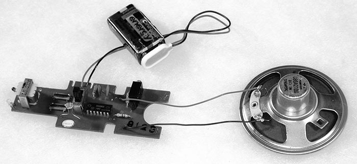
Figure 2 Wiring a cut-out jack.
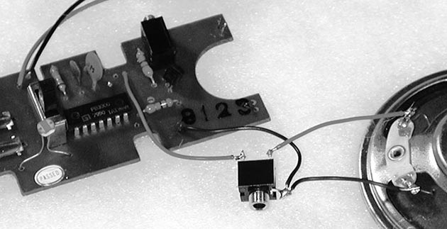
- Solder a wire between the jack’s ground lug and the circuit ground, in parallel to the speaker’s ground connection (do not disconnect the speaker ground); or you can cut the ground wire in the middle and solder both ends of the cut to the ground lug on the jack (as shown in figure 2).
- De-solder the wire from the speaker’s hot terminal and solder it instead to the jack’s tip/hot.
- Solder a new wire from the speaker’s hot terminal to the NC terminal on the jack.
Turn on the circuit. You should hear the sound through the built-in speaker as usual. Now plug a cord from the cut-out jack to your amplifier—the speaker should shut off while the signal passes to your amp through the patch cord. If not, check your wiring logic and soldering joints—it’s easy to make a mistake.
VERY IMPORTANT:
BE VERY CAREFUL CONNECTING A HACKED CIRCUIT TO A MIXER OR AMPLIFIER THAT GETS ITS POWER FROM THE WALL. IT’S BEST TO TEST FOR ANY POSSIBLE ELECTROCUTION HAZARD BY GINGERLY TAPPING THE CIRCUIT BOARD, JACKS, AND POTS WITH A DRY FINGER AND FEELING FOR ANY BUZZ OR TINGLE. ALTERNATIVELY, LET A SQUIRREL RUN ACROSS THE BOARD.
And always remember the 14th Rule of Hacking:
Rule #14: Kick me off if I stick (Zummo’s rule)
Always have a buddy nearby when there is a risk of electrocution, and chant Zummo’s mantra before you power up.
An excellent insurance against electrocution is to insert a DI box between your circuit and the AC-powered world – one of these can be purchased from retailers selling electric guitars, microphones, keyboards, etc. If you’re up for somewhat more advanced hacking, you can wire what is known as an “audio isolation transformer” between the circuit’s output and the rest of your sounds system (see figure 3). But if you are unsure of your hacks or the power grid, JUST STAY AWAY FROM ANY OUTLETS! Use a coil pickup on the speaker instead if you want to get loud.
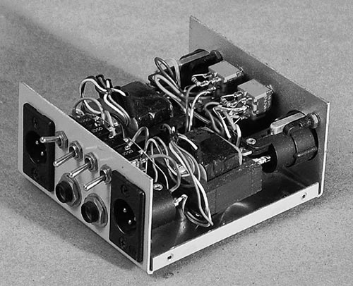
Figure 3 Homemade stereo isolation box made with output transformers removed from an API mixer, Nicolas Collins.
Battery Substitution
This section is primarily of value in circuit bending. Almost all toys use batteries that put out either 9 volts or 1.5 volts. Most 9-volt batteries look the same: bricks with two connectors that resemble android navels (one innie, one outie). 1.5-volt batteries come in a plethora of packages: cylindrical ones, like D cells (the biggest kind, in the flashlights wielded by Southern sheriffs), C cells (a little smaller), AA cells (“penlight” flashlight batteries), and AAA cells (even thinner and a bit shorter, like some metric mismatch of an AA battery), and button cells (the watch and camera batteries that are infernally small, come in a zillion different sizes and shapes, and are way too expensive and hard to find). A few button cells put out 3 volts (inside the casing are stacked 2 tiny batteries), and there are some oddball batteries (like the one that looks sort of like an AAA but puts out 12 volts, often used in remote controls for garage doors), but the vast majority of batteries follow the above rules.
Nine-volt batteries are usually used singly, but 1.5 volt ones are often combined to add up voltage to power a circuit—commonly found in sets of two, three, or four. The larger (and heavier) the battery the more current it provides, which means it lasts longer and can power a larger circuit, so:
Rule #15
You can always substitute a larger 1.5-volt battery for a smaller one, just make sure you use the same number of batteries, in the same configuration.
This means you can replace those little button battery cells with the same number of AA cells and run the circuit much longer and much cheaper, and afterwards you can find replacement batteries almost anywhere. All you need to do is:
- Disconnect the existing battery holder, noting which wire connects to the “+” end of the battery stack, and which connects to the “–” end (look at the labeling on the batteries or holder, or measure the voltage with a meter).
- Get a battery holder for larger batteries of your choice.
- Connect it to the circuit, observing the proper polarity of the wires you de-soldered earlier.
Some low-current 6-volt circuits (i.e., using four AA, AAA, or button cell batteries) will run on a 9-volt battery, and might even react to the additional juice with extra perkiness, but others will succumb to cardiac arrest. Unfortunately there’s really no way to know until you try it, so proceed with caution (and a duplicate circuit, if at all possible) and disconnect the new battery if you smell smoke or feel a component on the circuit board getting hot.
As you accumulate circuits you will be tempted to minimize your energy costs by using a single battery (or set of batteries) to run several devices. This, unfortunately, is notalways a good idea: sharing often induces noise, weird interference, and interaction, especially if you try to connect more than one of the circuits to the same amplifier.
Rule #16
It’s always safer to use separate batteries for separate circuits.
How big a battery to upgrade to has as much to do with fitting them inside the device as any electrical consideration, which brings us to our next topic.
Packaging
As your first hack nears completion you’ll want to think about how to package it. You have a few basic style choices:
Stealth: Keep the original packaging, with added knobs, switches, and jacks, as needed (see figure 4 and 5).
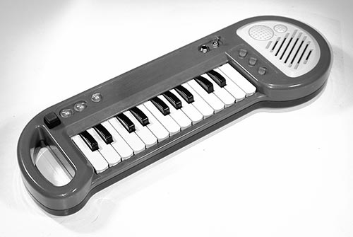
Figure 4 Stealth packaging: bent keyboard by Alex Inglizian.
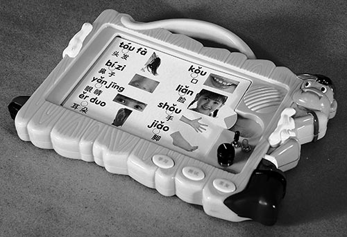
Figure 5 Stealth packaging: bent Chinese language trainer by Nicolas Collins.
Camp: Go for other recycled housing, such as a cigar box, a cereal box, or a human skull (see figure 6). David Tudor favored plastic soap boxes. After the rise of the DVD and streaming services, plastic VHS boxes filled the dumpsters outside rental shops and the attics of elderly relatives, and they make perfect homes for circuit boards (see figure 8). Cigar boxes are great because they can usually be had for free, and you can open them easily to change batteries or touch the circuit. If the clock speed is controlled by photoresistors inside the box, the pitch will glide up and down as you open and close the box, like a cubist trombone. Unfortunately, the wood of a cigar box is usally just a little too thick for most jacks and pots to mount easily—you may need to countersink the mounting holes in order to secure any nuts that screw down; alternatively, you can pass shielded cable through holes in the wood and solder plugs or jacks directly to the ends, and end up with a cigar box octopus. Altoid tins are good for small circuits (they hold a 9-volt battery neatly), but since they are made of metal you must make sure the circuit does not short out against the case – the discrete application of electrical tape to the bottom of the circuit board or the inside of the tin should do the trick (a sheet of thin cardboard works too); one can also buy plastic standoffs for this purpose. You can see Altoid tins in action throughout this book, the legacy of my son’s obsession with sweet breath.
Figure 6 Camp packaging: circuit inside Pringle tube by André Bosman.
Sandwich: Two slabs of acrylic plastic or thin wood with a circuit board in between (see figure 7). Fast to make, and clear plexi lets you see what’s going on inside.
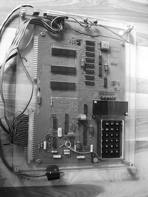
Figure 7 Vintage sandwich packaging: David Behrman’s “Kim 1” microcomputer, c. 1977. Photo © David Behrman, used by permission.
Traditional: One of those plastic or metal boxes that make your product look “professional” (or boringly geeky, depending on your perspective; see figure 8). Remember that a bare circuit board will short out if placed in a metal box unless it is isolated from the metal, as mentioned for the Altoid tin, above.
Figure 8 Traditional boring packaging: small amplifier by Nicolas Collins.
The decision is partly topological (how do I fit in the circuit, jacks, pots, and switches?), partly practical (what’s the easiest material to drill?), but largely aesthetic (what looks coolest?).
Now that your first hack is resting comfortably in a beautiful box, the time has come to show it off. Get out of the shop, pick up the phone and book that gig! Or at least upload something to YouTube.
Power Supplies
Carbon Footprints from AA to EEE
You will need:
- A DC wall-wart plug-in power supply.
- A diode, 1N4004 or equivalent.
- Some capacitors: 0.1, 100uf and as big as possible.
- A fixed-voltage positive regulator (LM7809 or LM7812).
- An LM317 variable voltage positive regulator
- Hand tools, test meter, and soldering iron.
- A breadboard on which to test your circuit.
- A solderable circuit board on which to assemble your circuit.
- Some solid and stranded hookup wire.
- A few solar cells
- Some fruits and vegetables
- Spare change, paper towel, salt, water
- A bicycle dynamo or small DC motor
Oh dear, I feel like a father enrolling his son in a driver education class or explaining safe sex: I wish we could stop here, but one day you will leave home and must be prepared for the big world.
Although the Second Rule of Hacking barred you from touching an AC power cord, the time will come when batteries simply will not suffice. You will tire of the cost of replacing them, and the accompanying environmental guilt (although these concerns can be minimized by rechargeable batteries), or you will build a circuit that draws so much current that it drains the battery flat before you can say “Union Carbide.” You will have to choose between living a long and virtuous (but possibly slightly constrained) life that adheres strictly to 25-fold path of the Rules of Hacking, or enjoying the risky heretic pleasures of power supplies. As a stopgap solution to exposing your hands and heart to lethal voltages, you can advance to the ubiquitous “wall-wart” that powers so many domestic appliances these days (see figure 1).
Figure 1 A typical wall-wart power supply.
The power grid in North America delivers to your outlet a sine wave that fluctuates between 0 and 120 volts 60 times per second; in Europe, 240 volts at 50 cycles per second, and in Japan 100 volts at 50 cycles. If you plugged a very strong speaker directly into the wall (not recommended, by the way), you would hear a loud, low pitch around 2 octaves below middle C. The wall-wart consists of a transformer encased in plastic and wired directly to an AC plug. The transformer takes the 100/120/240 volts of alternating current (AC) and steps it down to the nonlethal range suitable for powering electronic circuitry. The advantage of the wall-wart supply is that the dangerous voltages remain (in theory) within the plastic lump, and the ends of the wires present a mild, relatively safe, more battery-like voltage. The traditional power supply found inside your TV or guitar amplifier, on the other hand, brings the wall voltage right into the chassis, where it can easily be touched (ouch!) as you tinker. So, if you must use the electrical grid, let the wall-wart be your condom.
You can find wall-warts everywhere, often very cheap. Since the physical construction of the thing is an indication of the quality of workmanship inside, you are advised to select one that looks pretty solid, with no holes, cracks or wobbly parts (just keep my French Letter analogy in mind – without smirking, please).
There are two basic types of wall-wart. An AC wall-wart consists solely of a step-down transformer; it puts out a low voltage 60/50hz signal, which must be further conditioned to make it useful for powering circuitry. A DC wall-wart contains some additional circuitry (a few diodes and a big capacitor) required to smooth out the fluctuating signal into a voltage that more closely resembles the steady DC output of a battery.
The wall-wart should be marked with the following information:
- The primary voltage that the wall-wart can be plugged into, i.e., 120 (North America) or 240 (Europe) volts AC (VAC). Many modern wall-warts (such as those provided with most cell phones and laptop computers) handle any input voltage between 100 and 240 volts. Choose the appropriate primary voltage for the country in which you are working if you can’t find one with a “universal” prinary.
- The secondary voltage that appears at the loose end of the long dangling wire (or built-in jack), usually in the range of 3–24 volts. Some wall warts include a switch for selecting amongst different output voltages. We need a secondary voltage between 6–15 volts.
- Whether it has an AC or DC output. We need DC.
- The amount of power the transformer can provide, usually measured in watts (W), amps (A or MA), or volt-amps (VA). We want a transformer that puts out a minimum of 100 milliamps (ma), which may be indicated as 0.1 amps or 5–10 watts.
For example, a wall-wart might be labeled “120vac input, 12vdc output, 200 ma.”
Built into the plastic casing should be a power plug appropriate to the outlets in your country. In some instances the wall wart is more like a rug rat, with a power cord instead of a built-in plug; sometime this cord is attached to the plastic lump, and sometimes it plugs into a socket of some sort. If there’s no output jack, two wires should emerge from the other side of the wart: they may be a parallel pair, like speaker cable or lightweight lamp cord, or may be shielded cable, with one conductor wrapped around the other. At the end of this cord will be one of a zillion different types of minimally distinguishable little plugs – usually some form of tortiglioni-like “coaxial power connector”. Some cables terminate in a system of interchangeable connectors of different style.It’s convenient if the plug matches some loose female jack you have in your parts collection, or one you can buy locally. It’s risky to buy one part or the other sight unseen: never trust measurements on packaging, always test that the male and female connectors fit together snugly. On the other hand, matching connectors are not essential: you can always cut off the plug and connect the bare wires directly to your circuit, or solder on a new plug from a matching plug and jack set you acquire elsewhere.
When adapting a battery-powered circuit to be powered by a wall-wart you must observe two critical factors:
- The wall wart’s voltage must be within the two limits we described above (i.e., greater than 6 volts but less than 15 volts), but the current capability can be anything higher than the minimum need to power the circuit. For example, a circuit requiring 20 ma can be powered by a supply producing 20 ma, 100 ma, or 1000 ma. The circuit will only draw as much current as it needs (sort of like having an oversized gas tank in a car you only use to go shopping around the corner.)
- Check the polarity of the secondary connector or wires: you must know which is “+” and which is “–” before connecting the wall-wart to your circuit, or catastrophic pyrotechnics may result.
Sometimes the wall-wart will be marked with information specifying which part of the connector is “+” and which is “–”. Sometimes one of the cables will have a convenient white stripe that distinguishes it from its mate. But it is always safer to confirm the polarity with a multimeter.
Set the meter to measure “DC Voltage.” One probe plugs into the meter’s “ground” or “-” input, while the other connects to something probably marked “voltage” in red. Touch one probe to one part of the connector, and the other to the other; if you’ve already removed the connector measure between the ends of the stripped wires. If the meter reads out a voltage with no prefix (i.e., “13.6”), then the wire/connector touching the ground probe is the “–” output, and the other is the “+.” But if the meter puts a “–” before the number (i.e., “– 13.6”), you know that the connections are reversed, that the wire touching the minus probe of the meter is actually the “+” output and the other is “–.” Confused? Try this test on a nice familiar (and safe) 9-volt battery. Then test the wall-wart again.
Once you figure out which wire is which, mark them carefully: scribble a drawing of the connector with appropriate + and – markings, or wrap some colorful tape around one wire. If the output voltage of your wall-wart measures less that 15 volts DC you can connect it more-or-less directly to your circuit. You can either use the matching connector to whatever plug is attached to the wall-wart’s cord, or you can cut off the plug and solder the wires directly to the board. Double-check the polarity before you plug it in!
Cheap wall-warts will usually have some “AC ripple” in their voltage output—a sign of skimping on parts in the conversion from AC to DC (you usually don’t get what you don’t pay for, I’m afraid). A circuit powered with such a supply may hum – under its breath or quite loudly, depending on the quality of the wart. If you alternate between a battery and wall-wart powering the same circuit you should be able to hear the difference. Until you get good at designing or choosing better power supplies, a battery will usually sound cleaner. One easy fix that usually helps is to add a big capacitor, say between 100–10,000uF, between “+” and “–” supply on your circuit board. As mentioned in chapter 18, big electrolytic capacitors have polarity, like a battery, which is marked on the body. Make sure you connect “–” to the ground bus, “+” to “+” supply. Placing an additional 0.1uF capacitor between the “+” and ground supply pins very near each chip also helps lower noise and reduce “crosstalk” between different parts of your circuit. Both these capacitors can be seen in figure 2.
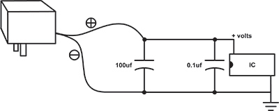
Figure 2 Basic filtered power supply
A quick measurement with a meter will show that even though a wall-wart might be marked “12 volts DC” in bright white letters, it could put out anything from 10 to 20 volts. The CMOS chips used in most of our circuits were chosen in part for their forgiving nature, but they have their limits—upper limits: they can run on power supplies from 3 volts to about 18 volts, but above 18 volts they can expire quite dramatically. A 9-volt battery sits comfortably between these two extremes. If you choose to use a wall-wart instead of a battery always measure its actual output voltage and polarity before connecting your circuit—don’t rely on the markings on its case.
Rule #25: Never trust the writing on the wall-wart.
Alternatively, for a really quiet, reliable supply you can add a simple integrated circuit called a “voltage regulator” (see figure 3). A regulator filters out the last of the AC ripple and sets the voltage to a precise level, which is specified by the last two digits of the chip’s part number: 7812 = 12 volts, 7809 = 9 volts, 7805 = 5 volts, etc.
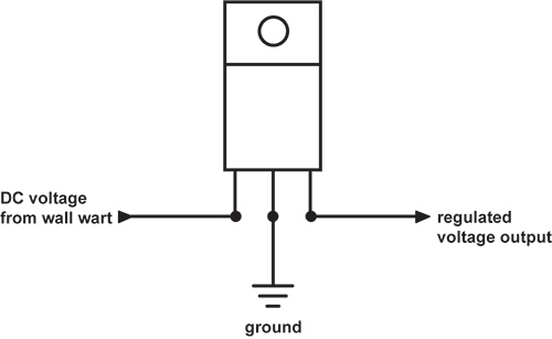
Figure 3 78XX-series voltage regulator pinout.
The input to the regulator must be at least 3 volts higher than it is expected to put out (i.e., 12 volts in for 9 volts out), and no higher than about 25 volts; so measure the output of your wall-wart with your meter to make sure it is within these limits. You can get regulators for a wide range of output voltages – the 7809 is a shoe-in for the 9-volt batteries we’ve been using, but the 7812 and 7805 are more commonly encountered, and our CMOS chips should run fine on any of these three. The basic design shown in figure 4 works for any 78XX series regulator. It’s normal for the regulator to get a bit hot—bolt the regulator’s tab to a piece of metal to dissipate the heat (or you can buy yourself a fancy finned heat sink).
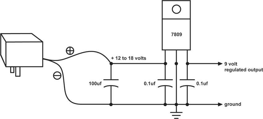
Figure 4 A simple regulated power supply.
If you have had success with the voltage starve-circuit we described in chapter 15 (figure 15.13) you can implement it with a wall-wart, with or without regulator, feeding the pot just the same as a battery. Or you can build a power supply whose output voltage can be adjusted quite precisely, using a slightly different regulator, the LM317T see (pinout in figure 5). The potentiometer in the circuit shown in figure 6 lets you adjust the voltage anywhere between about 1.2 volts and almost the voltage coming out of the wall-wart. The LM317 looks the similar to the 78XX regulators, with three legs, but the connections to the pins are different, so double-check your wiring before plugging in the wall-wart.
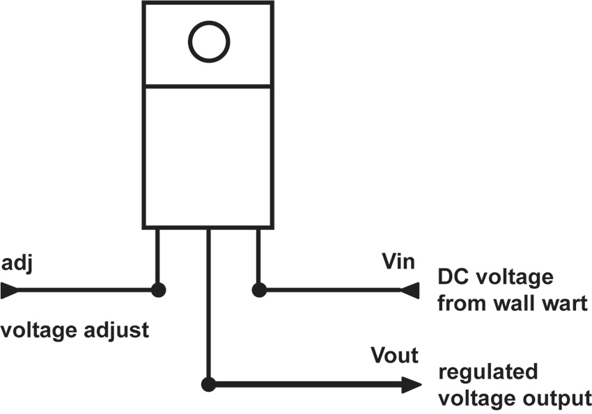
Figure 5 LM317 Voltage Regulator pinout
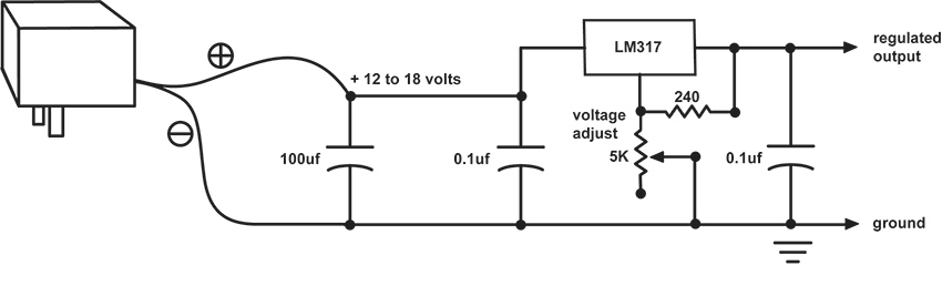
Figure 6 Variable voltage power supply with LM317
Going Green
If you feel like kicking your Duracell habit, but also want to stay off the grid, consider some alternative power suggestions that will reduce your carbon footprint to smaller than the business end of a stiletto heel. The obvious first step, as I suggested way back in chapter 1, is to invest in some rechargeable batteries in lieu of the disposable kind. The newer NiMH (Nickel-Metal Hydride) batteries are much more efficient than any alkaline cell, packing more current (i.e., run time of your circuit) into a lighter package. They are available in many configurations, from AAA to D, as well as 9-volt. You can charge them quickly in any AC outlet, or invest in a solar charging unit.
Speaking of solar, there’s no reason – aside from cloud coverage – that you can’t power your circuits directly off old Sol. Solar power panels are abundant these days, and they are decreasing in price as they increase in power. You can sometimes buy one that substitutes directly for a battery or wall-wart, providing 5-12 volts at 500 milliamps or more of current (check out marine supply stores). But they can be a bit pricey. A more economical (and educational) alternative is to seek out – usually on-line -- the individual cells that make up these panels. The cells are rated for voltage and current output. They have a pretty low output voltage – usually around 1.5 volts – but come in a wide range of current ratings, typically a function of the size (see figure 7). Sometimes the cells are combined to add up to higher voltage. Pick a model whose current is sufficient for your circuit needs – 100 milliamps (ma) is sufficient for most of our circuits, 500ma if you’re powering a small amplifier, like the LM386 from chapter 24, as well. Then buy enough to add up the voltage you need for you circuit. Bearing in mind that the CMOS circuits we’ve been powering on a 9-volt battery can run on voltages as low as 3 volts, you may be able to get away with only a handful of cells (see figure 8).
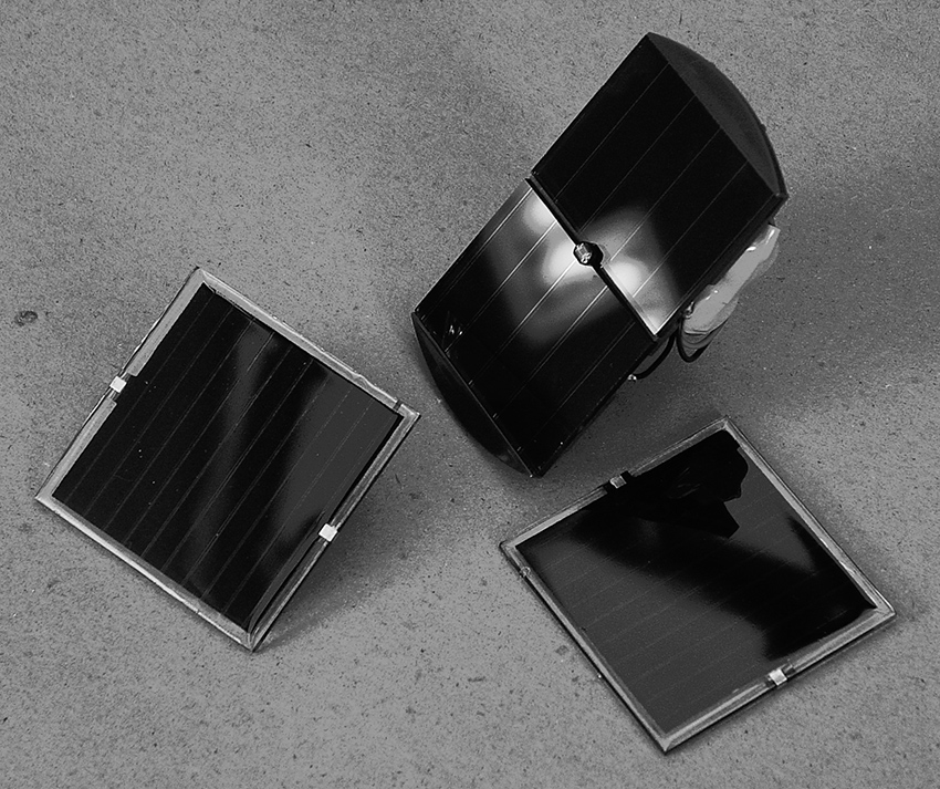
Figure 7 Assorted solar panels (center unit with rechargeable batteries attached)
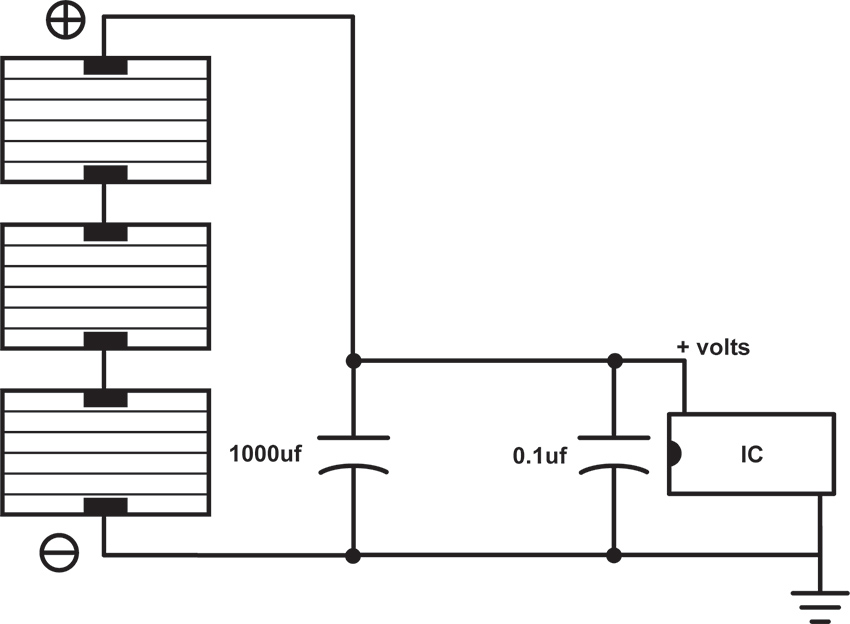
Figure 8 Direct solar power of a circuit by adding voltage output from multiple solar cells
A critical component in figure 8 is the capacitor. Remember how, in chapter 13, I compared the capacitor to a bucket? In this circuit the capacitor is your canteen in the desert, tiding you over between oases (or a cistern collecting rainwater so you can continue to shower after the storm has passed). The capacitor acts a little bit like a rechargeable battery whose strength is proportional to its size in uf. Without it the circuit responds directly to the amount of light present: when the sun shines the circuit runs; when a cloud passes the circuit shuts off. If we insert a medium size capacitor, say 1000uf, it will retain enough energy to bridge the gap caused by a scudding cloud, but not enough to keep it running overnight. If we get an insanely large capacitor, say around 1 farad (not micro-farad), such as are used in memory backup applications, it holds the charge much longer, acting much more like a rechargeable battery. Finally, we can substitute actual rechargeable batteries (usually a set 1.5-volt cells stacked to add up to your desired voltage) for the capacitor, and modify our design slightly, as shown in figure 9. At this point whatever we hang off this circuit is really being powered by the battery, not the sun, and the battery is in turn being “trickle charged” by the sun, weather permitting. Be sure that the series voltage of your photocells is greater than the battery voltage, or the batteries won’t charge, and less than the maximum voltage for the circuit (i.e., 15 volts), or the chip might fry.
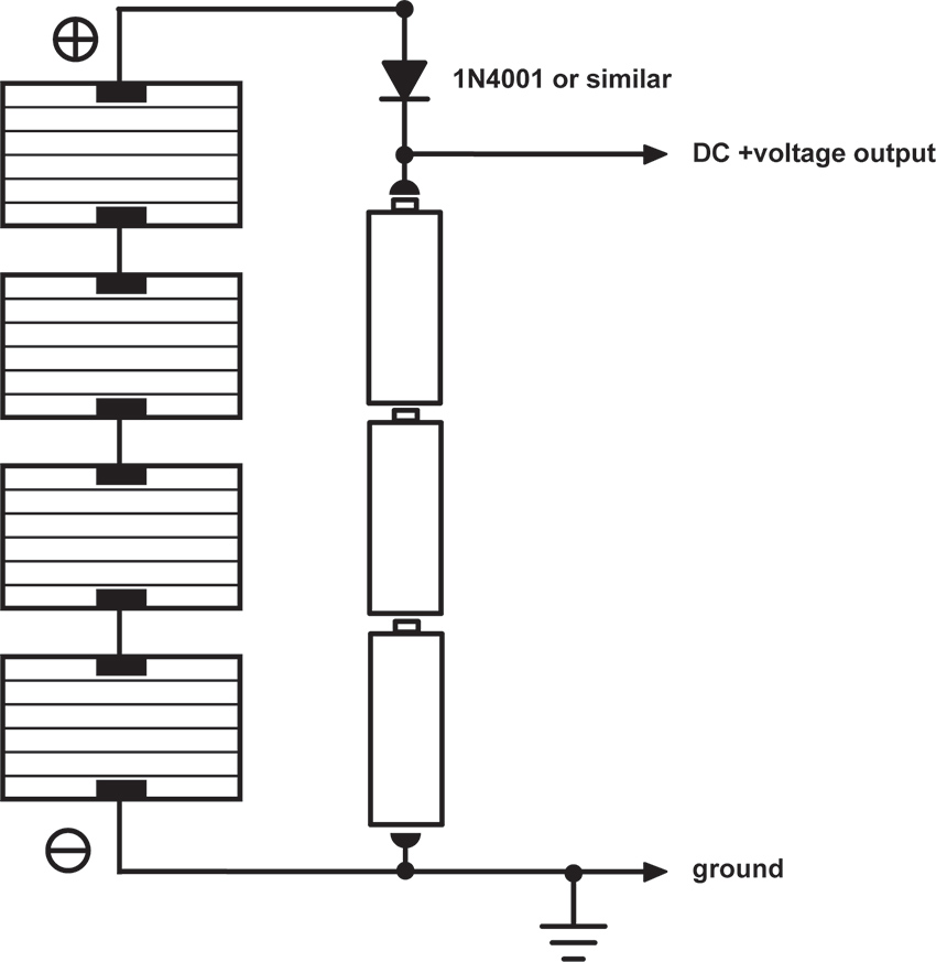
Figure 9 Solar-powered battery charging circuit
As on a few other occasions in this book, I should explain that figure 9 is a simplified design. Proper battery chargers can get quite complex -- these days many incorporate microprocessors that regulate the charging current and monitor the cell’s condition to minimize the charge time and maximize the battery’s lifetime. If you are serious about the long-term survival and performance of your project you should consider either springing for a commercially available solar-powered battery charger, or type those key words into Google and spend a few minutes downloading schematics by people who know more about this arcania than I do.
My First Bio-fuel
The older among you, with dim memories of grade school science fair projects with potatoes and nails, might be wondering about the possibility of building your own battery with the contents of your crisper bin. Not only can it be done, but with proper lobbying you might convince Congress to subsidize your efforts to free American electronic music from the shackles of oil and coal.1
The potato battery functions on the same basic chemical principle as a traditional battery: when two strips of different metals (typically copper and zinc) are inserted into an acid solution (in this case the liquid in the potato’s cells) an electrochemical reaction takes place, which generates a potential difference between the metal strips. A pair of electrodes (as the metal strips are called) inserted into a potato will generate around 1 volt at a very small current. Individual bio-cells can then be added in series and parallel to produce higher voltages and more current.
A copper penny or strip of copper wire can serve as your positive electrode, and a galvanized nail for the negative one. Insert them into a potato, lemon, or apple, and measure the voltage with a multimeter. Put several electrode pairs in series as shown in figure 10 -- you can use a separate vegetable or fruit for each pair, or insert multiple electrodes in a single large tubor. Make sure none of the electrodes touch each other. A quick check with the meter should confirm that your power station is putting out around one volt per potato. You can connect an LED and, if the orientation is right, it should light up. Hook up your new battery to a simple oscillator circuit and see if it runs. If it doesn’t you might need to add a few more potatoes in series to increase the voltage, or in parallel if your circuit requires more current.
Figure 10 Adding multiple potato cells in series to increase voltage
The voltage output of this kind of battery is a function of the metals used for the electrodes, rather than your choice of produce: copper and zinc (present in galvanized hardware) yield about 1.1 volts per cell. Substituting magnesium for the zinc increases this to about 1.6 volts (I’m not sure what the most convenient source of magnesium scrap would be). The lifetime of your battery is primarily a function of how long it retains its moisture, so you might experiment with more succulent options, such as lemons, grapefruit, etc. And do bear in mind that these earthy batteries put out a very small amount of current – if you’re lucky our low-power CMOS oscillators will whistle comfortably on potato juice, but don’t expect to run an amplifier or motor this way.
In chapter 13 we discussed using bits of vegetables and fruits as alternative resistors in toy clocks and oscillators. The resistive character of these materials is primarily a function of their moisture content, although we can speculate now that their electrolytic interaction with the wires we used to make the connections might also influence the behavior of our circuits: two wires of the same metal (i.e., copper) should not induce voltage, but different metals can. You might experiment with the contents of your garden for both a power supply and a timing component in your circuits. Too bad we can’t grow our own chips…. (David Tudor once told me a story of a Brazilian electronic music composer who, in the early 1960s, was making his own transistors by baking crystals in his oven but, sadly, I was not able to follow up this lead before Tudor passed away.)
One last observation: the voltage output of these bio-batteries is not as steady as your basic Duracell. In fact, the chemical process at play generates a fair amount of noise – a capacitor added to our power supply circuit should smooth this out if it’s problematical. On the other hand, if instead of connecting the electrodes to a circuit or LED you wire them to the tip and sleeve of your headphones, you can listen directly to the crackly sound of a singing potato. Not loud enough? Connect to electrodes to the input or your amp or mixer, and turn it up.
Kitchen Sink
As long as you’re rummaging about in your refrigerator for fruit and vegetables, you might scan your kitchen for some paper towel and salt. As Cy Tymony has shown in his wonderful book, Sneaky Uses For Everyday Things, you can build potato-like batteries from nothing more than spare change, wet paper towel, and table salt. Each cell requires one penny and one nickel, for the copper and zinc electrodes respectively (sorry, Euro-toting hackers, you’re out of luck). You can solder a wire to each. Fold a piece of paper towel into a coin-sized pad, dampen it, sprinkle it with salt, and sandwich it between your coins. Measure the voltage between the two electrodes and it should be in the potato range. The clever thing about this style of homemade battery is that you can just stack your change in a folded strip of paper towel to build up whatever voltage you want, rather than digging up a fresh spud for every volt. Wire cells in parallel to increase the current capacity.
Hand Jobs
For the ultimate in self-sufficiency consider combining alternative energy resources with a physical fitness regimen. A generator is a device convert repetitive mechanical motion into electricity. Most function electromagnetically, and bear the same relationship to an electric motor as a microphone has to a speaker: spinning a shaft rotates a coil in a field of fixed magnets, inducing a current flow (remember using a motor to generate sounds in chapter 4?). Traditional power plants use coal-, oil-, or gas-powered turbines to spin these generators; hydroelectric dams channel water past turbine blades; wind farms are popping up all over. Older Dutch hackers will immediately think of the whirring little dynamo on the front wheel that powered pre-LED bicycle headlights – these can easily be adapted to stationary exercise bikes, skateboards, egg beaters, spinning wheels, fishing reels, water wheels, windmills, steam engines, etc. Whether a response to soaring energy prices, or merely a green affectation, generators are showing up in a number of common consumer products: flashlights that light when you squeeze or shake them, radios and laptops with hand-cranks, etc. The generator element can be removed from any of these devices and re-wired to power your circuit.
As you might infer from the interchangeability of speakers and microphones, any DC motor can be used as a generator: connect the motor terminals to an LED, spin the shaft, and see the light (see figure 11).
Figure 11 Motor-as-generator: spin the shaft and watch the LED light
As with our solar circuits, the critical factor is smoothing the erratic output of the generator so that the circuit doesn’t shut down when you park the bike, or the wind dies down. The solutions are basically the same as those shown elsewhere in this chapter: add a big capacitor, or configure the generator as a charger for a rechargeable battery. Then again, of you had interesting results from the voltage starve circuit you may find that a relatively unfiltered generator makes a good “performable power supply”. Ithai Benjamin’s and Alejandro Abreu’s “Synthinetic” (see figure 12 and their video on the website) and Phil Archer’s “Music Boxes” (see his video on the website) are lovely examples of this type of power supply in action.
Figure 12 “Synthinetic” by Ithai Benjamin and Alejandro Abreu, using motor as generator. Photo © Ithai Benjamin and Alejandro Abreu, used by permission
1 Written before the rise of the Trump regime, preserved out of naïve hope for a better future, eventually.
Circuit Bending
Tickle the Clock
Finding the Clock Circuit in Toys
You will need:
- An electronic noise-making toy.
- Small screwdrivers.
- A fine-tip permanent marker.
- Optional: two test leads with alligator clips and a resistor in the range of 1kOhm – 4kOhm.
Hacking is a lot like hot-rodding your car: you don’t need to be able to build a car from scratch to swap in a 4-barrel carburetor, but it helps to know what a carburetor looks like before you get too creative with the wrench. We’ll use a simple but useful hack as a step toward identifying basic electronic components, and introduce some electronic axioms along the way.
How to Choose a Toy
As with the radio in our “laying of hands” experiments (chapter 12), select a toy that is expendable, not too tiny, and has a built-in speaker. A toy that makes sound is preferable to a mute one, and sampled sounds (like voices, animal sounds, or instruments) are more rewarding than simple beeps. The more buttons and switches the better, generally speaking. Keyboards are a gamble: some cheap Yamahas hack magnificently (the PSS-140 is especially satisfying), while others have curiously limited potential for interesting modification. Cheaper is better, especially for our first experiments—the more expensive toys, and almost all that put out video, often use crystal clocks, which are more difficult to hack (these include sophisticated handheld games such as Gameboys, robot toys such as Furbies, and more sophisticated music keyboards). However, since the start of the new millennium there has also been an increase in the number of super-cheap toys coming from China that are really impossible to hack (this will be explained), so beware. To the degree that one can distinguish such detail when trawling through thrift shops, toys from the 1990s hack more easily than more recent ones, and usually have a richer sound palette than most from the 1980s (with a few notable exceptions: the venerable “Speak and Spell”, introduced in 1978, is worshipped by circuit benders).
And: THE TOY MUST BE BATTERY POWERED!
Clocks
The majority of electronic toys manufactured since the early 1990s are essentially simple computers dedicated to running one program. In most, a crude clock circuit determines the pitch of the sounds and the speed of its blinking lights, graphics and/or program sequence.If you can locate the clock circuit and substitute one component, you can transform a monotonous bauble into an economical source of surprisingly malleable sound material.
What’s Under the Hood?
Open up the toy, carefully noting wire connections in case one breaks. Keep the batteries connected, as we did with the radio in chapter 12 (similarly, this might require some ingenuity, clip leads and electrical tape). Expose both sides of the circuit board.
Study the board and try to identify the following types of components:
- Resistors: little cylinders encircled by colorful 1960s retro stripes (see figure 1).
- Capacitors, in two basic forms (see figure 2):
- small discs of dull earth tones, or colorful squares;
- cylinders, upright or on their side, fatter than resistors, with one stripe at most.
- Transistors: three wire legs supporting a small black plastic blob or metal can (see figure 3).
- Diodes: glass or plastic cylinders, smaller and less colorful than resistors, usually marked with one stripe (see figure 4).
- Integrated Circuits (ICs): usually black or grey, resembling rectangular bugs with legs along one or more sides, or malignant looking black circular blobs oozing up from the circuit board (see figure 5).
- LEDs (Light Emitting Diodes): colorful sources of light (see figure 6).
- Other things you’ll learn about later.
Figure 1 Some resistors.
Figure 2 Some capacitors.
Figure 3 Some transistors.
Figure 4 Some diodes.
Figure 5a Some Integrated Circuits.
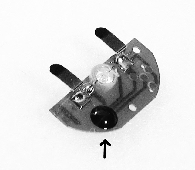
Figure 5b Some Integrated Circuits.
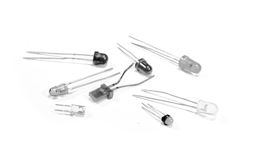
Figure 6 Some LEDs.
Most contemporary toys (as well as other electronic devics) are being made with “surface mount devices” (SMDs)— insanely tiny, rectangular versions of the above building blocks (see figure 7). Until you gain some hands-on experience with them you can despair of distinguishing the various different types of components, and decoding and hacking these toys will be a doubly foggy experience. If you have a choice, start your experiments on a toy with the larger, more traditional and more easily identifiable components described above (another reason to scavenge an older, used toy in a thrift shop, rather than buy something new at the mall).
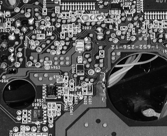
Figure 7 Circuit board with disturbingly small surface mount components.
We’re looking for resistors, especially those lying near an IC, flanked by a disc or square capacitor. The frequency of the simple, easily-hackable clocks in most toys is controlled by a resistor and a capacitor working together (explanation follows – be patient). If the circuit board appears to have one shiny black blob and not a single resistor, you may be holding one of the unhackable new Chinese toys: the clock is hidden inside that blob, where you can’t get at it, so you might as well hand the toy on to a grateful child and return to the thrift shop.
Laying of Hands, Again
As with the radio experiment we did in chapter 12, your fingers are usually the most direct form of circuit manipulation and testing. Get the circuit making sound. Position it so that you can touch the solder-side of the circuit board, if possible while looking at the component side. Lick one fingertip and place it across various solder pads; in particular try to connect across points at either end of a resistor, so that your finger parallels the resistor’s connection (see figure 8). When your finger bridges a resistor that is part of the clock circuit you should hear the pitch slide up a bit, or the tempo speed up. If the circuit has lots of connections, and you are having trouble finding the spot, concentrate on those resistors lying close by small capacitors, usually near the biggest IC on the board. If the circuit is too small for your fingers, clip a test lead to each end of a resistor in the range of 1–4kOhm, and touch the free ends of the leads to the ends of various resistors on the circuit board until you hear the pitch go up.
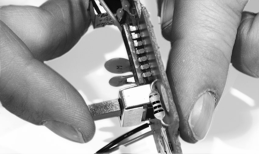
Figure 8 Finding the clock resistor (finger on right).
When you think you’ve found a hot spot, mark it on the circuit board with a Sharpie.
If the circuit incorporates the above-mentioned SMDs, most of the components and connections will be on the same side of the board, and it may be difficult to distinguish the capacitors from resistors. Sometimes resistors are identified by the letter “r” followed by a number, in a miniscule font, either on the component itself or (more likely) immediately adjacent to it on the circuit board; likewise capacitors are sometimes labeled with a “c” plus a number. Go after the blips with two shiny solder blobs at either end, rather than three or more, and you’re more likely to hit one of the timing components (your pinky may prove a more suitable tool than your index finger). Good luck—it can be very frustrating, and at a certain point you may want to give up, go out, and find yourself another (older) toy with bigger, more recognizable components.
If you have no success finding the spot, the toy might be one of the new, super cheap Chinese models described above. Or it may use a crystal for the clock timing, rather than a simple circuit with a resistor and capacitor (as mentioned earlier, this is especially true for more advanced musical keyboards, toys with video output, and complex or expensive toys). Crystals often take the form of a small shiny metal cylinder or a three-legged epoxy-dipped blob, usually brightly colored. If you suspect a crystal is at work you’d best put the toy aside and try another. On the other hand, sometimes you’ll get lucky and won’t even need to lay a finger on the circuit board to find the clock resistor: some toys, such as the “Microjammer” guitars, include a pitch control knob or slider.
What’s Happening?
Electric current flows through wire like water through a fat pipe. Resistors are like skinny pipes, or the rust-laden risers of NYC loft buildings: the higher the resistance (measured in chantworthy Ohms), the less current flows. Capacitors also resist the flow of electric current, but resist it more at some frequencies than others, in a manner that defies a simple liquid analogy. Capacitance is measured in soukable Farads, usually in small enough amounts to be called “microfarads” or “picofarads.” (Yes, the vocabulary of hardware is much cuter than that of software.)
Many oscillator designs rely on feedback: a speaker feeding back into a microphone is essentially an oscillator; when your damp finger bridges the right contacts on a radio circuit it produces feedback around an amplifier stage and sets the circuit oscillating. A clock circuit, whether in a cheap toy or an expensive computer, is just an oscillator, designed to run at a specific, carefully chosen frequency. In the simple clock circuit used in most toys a resistor and a capacitor are built into the feedback loop of a kind of an amplifier. With enough gain this circuit starts to feed back, just like a mike and speaker, at a frequency determined by the values of the resistor and capacitor. Make the resistor or capacitor smaller and the frequency goes up; make either larger and the frequency goes down. When the frequency gets too high to hear, it enters the range of a useful clock rate for a computer or a digital toy (or a way to summon your dog).
When you place one resistor in parallel with another you lower the overall resistance (think of it as adding an additional pipe for the current to flow through – see “Ohm’s Law” in the Technical Bootcamp section of this website).) Your skin is a resistor, as we demonstrated in chapter 12); when you press your finger across the circuit board contacts you effectively add a second pipe to the resistor on the other side of the board, decreasing the net resistance. More current flows and the pitch goes higher.
If the explanation is confusing, don’t worry about it. For better or for worse, we’ll revisit the secret lives of resistors and capacitors in a more clinical fashion when we get to building our own oscillators in Chapter 13. Until then just let your fingers do the thinking (and watch Video 13, “Hack The Clock”, in the Tutorials section of the website).
Got it? Good. But what do we do if we want to make the pitch lower? Read on….
Hack the Clock
Changing the Clock Speed for Cool New Noises
You will need:
- The sound-making electronic toy.
- Some hookup wire, stranded and solid, 22-24 gauge.
- Test leads with alligator clips.
- A few resistors of different values.
- A potentiometer, 1MΩ or greater in value.
- Soldering iron, solder, and hand tools.
Wet fingers are fine for making the clock go faster. But we all know that the Third Law of the Avant-Garde states:
Slow it down, a lot.
To slow it down we need to make the resistance larger instead of smaller. Which means removing the clock resistor from the circuit board (once you are sure which one it is) and replacing it with a larger one, instead of bridging it with your finger as we did in the last chapter which, by lowering the resistance, can only make the pitch go up.
- Locate the clock resistor you identified in the previous experiment (“Tickle the Clock”). Wedge a small flat-bladed screwdriver under it. Melt the solder on the underside of the circuit board at one end of the resistor, and lever the screwdriver to lift that end free from the solder connection (see figure 1). Do this quickly but gently, so as not to damage the circuit board or components. Now grip the resistor with a pair of pliers and pull it free of the board as you melt the other solder joint. Put it somewhere safe and don’t lose it! If the circuit already has a pitch-control potentiometer (“pot”), de-solder and remove it entirely.
- Strip and tin the ends of two short pieces of hookup wire. Press the end of one into one of the holes left after removing the resistor from the component side of the circuit board. It’s easier to do this with solid hookup wire, but in the long term it’s better if you use thin stranded wire for this, so you might want to give it a try (twist the stranded wire before tinning and it will be more likely to pass neatly into the hole). Melt the solder on the solder side of the board as you press the end of the wire through the hole. Touch up the solder joint with a bit of fresh solder to make sure it is solid, but avoid excess solder “bridging” the gap between traces that are supposed to be separate. Repeat with the second wire into the other hole. Your circuit board should now have two colorful whiskers sprouting from among the other, vertically challenged components (see figure 2). If you removed a pot from the board, there may be more than two holes; solder a wire to each of them. If you have problems fitting the wires through the holes you may have to clear out the old solder first – the best tool for this is the eerily cosmetological-looking “solder sucker” (see figure 11 in “Analog to Digital Conversion” on this website), but an artfully wielded straight pin can work too.
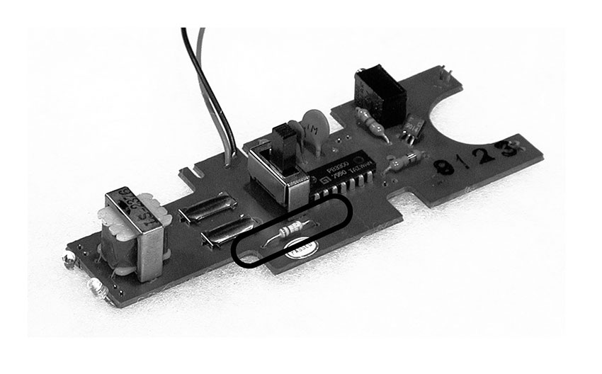
Figure 1 Removing a resistor.
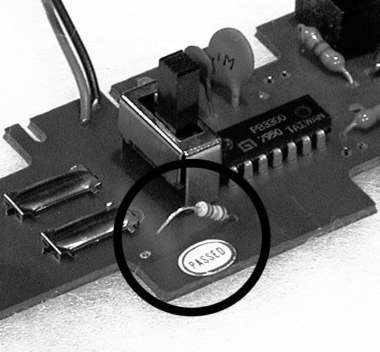
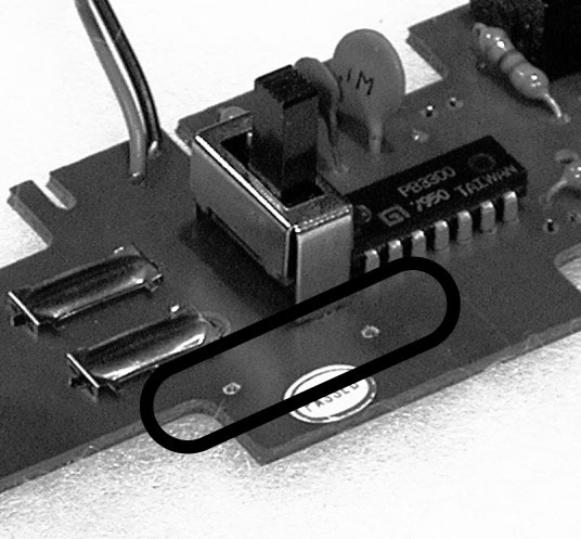
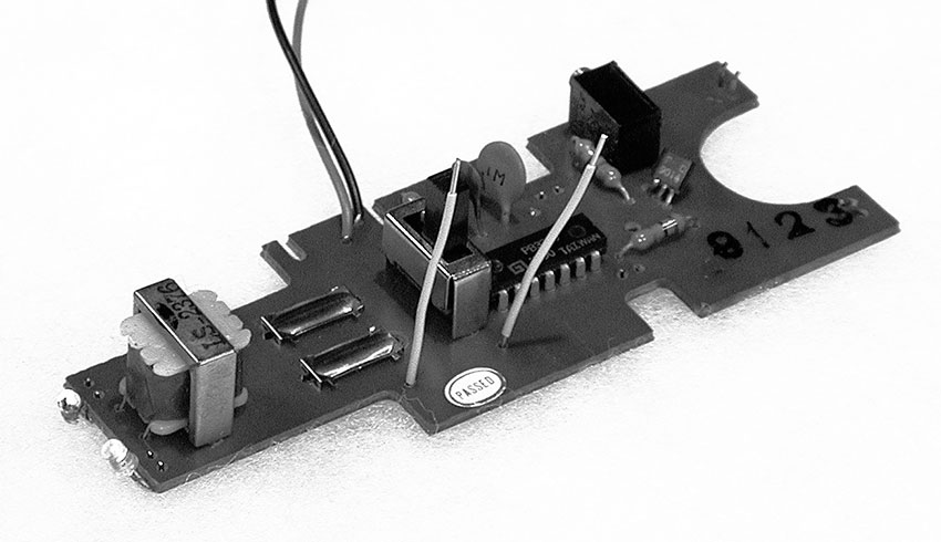
Figure 2 Resistor whiskers.
The copper traces on printed circuit boards can be very delicate, and the twisting of the wires as you go through the following experiments can tear the trace, sometimes irreparably. Which is why greater flexibility of stranded wire offsets the difficulty of forcing it though the holes. It is also a good idea to provide some kind of strain-relief for your whiskers. The easiest method is to bend them gently so they lie flat against the board, and then tape them down with electrical tape to prevent them from moving at the point they pass through the board (see figure 3).
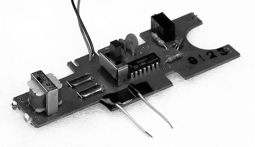
Figure 3 Whisker strain-relief.
- Attach a clip lead to the free end of each of the wires. Clip the resistor you removed between the other ends of the clip leads, effectively re-inserting it to the circuit (see figure 4). If you didn’t damage anything in de-soldering, the circuit should behave as it did before the operation. If it doesn’t, you may need to “restart” the toy by removing and reinstalling the batteries (see Rule #12, below).
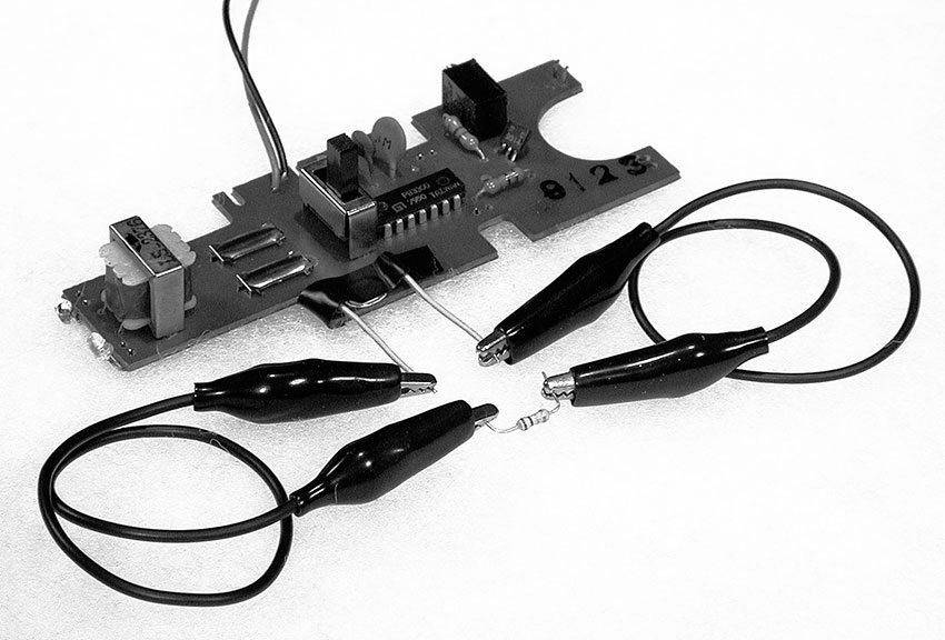
Figure 4 A remote resistor.
- Those colorful stripes around the resistor indicate its value. Look at the decoder chart in figure 5 below:
| Color | Value | Multiplier |
|---|---|---|
| Black | 0 | 1 |
| Brown | 1 | 10 |
| Red | 2 | 100 |
| Orange | 3 | 1,000 |
| Yellow | 4 | 10,000 |
| Green | 5 | 100,000 |
| Blue | 6 | 1,000,000 |
| Violet | 7 | 10,000,000 |
| Gray | 8 | 100,000,000 |
| White | 9 | 1,000,000,000 |
Figure 5 Resistor color codes.
Study your resistor. The first two stripes represent number values directly, the third is a multiplier, and a final gold or silver band the tolerance. So if the bands go: brown, black, yellow, silver:
Brown = 1
Black = 0
Yellow = multiply by 10,000
silver= +/–10 percent tolerance
So we get: 10 x 10,000=100,00 Ohms (or 100kΩ) +/–10 percent
Another example: orange (3) orange (3) red (x 100) gold = 3300 +/– 5 percent. Get it?
- What are the color bands of the resistor you removed?
What is its value? __________
- Go to your resistor assortment and find a resistor at least twice as big, and one about 1/2 the value. Clip the larger one into the circuit and the pitch should go down. Replace it with the smaller one and the pitch should go up. If either one does not work it may be so extreme a value that the circuit shuts down, so replace it with one whose value is somewhere between the original resistor and the non-functional one. In the event of such a crash, observe the 12th Rule of Hacking:
Rule #12: After a hacked circuit crashes you may need to disconnect and reconnect the batteries before it will run again.
(Count to five before replacing them.)
Substituting resistors should give you a good idea of what values produce what kind of sound, but you will probably want to vary the pitch/speed more fluidly. A potentiometer is a continuously variable resistor. In order to extend the pitch downward you need a pot whose maximum value is greater than the resistor you removed. Since most clock circuits use rather large resistors (100kΩ or larger) you will probably need a pot whose maximum value is 1megOhm (1,000,000Ω) or greater.
Pots have three terminals – two “ears” and one “nose” -- which are labeled A, B, and C in figure 6. The resistance between the outer two ears (A and C) is fixed at the designated value of the pot, which is the pot’s absolute maximum resistance (i.e., 1MΩ). As you rotate the shaft of the pot clockwise the resistance between the center terminal (nose) B and the outer terminal A goes up from 0 Ohms to the maximum value, while the resistance between B and the other outer terminal C goes down from the maximum to 0 — the two values change in contrary motion, like the ends of a seesaw. Reversing the pot’s rotation tips the seesaw back the other way.
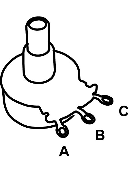
Figure 6 The three terminals of a potentiometer
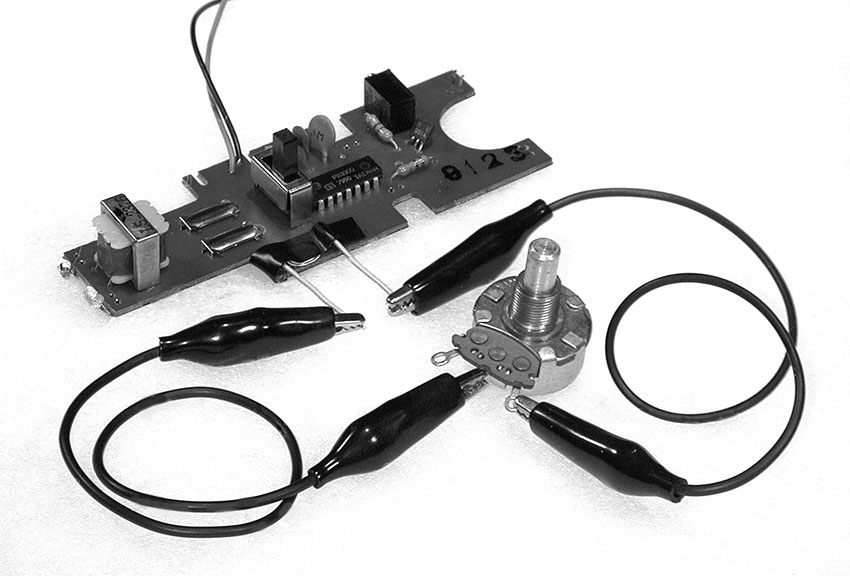
Figure 7 Pot substitute for a clock resistor.
Remove the resistor from the clip leads attached to the whiskers on your circuit board. Clip the free end of one of the leads to the center terminal (B) of your pot, and clip the other to the end terminal C (see figure 7). Rotate the pot and listen. The circuit will probably crash if you raise the pitch past a certain point and you’ll have to restart it (see Rule #12, above). But as long as you stay below that point in the pot’s rotation you should be able to coax a pretty wide range of sounds out of your circuit. If the toy appears to shut down when the clock is at its slowest, but restarts on its own when the pitch is raised again, the problem may be simply that the sound is going too low to be heard on the built-in speaker; try putting a telephone pickup on the speaker and amplify it through a bigger speaker. Of course you can always use the center terminal B and the other ear, A, but in this case the response of the pot will be backwards: the pitch will go down as you turn it further clockwise, rather than up. Which is fine, except slightly counterintuitive if you have worked with most commercial electronic music devices – there’s no time like now to start a revolution (or at least change its direction).
If there is no appreciable change in pitch or tempo you may have picked the wrong resistor as the clock timing component. Solder it back into the board and start over at step 1 probing for the hot spot with your wet finger. Other common causes of failure include torn traces (as mentioned in step 2 above), or sloppy soldering accidentally joining points on the circuit board that should remain separated.
If you removed a pitch-varying pot (instead of a fixed resistor) from the circuit you will have to experiment with connecting the terminals of your new pot to various combinations of leads from the circuit board before you find the correct hookup -- you can start by matching up the nose and ears of your replacement pot with those of the original part in the toy. Substituting a pot of larger value than the built-in one should give you a wider range of pitch/speed variation.
In case you were wondering, yes, you could also change the clock frequency by varying the capacitor in the clock circuit, rather than the resistor. But it is difficult to make a capacitor continuously variable over a wide range, and therefore this is a less practical approach to the problem of “playing” the clock. In chapter 13 we will substitute different size capacitors to set the frequency range of an oscillator, while a resistance is varied for continuous pitch change, but for now we’ll limit ourselves to experiments with resistors of various kinds.
Beyond the Pot
Photoresistors, Pressure Pads and Other Ways to Play Your Toy
You will need:
- Electronic toys and radios from the previous experiments.
- Some hookup wire.
- Test leads with alligator clips.
- An assortment of resistors and pots.
- A few different photoresistors.
- A flashlight.
- A soda straw (opaque if possible), or a short piece of heat shrink tubing.
- Some loose change.
- Anti-static foam from packaging Integrated Circuits.
- A small sheet of corroded conductive metal, such as iron, copper, or aluminum.
- A lead from a mechanical pencil.
- Some paper and a soft pencil.
- Some fruit and or/vegetables.
- A telephone pickup coil and small amplifier.
- A multimeter.
- Soldering iron, solder, and hand tools.
You’ve opened a toy, tickled the clock, replaced its timing resistor with a potentiometer, and learned a bit of theory about swapping resistors—what’s next in the way of toy hacks?
Photoresistors
A photoresistor (or photocell, as it is sometimes called) is a device that changes its value in response to light level: the resistance gets smaller when it is exposed to a bright light, and gets larger in the dark. It is small disk, whose diameter can range from 1/8” - 1”; two wires come out of one side, and the other side displays a pleasing zigzag pattern of fine lines (see figure 1). The side with lines is more sensitive to light than the other, but the back is translucent enough that light striking the back will affect the resistance as well. The lowest resistance in bright light is anywhere from 100 to 2000 Ohms, depending on the kind of photoresistor; the “dark resistance” is very large, typically around 10 megOhms. Because this is higher than most pots, and because most clock circuits use pretty large resistors, photoresistors are a convenient variable resistor for slowing down toys a lot.
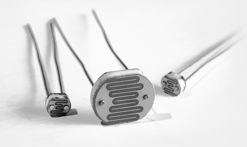
Figure 1 Some photoresistors
Photoresistors are pretty cheap. Some retail sources provide data on the range of resistance, sometimes not. In addition to different “light” (minimum) and “dark” (maximum) resistances, different photoresistors will respond at different speeds to changes in light level—some are more sluggish than others. All these factors affect how they perform in a musical circuit. You can test them with a multimeter, but ultimately your ear is the best guide to picking a good photoresistor for your circuit. Don’t be disappointed if it takes a while to find the perfect one.
Select a photoresistor. Remove the pot from the clock circuit of a toy. Using clip leads, attach the two leads of the photoresistor where the pot tabs were connected, or solder it directly in to the holes left when you removed the resistor (see figure 2). Turn on the toy and listen to how the circuit behaves when you pass your hand over the photoresistor or shine a flashlight on it. If you have more than one type of photoresistor swap them in and out, and listen to how different ones affect the circuit.
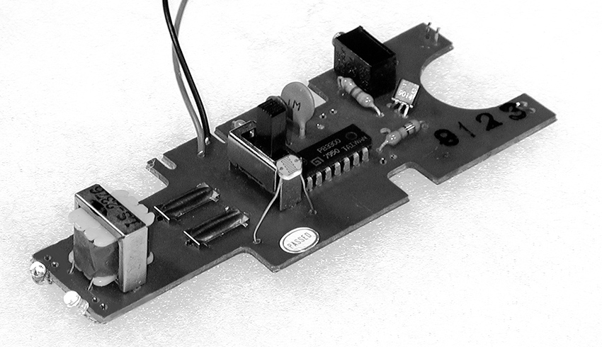
Figure 2 Photoresistor in place of a clock resistor
For maximum resistive range you must go from totally black (no light at all) to high illumination – carry your circuit into a closet and play it with a flashlight. More practically, you can mount the photoresistor at one end of an opaque tube (such as a drinking straw painted black, or a short piece of heat shrink tubing) to make it very directional in its light sensitivity: it will only respond to light aimed directly down the tube (see figure 3). This is the core technology of certain carnival shooting galleries, where each “gun” fires a light towards similarly blinkered targets.
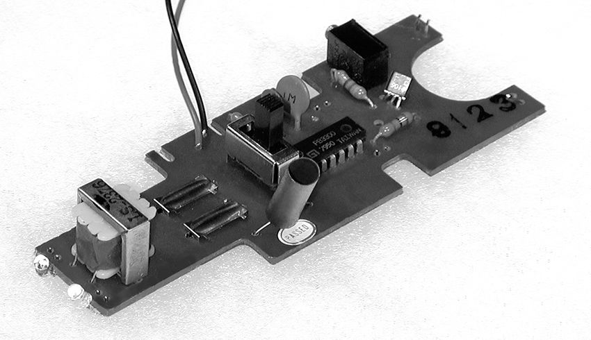
Figure 3 A shy photoresistor hiding inside a section of heat-shrink tubing.
You can put the photoresistor in your mouth and make a very expressive controller that responds to changes in both the light level as you open and close your mouth, and in the conductivity of your saliva-laden tongue across the photoresistor’s bare legs (a suggestively naughty extension of the licked-finger-on-circuit-board effect).
DON’T EVER THINK OF TRYING THIS WITH ANY CIRCUIT THAT IS EVEN BATTING ITS EYELASHES AT A WALL OUTLET!
Place a fan between a light source (such as flashlight) and the photoresistor, or reflect light off a record turntable (put some delicately crumpled aluminum foil on the turntable instead of a record)—you should hear a vibrato effect or other wobbly modulation, which changes as you vary the speed of the fan or turntable.
If the toy has blinking lights or LEDs you can tape the photoresistor against one of the lights and the toy will modulate itself, producing possibly interesting patterns. Two toys with blinking lights and photoresistor-controlled clocks can modulate each other—curiously erotic electronics! The more toys, the greater your chances of creating artificial life.
A photoresistor can be a good compromise between the fluid, if somewhat unpredictable (and occasionally dangerous), effect of the finger on the circuit board and the more controllable but less expressive potentiometer. You can use it as a very responsive performance interface to interpret hand shadows or flashlight movement, or as an installation sensor, reacting to ambient light and the shadows cast by visitors. We’ll look at more photoresistor applications in chapters 13 and beyond.
As I mentioned earlier, although the zigzagged side is more sensitive to light than the backing, most photo-resistors are made of translucent material, so that light striking the back will affect its resistance as well. It is important to cover the back if you want the greatest range. Besides burying the photoresistor in an opaque straw, you can seal off the back with black paint or electrical tape.
If you want to both the gestural quality of the photoresistor and the controllability of the pot, you can combine the two: if you wire a pot in series with a photoresistors (see figure 4), the pot will determine the maximum frequency of the clock in full light, and darkness will cause the speed to go down from that maximum. If you wire the pot in parallel with the photoresistor (see figure 5), the pot will set the minimum frequency of the clock in full darkness, from which the speed will go up as light increases. (If this sounds confusing, just try it).
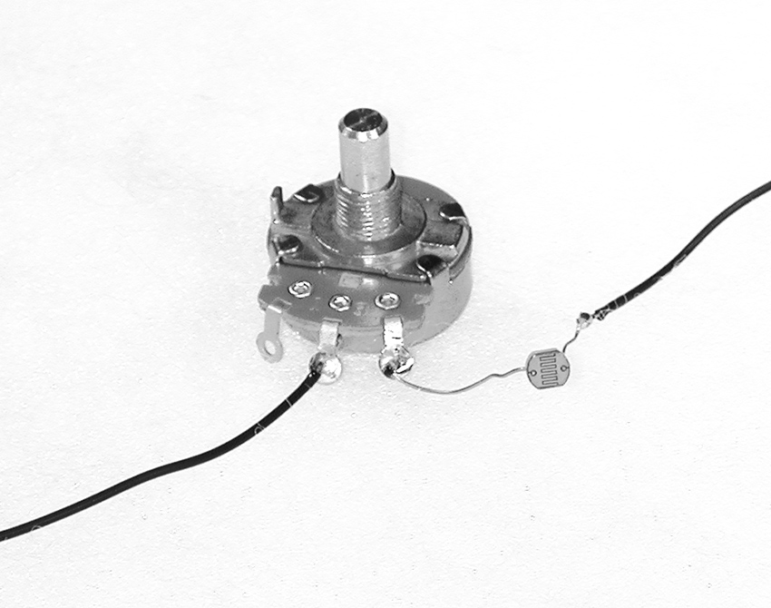
Figure 4 A potentiometer and photoresistor in series.
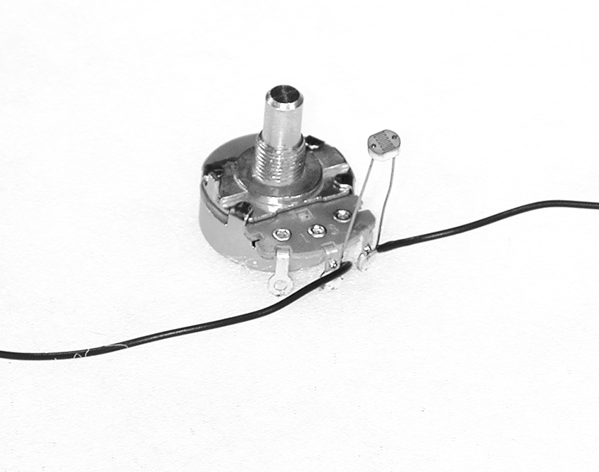
Figure 5 A potentiometer and photoresistor in parallel.
In total darkness, the photoresistor has a very large resistance—as high as 20mOhm— much higher than any commonly available pot. If you want really low frequencies out of your toy a photoresistor is the way to go – moreover, multiple Photoresistors can be strung together in series to drive a clock down into the glacially slow range.
Electrodes
Let’s not forget the heady spontaneity of our youthful experiments with flesh-controlled circuitry back in chapter 12. If you want to use your fingers to connect points on the board that are widely separated, or you just want a more formal playing surface, dimes or other silver-plated coins make excellent electrodes (copper tarnishes too quickly in an urban or coastal environment—just take a look at the Statue of Liberty). Strip 1/4 inch of insulation off both ends of a few 5 inches pieces of wire. Solder one end of each wire to one of the “sensitive points” you’ve found on the circuit board, and solder the other end to a coin. Arrange the coins in a pattern that lets you bridge them easily with your fingers, but avoid direct shorts (see figure 6). By the way, I was told as a child that it is illegal to solder or similarly deface U.S. currency, so you might refrain from performing on this one in the presence of the Secretary of the Treasury.

Figure 6a Coin electrodes and their use in performance.
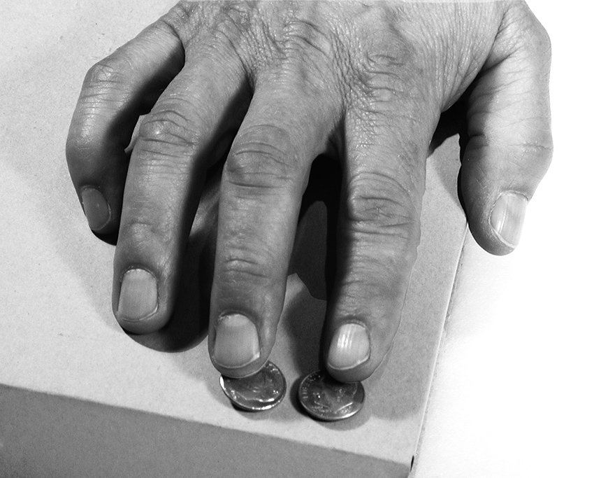
Figure 6b Coin electrodes and their use in performance.
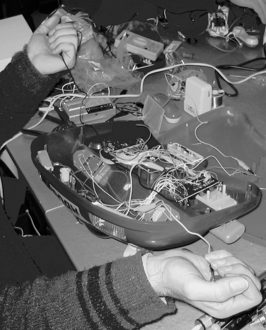
Figure 6c Coin electrodes and their use in performance.
A nice way to combine the control certainty of a potentiometer with the gestural possibilities of finger-on-circuitry is to parallel the pot and a pair of electrodes, as we did with the photoresistor in figure 5. When you solder your hook-up wires to the lugs of the pot leave an extra inch of bare wire sticking up through the solder hole. When you go to mount the pot in the box that will hold the circuit , drill small holes to line up with the wire ends and two more about 1/2 inch away. Lead the bare wires up through the panel at the pot and then down again, so that they form two parallel strips (see figure 7). You will have convenient electrode contacts immediately adjacent to the knob so you can slip your finger back and forth between precision adjustment and touchy-feely playing (you could also solder coins to these wires for a larger playing surface).
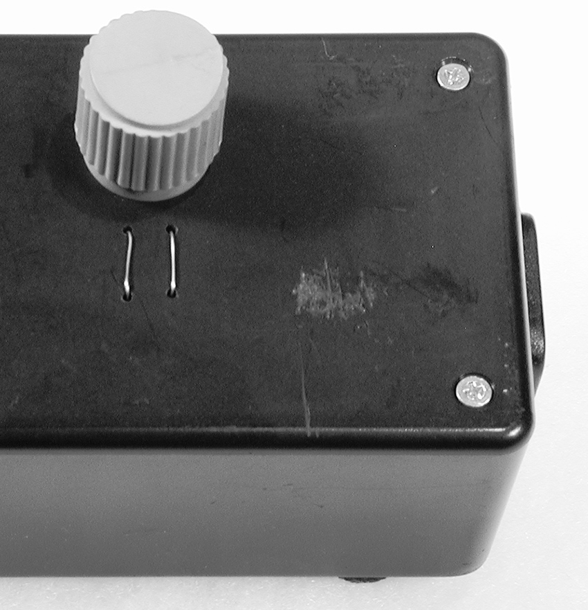
Figure 7 A potentiometer with electrodes in parallel.
Cheap Pressure Sensors
The squashy black “antistatic foam” in which Integrated Circuits are sometimes packaged has interesting electrical properties. Put a piece between two coin-electrodes and measure the resistance with a multimeter as you squeeze them together—it gets lower as you apply more pressure (see figure 8). This homemade pressure sensor can be used in place of a pot or photoresistor to make a pressure-sensitive controller for performance or installation (under chair legs to measure weight, for example). Antistatic foam can be bought in sheets from various online retailers, if you can’t find an engineer’s garbage pail from which to scrounge.
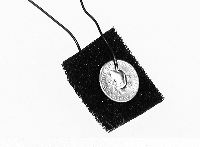
Figure 8 Pressure sensor made from anti-static foam and two coins.
Vegetables and fruit also have resistive value. This value changes as they dry out or are squished. You can substitute small slices of produce for the antistatic foam in the above experiment, or poke bare wires directly into carrots or apples. (As some of you may remember from childhood science experiments, it is also possible to make a battery out of fruit or vegetable – see “Power Supplies” inn the Technical Bootcamp section of this website).
Arty
A pencil lead from a mechanical pencil makes an excellent, if delicate, resistor (see figure 9). Attach two clip leads to the clock resistor contact points in your toy. Clip one wire to one end of the pencil lead, and scrape the jaws of the other along the lead. Resistance is proportional to the distance separating the contact points, so the pitch of the toy should go down as you move the clip further from the end. (Most potentiometers are simply a neatly packaged strip of carbon with a moving wiper.)
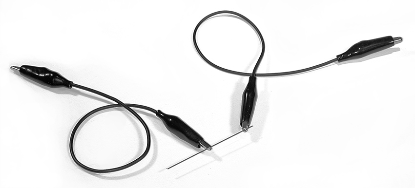
Figure 9 A pencil-lead resistor.
The use of graphite as a resistor is not limited to pencil leads themselves. Draw two blots near the edge of a piece of paper, and clamp the jaw of a clip lead to the paper at each blot; clip the other ends of the leads to the clock resistor contact points in your toy (see figure 10). Draw a line between the two blots and get the toy running—as you widen the pencil line linking the blots, or draw additional lines, the pitch should go up. Why? The wider the graphite path between the clips the lower the resistance (think fat pipes versus skinny pipes.) Patrick McCarthy has made functional rotary potentiometers using this technique (see his video in the “Circuits” section of the Gallery on this website).
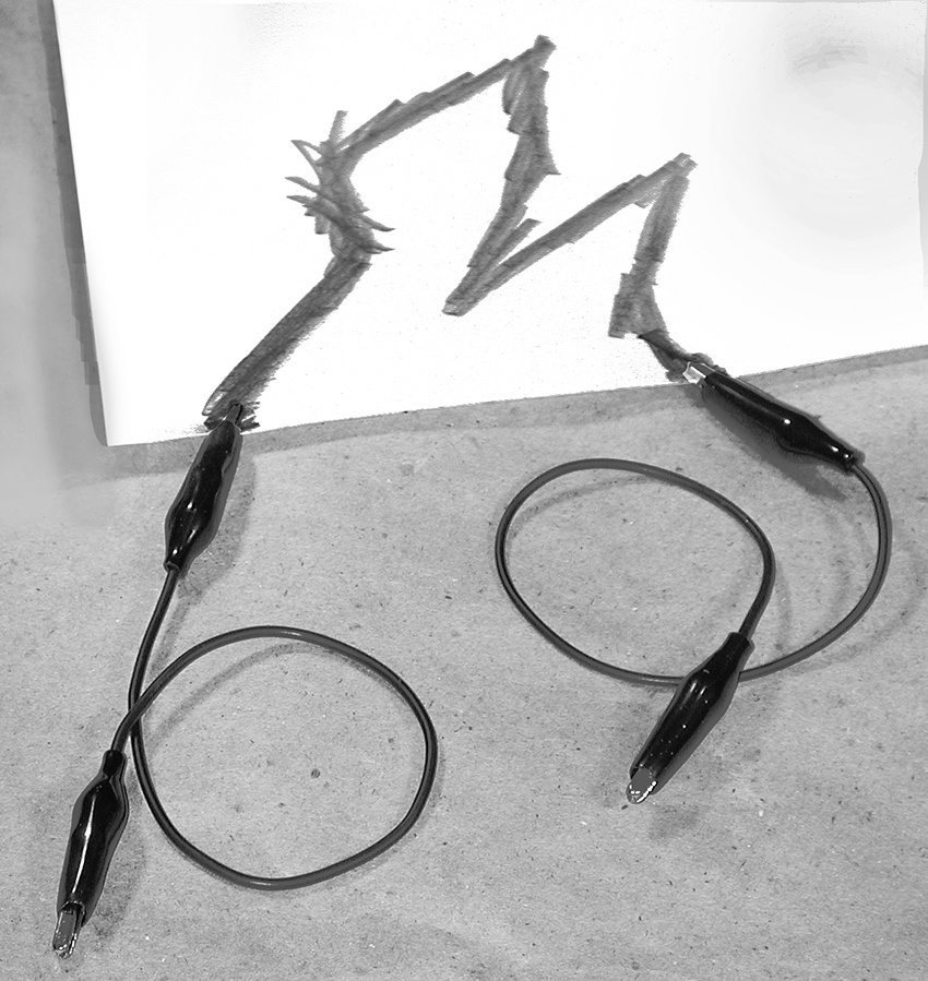
Figure 10 Drawing a resistor.
You can also use a strip of magnetic tape as an open-air resistor (old VHS tape works great): use two probes pressed against the surface, or an alligator clip at one end and one movable probe. As with the pencil line, resistance is proportional to distance. T. Escobedo’s “Synthstick” is a glissando-based instrument, sort of a cross between a Theremin and a Stylophone, based on this principle.
Almost a Short Circuit
Enough of clocks! Sometimes a toy can be induced to make curious sounds if you make new connections between various locations on the circuit board. Take a resistor in the range of 10-100 Ohms and bend it into the shape of a croquet wicket. While listening to the toy, press one end of the resistor to a solder point on the solder side of the board; then touch the other end to various other points—if the circuit board is large you may need to use a clip lead to reach all over (see figure 11). You may (or may not) get some interesting sounding circuit malfunctions. Disconnect immediately any connection that seems to cause heat, smoke, or flame.
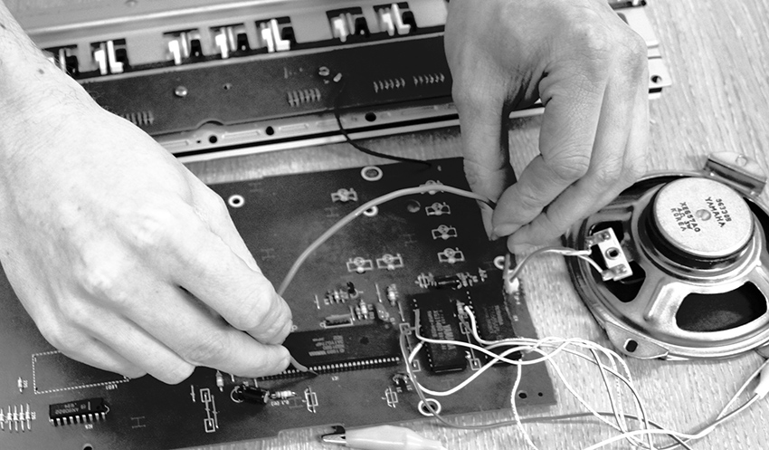
Figure 11 Phil Archer bridging the circuit board. Photo © Phil Archer, used by permission.
Try different value resistors but avoid shorting out the board with straight wire unless it’s the only thing that works (see the 7th Rule of Hacking). If you find that the best sounds happen with the smallest value resistor, you can try a straight wire, but do so gingerly and be prepared to remove the wire as soon as you feel or smell trouble. You can also try using pots or capacitors instead of resistors. You can go back to your radio and experiment with using resistors to jump between the hot spots you bridged with your damp finger.
Once you find a useful connection you can solder the resistor permanently into place, or add a switch to connect and disconnect it as a performable change (see next chapter for switch information).
This technique is the heart of Reed Ghazala’s wonderful Circuit Bending philosophy of hardware hacking, and is a very powerful and creative tool for extracting unusual sounds from almost any found circuit (see “Circuit Bending” essay on this website).
If you’re feeling suicidal, you can follow Phil Archer’s lead and dribble water on the circuit board – watch his video in the Circuit Bending section of the Gallery on this website, and watch out!
Rusty
A corroded metal plate and a nail can serve as a quasi-random variable resistor, as we demonstrated with the jumping speaker in chapter 3. Choose any two points on the circuit board that produce a change when they are connected to one another—this could be the clock resistor solder pads, or any of the hot spots we’ve just described bridging with resistors. Solder a short wire to each point, long enough to be grasped in the jaws of a clip lead. Clip the other end of one of the leads to a nail and the other lead to a sheet of rough or corroded metal (copper flashing, rusty baking sheet, file, etc.). Lightly scrape the nail across the metal and listen to the circuit twitter—the corrosion and intermittent hop, skip, and jump of the nail over the rough micro topography yields an ever-fluctuating resistance that can be steered (if not exactly controlled) by adjusting the pressure and speed of movement.
Motor-Mouth
Noise, flashing lights, and frenetic activity—the essential attributes of any disaster are also the core components of a successful toy. After messing around with the sounds and lights, don’t forget the motors that make tickled Elmo twitch and Billy Bass flap his tail. Some pretty sophisticate computer code goes into this electromagnetic choreography, and you can eavesdrop on it by placing a telephone tap coil on a motor and connecting the coil to your amplifier. There is often a beautiful rhythmic interplay between the toy’s sounds, blinking lights and movements, and a thorough hack can bring all this futurist polyphony to the ear. And don’t forget to try another coil on the toy’s speaker to make the basic sounds louder and wider range (as we did with the radio in chapter 12).
Interconnecting Toys
Once you’ve opened and hacked a few toys don’t be afraid to experiment with interconnecting them. First connect a clip lead between the grounds (“–” end of the batteries) of both toys. Then use another clip lead to make random connections between any point on one toy and any on the other. Use a jumper between the clocks and you may get the toys to cross modulate each other; if you connect clock points between two circuits and remove the resistor from one, you can sometimes drive both in sync from a single clock.
Remember that you can also link circuits through blinking lights and photoresistors, as described earlier in this chapter.
Lest you get too distracted by the gizmo-factor of all these add-ons, don’t forget the humble laying of hands. On larger circuit boards with multiple components (such as musical keyboards) a few damp fingers brushed against the circuit board can raise delightful havoc with the normal behavior of the toy—the Yamaha PS-140 is especially susceptible to fleshly corruption (see figure 12). British bending iconoclast Dan Wilson lets worms crawl across his circuit boards (see his video in the “Laying of Hands” section of the Gallery on this website).
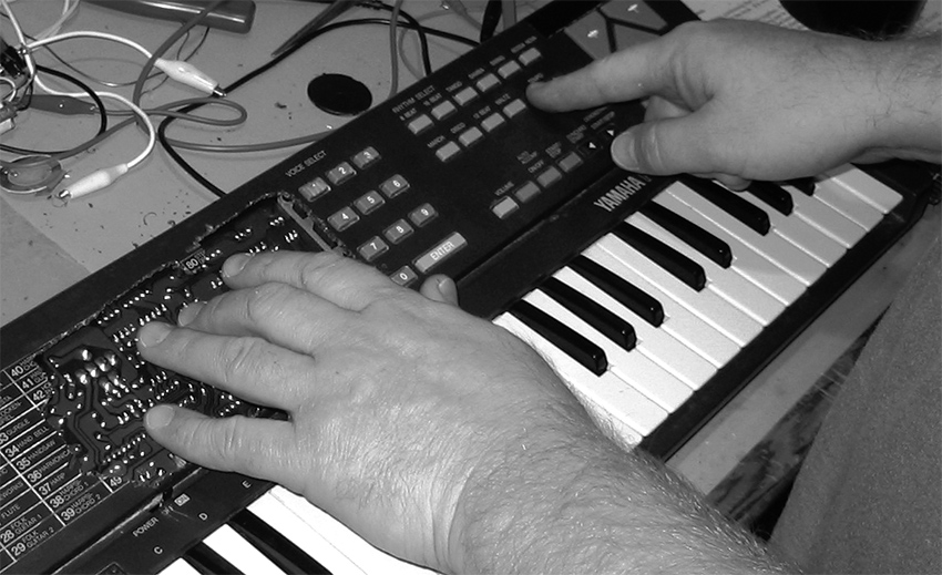
Figure 12 Mike Challis playing his hacked Yamaha PS-140 by touching the circuit board through a hole cut through the case.
Beyond Toys
Most of the techniques described in this chapter can be used to extend the radio you opened up in chapter 12 as well: electrodes can be used to pull the radio’s ticklish spots to the outside of a box, and make it easier to bridge multiple points with your fingers; pots, photoresistors, pressure pads, resistors, and rusty nails can be used to link these points as well. Toys and radios are cheap and plentiful, and thus an obvious flashpoint for hacking insurgency, but the same methods can be applied to almost any electronic circuit: CD players (see figure 13), rock effect pedals (“stomp boxes”) (see figure 14), cassette players, answering machines—you’ll never know until you try them. Vic Rawlings (US) uses wire brushes, nails, fingers and assorted metal junk to play a complicated array of effect pedals – see his video in the “Laying of Hands” section of the Gallery on this website and figure 15. Neal Spowage (UK) has hacked metal detectors to make his “Electro Magnetic Wands” (see his video in the “Coil Pickups” section of the Gallery on this website).
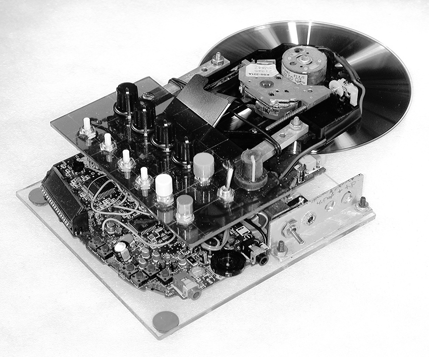
Figure 13 “Sled Dog” hand-scratchable hacked CD player (Nicolas Collins).

Figure 14 Hacked guitar effect pedal with electrode contacts for toes, Chris Powers.
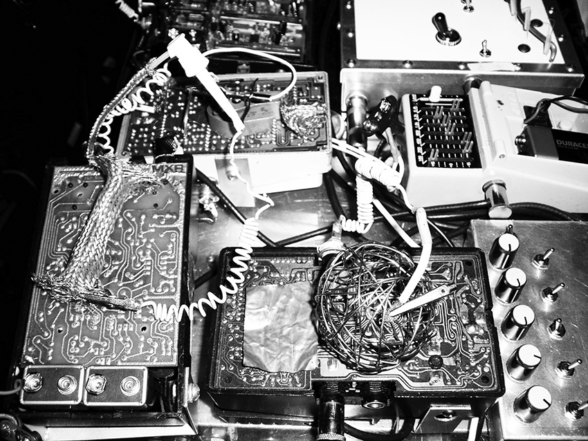
Figure 15 Performance setup showing open effect pedals with wire ball, Vic Rawlings. Photo © Vic Rawlings, used by permission
You can buy dozens of different kinds of electronic kits, from strobe lights to wind chimes, from online retailers and experiment with these kinds of modifications as you build them—hacking goes faster if you don’t have to disassemble first. After savoring bespoke electronics you’ll never accept off-the-rack again.
Video Music/Music Video
Translating Video Signals into Sound, Hacking Cameras, and Extracting Sounds from Remote Controls
You will need:
- A video camera or camcorder (it will not be destroyed).
- A video monitor.
- A cheap, hackable CCD video camera circuit board.
- Some phototransistors.
- Some photoresistors.
- A 74C14 Hex Schmitt Trigger.
- A CD3093 Quad NAND Gate.
- An infrared remote control from a TV or other appliance.
- An audio amplifier.
- Some raw speakers of various sizes.
- Some small mirrors, a laser pointer or flashlight.
- A piezo disk.
- Optional: surplus barcode reader
Various ingenious software tools exist for translating pictorial data into sound and vice versa: Soundhack’s “Open Any…” turns any computer file into a sound file (i.e., a Photoshop-to-hit-record converter), STEIM’s “Big Eye,” and Max’s “Jitter” track moving objects in a video image and extract MIDI or audio information. Chapter 22 details a number of circuits for video hacking. But here are a few super-simple hacks to get you started.
Light and Shadow
Several artists have translated images directly to sound by placing photoresistors on video monitors or projection screens (see “Visual Music” on this website). Wire up a few photoresistor-controlled oscillators (see chapter 13), using long sections of stranded wire to connect the photoresistors to the circuit board. Place the sensitive side of a photoresistor against the screen of a video monitor and use a thin strip of opaque electrical tape across the back to hold it in place; repeat for each photoresistor, distributing them across the screen. Connect a camera or other video source to the monitor and listen as you sweep the camera across the room or play back a tape. Action! Instant soundtrack! You can do this on a projection screen as well: -- the effect is stronger with film projection than video because of the increased contrast between light and dark. LCD screens on laptops work but have considerably less contrast. In brightness, so the pitch changes will be less dramatic.
You can also use the photoresistors to adjust the loudness of any audio signal (CD, computer, microphone, etc.) in response to fluctuations in the image, by adapting the gating and panning circuits from chapter 17 to work with photoresistors affixed to a monitor or projection screen. You can adapt the Theremin circuit in chapter 15 (figure 15.9) for video response as well – using the image to control both pitch and volume of multiple oscillators gives the resultant texture considerably more variety.
Frame Rate Music
We can also listen directly to a video signal itself. Use a Y-cord to split the analog video output of a camera. Connect one leg of the Y to a video monitor and the other to an amplifier and speaker—that’s right: the video output to the audio input. As luck would have it, a camera puts out a video signal that is approximately the same amplitude as a line-level signal from a CD, etc. Pan the camera around the room as you listen. You should hear a steady drone whose overtones fluctuate in response to the image content and brightness. The fundamental pitch is a function of the video frame rate (between B flat and B natural with NTSC video, between G and G# with PAL, and therefore unwavering if the camera is functioning normally, while the overtone balance directly represents the image data, line by line. Very nice, if you like drones.
Aim the camera through a rotating fan; vary the fan speed and you should hear interference patterns between the frame rate and the fan speed. Focus on a white card off-center on a black turntable mat, and switch the speed between 33 1/3 and 45rpm. Aim the camera at the monitor and look and listen as you experiment with video feedback. A video mixer, keyer, or special effects box introduces audible artifacts as well as visible ones. With a Y-chord splitter you can see and hear the effects – this is a technique used by several experimental VJs and video artists, including Jon Satrom, Billy Roisz and LoVid (see “Visual Music”). Aim an IR remote at the camera (most video cameras detect infrared light and display it as hot white) and listen to the burst pattern of the encoded data (see Channel Surfing Music below).
You can similarly listen to the video output of your DVD player - fanning it will have no effect, but it’s an easy way to generate an automatic soundtrack.
The frame rate is fixed, and normally doesn’t budge unless you move between NTSC and PAL. But if you invest in a cheap black and white CCD camera circuit board (scrounged from a surveillance camera, or available from most electronic surplus outlets for a modest price), you can experiment with tickling the clock frequency by a laying of hands (as we did in chapters 12) or replace the clock crystal with a variable oscillator (as discussed in chapter 15). The crystal is usually pretty conspicuous on the circuit board—often a metallic silver small cylinder or block (see figure 1).
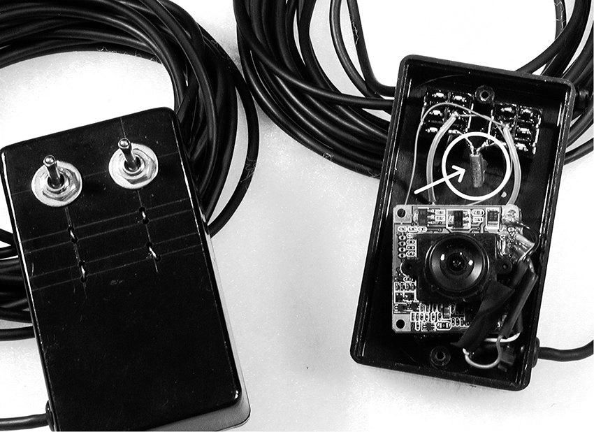
Figure 1 Crystal removed from hacked surveillance camera.
Split the camera output between a video monitor and amplifier using a Y-cord as before, so you can see as well as hear the effect of your hack. The video image produced by a tickled camera is reminiscent of 1960s 8mm film scratch-animation, and the sound is somewhat meatier than the typical hands-upon-radio swoops. Sometimes lifting one leg of the camera’s crystal time base makes it just unstable enough to produce a coherent image when left alone, but jitter like crazy when touched (I have no idea how this can possibly work, but it does). If you replace the crystal with your own adjustable clock circuit you can to transform the video camera into an oscillator whose pitch is controlled by a pot, photoresistor, sequencer-driven 4046 VCO, etc., but whose timbre is a function of what it sees. To the best of my knowledge no-one has built a synthesizer with such a hacked camera as its basic oscillator module, so jump on this one.
The hacked camera will not generate a stable sync signal when tickled. Old fashioned CRT video monitors will continue to display scratchy video in the absence of a stable sync, but video projectors and LCD displays are too “smart”: they will interpret intermittent or erratic sync as an indication that there is no video signal at all, and will display that irritating blue screen with the wrist-slapping observation “no video input.” Circuits to provide a proper sync under scratch video is discussed in chapter 22, but if you want to get started quickly, send the hacked camera signal to an old TV or CRT monitor; then focus a functioning video camera at the screen and send this signal to the projector. Or invest in a cheap video mixer, keyer or other device that generates its own sync or lets you patch in a second, “normal” camera for sync (see chapter 22).
As long as we are on the subject of old TVs, I would be remiss if I did not remind you, the reader, of the beautifully liquid image distortion that results from putting a hefty magnet in close proximity to a television picture tube (ineffective on modern LCD screens). Take an old TV. Tune it to any station or even inter-station static. Move a big magnet over the top and sides, and watch the image wiggle—a gift from Nam June Paik (see “Visual Music” on this website).
I must warn you once again of the electrocution hazards posed by all of the above projects. The fingers-on-circuit activities have the usual risk:
EXERCISE EXTREME CAUTION WHEN CONNECTING THE CARESSED CAMERA BOARD TO ANY AC-POWERED VIDEO MONITORS OR PROJECTORS.
But the greatest danger is with the magnet-on-TV experiment is that the circuitry inside old-fashioned TVs and video monitors (the kind that use “picture tubes” instead of LCD screens) actually steps up the wall voltage from a deadly-enough 120/240 volts to several thousand volts (kilovolts, as they are known – although we might dub them “killervolts”). Please, no matter how much you want to get the magnet closer to the tube:
Do not open UP the TV or you’re in for a nasty shock. (Or invest in a pair of elbow-length insulated rubber gloves – “lineman’s gloves” – before you get to work with the screwdriver.
Video-Free Video
Visual display of sound patterns can be accomplished without video cameras and monitors, of course. As we mentioned at the end of chapter 3, you can take a large raw loudspeaker, fill it with sand or talcum powder, connect to an amplifier, play some sound, and watch the dancing dust. Coat the inside of the cone with paint or rubber cement, fill it with water or oil, and repeat the experiment; you can reflect a focused light or laser pointer off the water’s surface onto the wall or ceiling (see figure 2). A mirror glued to the center of the cone also reflects a laser nicely. Planetarium laser shows use electromagnetic transducers called “galvanometers” to deflect mirrors on several axes – sometimes these gizmos turn up on surplus sites, but the old speaker-and-mirror technique works pretty well.
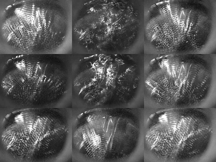
Figure 2 Water-filled speaker, showing ripples produced by low-frequency sound.
Channel Surfing Music
In chapter 6 we used coils to pick up the electromagnetic signals given off by various appliances and electronic devices. We can also eavesdrop on light signals of various kinds by using a specialized type of photosensor: the phototransistor (a variant on the photoresistor we’ve used throughout the book). A phototransistor is the heart of any infrared remote control receiver circuit, such as that in your TV. Most look just like an LED, so make sure you keep them clearly separated in your parts collection. You can find them at any electronic parts retailer. A phototransistor detects the pulses of infrared light sent by your remote control and converts them into a stream of binary pulse waves that are, in turn, translated back into digital data by the microprocessor in the TV. Earlier in this chapter we detected these data burst using a video camera, but phototransistors are cheaper (and smaller).
Aim a remote control at the simple circuit in figure 3. Keep it close, and you should hear pulse trains as you press the buttons. If not, reverse which leg of the phototransistor connects to +9 volts and which connects to the load resistor. Normally the phototransistor is “off” and the 2.2kOhm resistor holds the output to ground (0 volts). When infrared light strikes the phototransistor it turns on and effectively connects the output to +9 volts. Bursts of light from the remote causes the output to switch between 0 and 9 volts, just like our old friend the CMOS oscillator, only here the waveform is not a simple square but instead a cycling sequence of pulse waves of various duty cycles, which has rather a different timbre.
The variation between one button and another may sound pretty subtle: although the encoded numbers is different, the base frequency remains the same -- the effect is similar to listening to video, where the constancy of the fundamental sometimes overpowers the variations in image-dependent overtone content. Try several different remotes. You’ll notice that the loudness of the signal falls off pretty sharply as you pull the remote farther from the circuit, so you do have some dynamic control over this instrument.
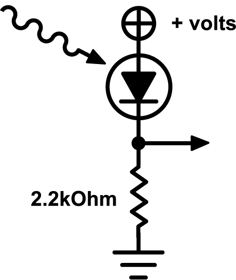
Figure 3 Simple phototransistor-based infrared detector circuit.
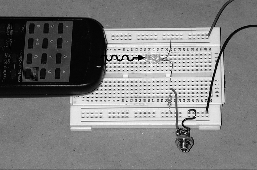
You can substitute an ordinary photoresistor for the phototransistor. You may need to increase the size of the load resistor from 2.2kOhm to 10kOhm or larger, as shown in figure 4. Because photoresistors are sensitive to light across the spectrum (not just infrared), you will get much more interference from the power grid’s AC frequency present in incandescent and fluorescent lighting (60hz in the United States, 50hz in Europe), resulting in an underlying drone. But you may find this interesting rather than irritating, so try it.
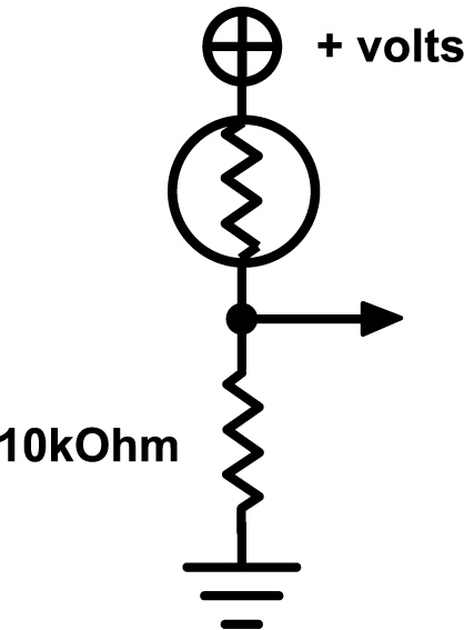
Figure 4 Photoresistor-based infrared detector circuit.
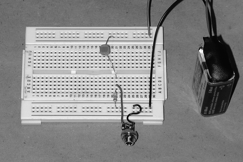
Although the lights on many electronic devices look steady, most are in fact “scanned” by the central processor unit. You can use our light-detector circuits to extract unexpected sound patterns from almost any gizmo with LEDs. Try it on bicycle flashers, toys with blinking lights, the front panels of studio gear, TV screens, computer monitors (as demonstrated in several audio and video tracks in the “Visual Hacking” gallery on this website). Certain bicycle lights and blinking toys sound astonishingly much like heavy metal chord progressions.
For greater variation try using the phototransistor or photoresistor circuit above as the control input to the basic 4093 gateable oscillator circuit from chapter 15. If you also use a photoresistor for the oscillator’s frequency control resistor, you get a pretty expressive “multi-phase” light-to-sound converter that responds to both ambient and modulated light sources, such as remote controls (see figures 5 and 6). Add a Theremin-style control of output volume (see figure 15.9) for additional expression.
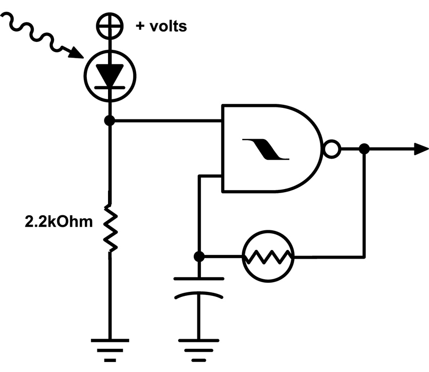
Figure 5 Infrared-gated oscillator with photoresistor-controlled frequency.
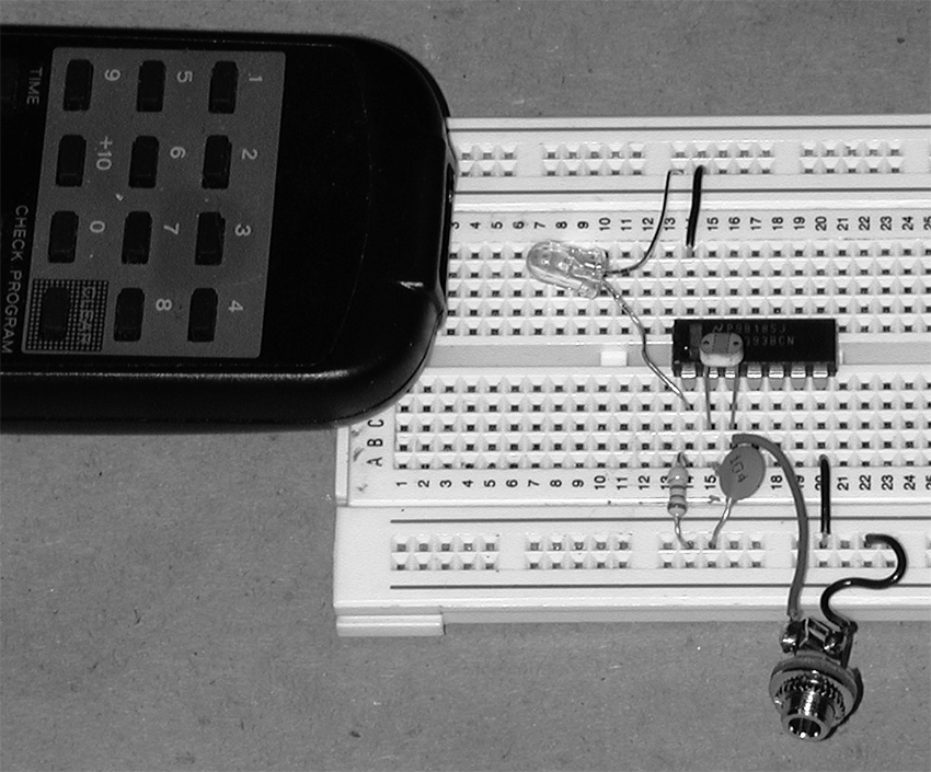
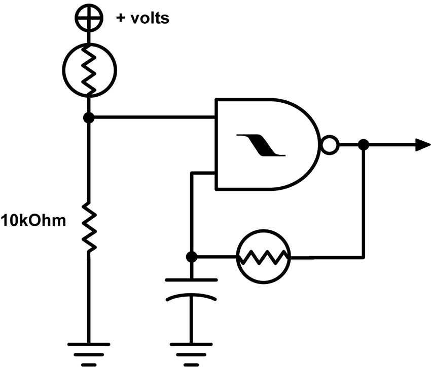
Figure 6 Photoresistor-gated oscillator with photoresistor-controlled frequency.
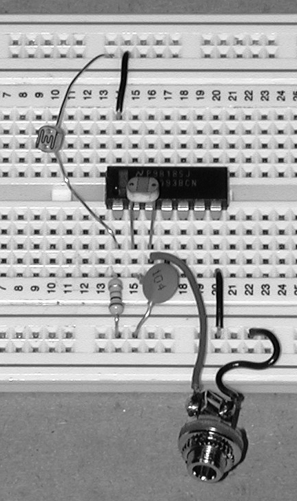
For a battery-free alternative you can connect a dozen or so phototransistor in series and hook either end of the chain up to the leads on a piezo disk (see figure 7). Aim an infrared remote at your circuit and you should hear a quiet, tinny refrain of the familiar pulse train. As we suggested at the end of chapter 15, clamping the disc to a resonator of some sort (matchbox, pie tin, etc.) will increase its loudness. Engineers at the Information Technology Research Institute at the National Institute of Advanced Industrial Science and Technology (Japan) used a similar passive design for an installation by Laurie Anderson in a Japanese Garden in Expo 2005 in Aichi, Japan. Visitors participating in “Walk” could listen to poems in four languages, transmitted with infrared light, and picked up by handheld “Aimulets” (see figure 8).
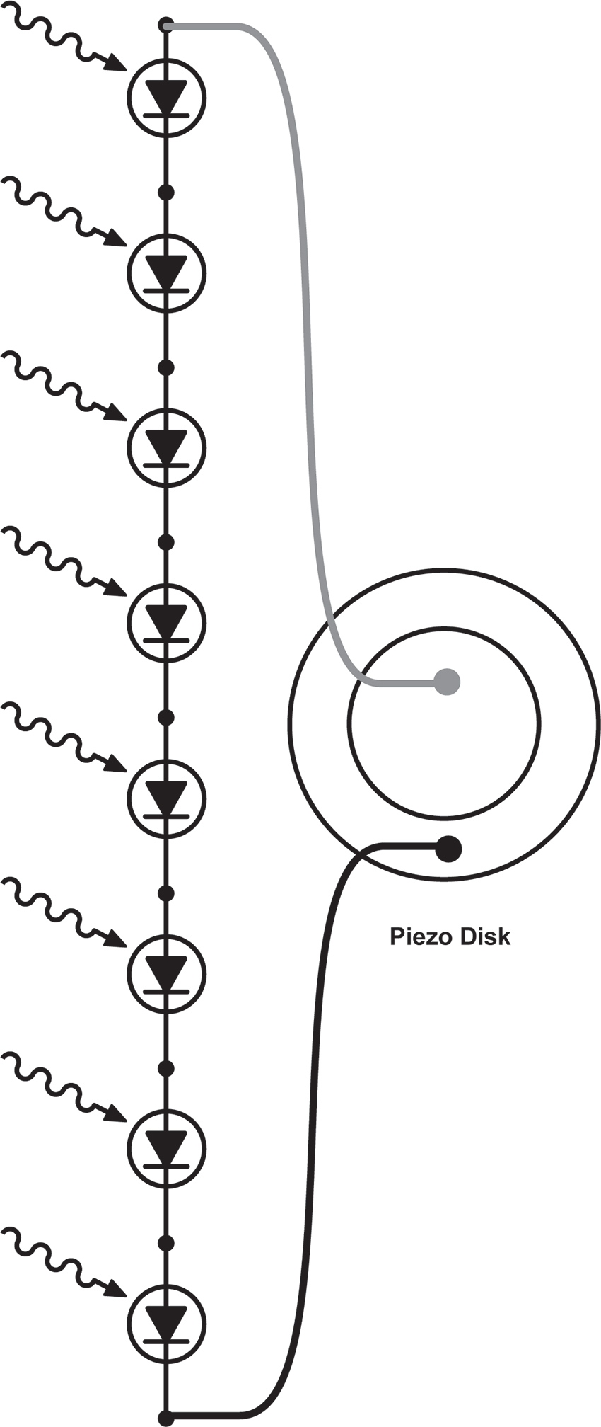
Figure 7 Phototransistor ladder driving a piezo disk.
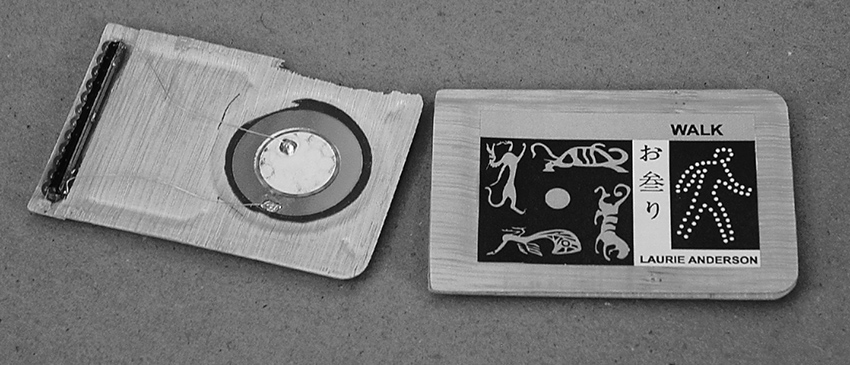
Figure 8 Walk by Laurie Anderson: photodiodes driving piezo disk directly, with molded bamboo resonator. Designed by the Information Technology Research Institute at the National Institute of Advanced Industrial Science and Technology, Japan. Photo © Laurie Anderson, used by permission of Laurie Anderson/Canal Street Communications.
Infrared transmitters and detectors are combined in the barcode readers used in our UPC dominated world – from handheld wands to the deliriously diffracted laser beams at supermarket checkout, all work by bouncing light off packaging and detecting the difference between light and dark stripes. Handheld devices, and their core elements, can be found quite easily and cheaply from electronic surplus sites on-line. Most require a 5-volt power supply (try 3 AA batteries in series). Sometime they come with wiring data, otherwise you’ll have to decode it (buy a few, in case of a real flameout). Hook up power, connect the data output to an amp, pass the wand across some barcode, and you’ll be rewarded with a noisy waveform similar to the tape head scratching transit cards in chapter 10 (no surprise here, since both the magnetic tape and the UPC are encoding binary data).
Since the barcode reading mechanism detects any light/dark difference, they can be used as generic image-to-sound translators: pass them over newsprint, photographs, TV screens, Dalmations, tattoos, facial stubble… Figure 9 shows two wands with a homemade power supply. The batteries are all that’s really needed, the extra circuitry in this box causes each wand’s data stream to alternate between the left and right output channels with each pulse, for a little more variety.
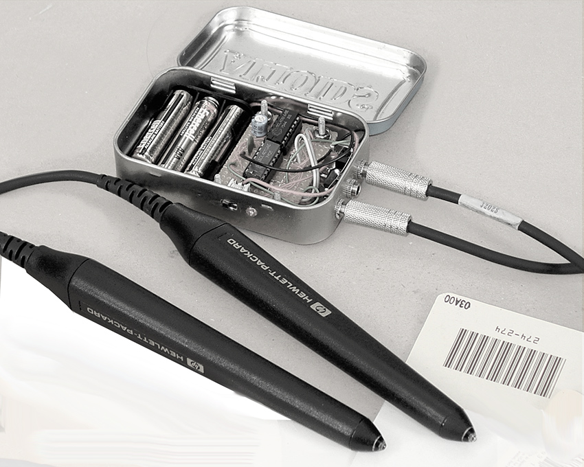
Figure 9 Two wands with a homemade power supply.
LCD Art
Making Animated Modern Daguerreotypes and Alternate Video Projectors
You will need:
- A toy with an LCD screen.
- Some test leads.
- A 9-volt battery and battery hook-up clip.
- Hookup wire.
- Some straight pins or short needles.
- A basic oscillator circuit from chapter 13 or 15.
- An amplifier.
- A flashlight and some lenses
- Hand tools, soldering iron, and electrical tape.
- Optional: an old-fashioned slide projector.
- Optional: a “video paint-box” toy with video output.
Lower Tech
A lot of handheld toys and games incorporate small LCD screens. In general-purpose LCD displays - such as laptop screens, flat-screen TVs, Gameboys and cellphones -- a matrix of pixels is bit-mapped in rows and columns by a microprocessor that turns individual pixels on and off to “draw” any character or image, etch-a-sketch style. In cheap toys, on the other hand, the screen usually contains a handful of “ready-made” graphic components: lips, a nose, and pair of ears are turned on and off against a printed cardboard backdrop to add distinguishing features to Mr. Potato’s otherwise generic oval head, for example. Although this approach severely limits the graphic options of any individual toy, it is much simpler from a programming standpoint, and therefore cheaper to manufacture.
These rebus-like images take on new meaning when the background is removed—leaving the body parts floating like a medium’s apparitions—or superimposed on an alternative drawing or photograph that you provide (Mr. Turniphead? Baby Sister rev. 2.0?). To accomplish this gentle re-purposing, disassemble the toy carefully (don’t lose those tiny screws or tear any fine wires), remove the cardboard backdrop, insert a new one of your choice, re-assemble, and prepare to amuse your friends.
The “narrative” of the game can sometimes be disrupted by shorting various points on the board, as we did in the “Almost a Short Circuit” section of “Beyond The Pot” on this website. In some cases injecting an amplified and distorted audio signal can also confuse or modulate the imagery (see chapter 20 for suggestions).
Although fewer in number than the tiny pixels in bit-mapped pixel grid, these graphic elements are still arranged in a matrix: the toy’s computer turns on individual images by sending logic signals through a particular row and column pair. When the screen is removed from the circuit its graphic elements can be activated with simple connections of voltages, either directly from a battery or from an oscillator. Start by tinning the tips of the red and black wires from a 9-volt battery clip to give them stiff, sharp points—you can also solder sewing pins to the wires for stronger, finer contacts.
Locate the connections to the LCD. The glass element is often connected to the circuit board through a thin rubber strip (usually pink, for some incomprehensible reason) containing a thinner strip of black conductive rubber filaments. If you look closely you’ll notice that what at first may have appeared as a solid stripe actually resembles a dotted line – each dot is one end of a thread of the same material as those funny rubber hats used as keys on many toys. One end of each of these filaments presses down against a trace on the circuit board, while the other touches a narrow, ghostly grey finger on the edge of the LCD, linking the display to the circuitry. Usually this kind of LCD has connections on two or four edges of the screen. Some older LCDs have larger metal tabs that are soldered directly to the circuit board.
Poke the “+” lead from your battery against a dark point in one rubber strip, and press the ground wire to another point, on the same strip or another. If you remove the rubber strips, you can usually make direct contact with the LCD connections by pressing the wire tip directly to the glass where the rubber sat, or by clamping the jaws of a narrow clip lead to the edge of the glass. Look carefully: you should be able to see very fine lines etched on the glass—these are the electrical contacts. Move the probe or jaws along the edge and catalog the hot spots for the individual screen elements. If the screen has more substantial metal connections poke them directly (see figure 1). Try different pairs of contacts while watching the screen—at some point an LCD element should become visible. Make a note of the location of the contact point pairs that enable specific graphic objects, and keep exploring. Once you find a set of images that you like, you can make the connections more stable by wedging and taping wires or pins into or against the contact strips.
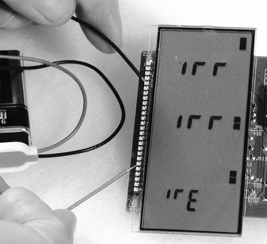
Figure 1 LCD elements being activated by direct battery connection.
You can animate the images by using the outputs of oscillators to blink the LCD elements instead of setting them “permanently” on with battery leads. Breadboard a simple oscillator with a 74C14; use a larger capacitor (2.2-10uf) and a big pot so it runs at a low, metronomic speed. Take one lead from the output of the oscillator one from the circuit ground (battery “–”). Connect the leads to points along the LCD edges that you know enable images (see figure 2). Adjust the oscillator speed and watch the LCD element turn on and off. If nothing happens, swap the oscillator output and ground connections to the LCD, or try different contact points. Continue to add more oscillators until you achieve the visual texture you want. When more than one oscillator is connected you can usually remove the ground lead from your circuit and just use oscillator outputs – the interaction amongst low and high outputs of the various oscillators activates the matrix. Alternatively you can connect jumpers between any electronic circuit (such as a bent toy) and contact points on a device containing an LCD screen and search for interesting modulation effects.
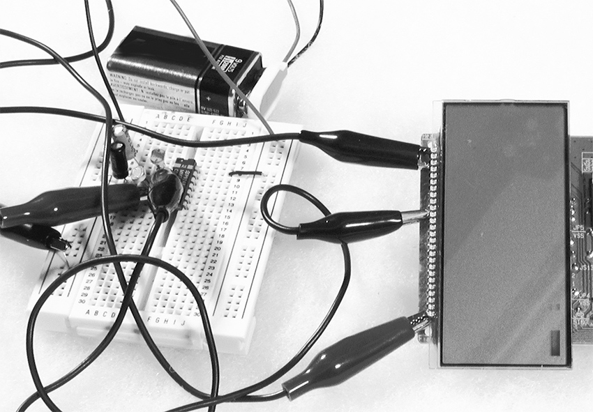
Figure 1 LCD elements animated by oscillator outputs.
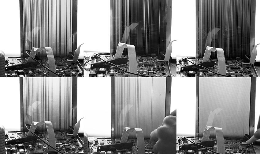
LCDs are kind of spooky—the image often lingers on the screen for several seconds after power is disconnected before fading out. The small screens bear a resemblance to old daguerreotypes (although Berlin artist Martin Riches reminds me that daguerreotypes had resolution so fine as to be discernable on a molecular level, in stark contrast to the crude pixilation of an LCD). They have a certain charm as modern miniatures, whether superimposed on new backdrops or left in their rather ghostly, mostly transparent state as tiny digital stained-glass windows. They are lovely hung in a sun-dappled cottage window.
The current consumption of the LCD device and a low-frequency oscillator is so small that you can leave the object running on a 9-volt battery for weeks before it runs down. You could even power the whole thing with a small solar panel (especially if you do choose to hang it in a sunny window). If you go shopping for the latter, look for one that puts out anywhere from 3 to 12 volts, with a current capacity of 5 milliamps or so. Some CMOS and LCD circuits can even be powered by a battery made from an apple or potato. So dust off those childhood science fair notes, or study the “Power Supplies” section of the Technical Bootcamp on this website for some alternative energy sources.
With a decent light source and the appropriate lens you can project your LCD onto a wall -- experiment with flashlights or bright LEDs and some lenses. Invest in one of those “third hand” devices: use the two articulated arms with alligator clips to hold the LCD and a lens to focus the image projected by a narrow-beam table lamp. You’ll have to remove any printed backdrop, of course, and some LCDs without a background picture use a simple self-adhesive reflective tape that must be peeled off to make them transparent.
You can also drop the LCD screens from tiny portable “stadium TVs” into older slideprojectors (see section on BMBCon in “Visual Music”). The screens of many older mini-TVs fortuitously have the same dimensions as a 35mm slide. You can do the same with the displays from many cheap hand-held games—the stupidest thumb-driven hockey match looks pretty cool projected huge, upside-down and slightly fuzzy on a wall. LCDs can be damaged by excessive heat – it helps to add additional fans to cool the slide well in the projector.
Don’t let the visual charm of LCDs distract you from their sonic potential. Clip the ground half of an audio cable to the battery ground of a working LCD circuit (before you do the hacks described above) and touch the hot lead to the various scan lines of the LCD display: you often hear deep, rich chords.
Higher Tech
Several companies specializing in high-end electronics toys, most notably V-Tech, make “video paint boxes” for children. These devices connect to a television and include a simple graphics tablet and keyboard with which the kid creates drawings and animations. Inside are some very sophisticated graphic chips that can be bamboozled into doing strange things. Following the technique described in “Beyond the Pot”, use wire or clip leads to interconnect any points on the circuit board. Occasionally you will get lucky and find connections that cause the graphics engine to freeze mid-way through drawing an image, re-color blocks of pixels, superimpose graphics from its memory, etc. Since these circuits usually use crystals for their clocks, any clock speed modification will probably require replacing the crystal with CMOS oscillator, as we discussed in chapter 15. And while you’re at it don’t forget to listen to different points on the board as well.
Culture & History
Do It With Others
Hardware Hacking in South America
Florencia Curci, Alma Laprida and Sebastián Rey
Translation by Jazmín Ortiz Ares
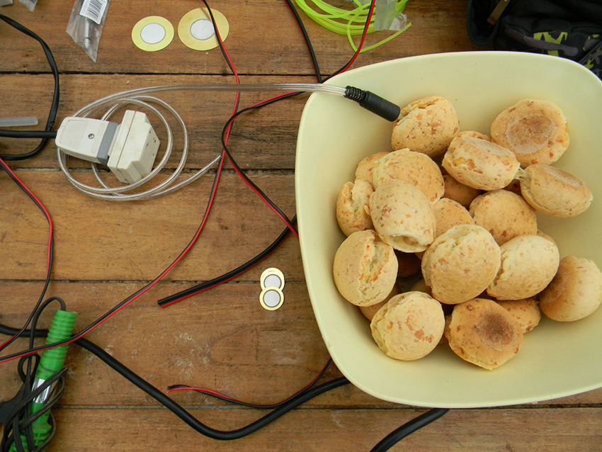
Figure 1 A bowl with chipá (a typical food from Paraguay and some regions of Argentina and Brazil) in a hardware hacking workshop. Photo © Sebastian Rey, used by permission.
Background
When invited to participate in the new edition of this book, we agreed that what interests us most, and what we want to make visible about hardware hacking, is the nature of meetings and networks that the activity fosters. In our individual experiences as artists, managers, educators and hackers living in Buenos Aires, we share a vision of what these encounters mean to us. For this overview of hacking culture in South America we reached out to self-identified hackers in Argentina, Bolivia, Brazil, Chile, Colombia, Ecuador and Peru, using a "snowball" or chain letter method in which artists invite other artists to participate.1 What follows are some observations from the information collected. Our intention was to track the networks that are born around hardware hacking and reveal those areas of “doing” that are not embodied in objects or works. Our text does not claim to be exhaustive, but rather to offer an account of a scene in vibrant ebullition and permanent change. We will give particular attention to cases in which hacking engages with growing feminist movements in South America.
From being being to being doing 2
For many, hardware hacking is rooted in finding alternative uses for existing devices—transforming a talking toy into an ominous synthesizer for example. For us, it means much more—a collective attitude that expands to create social and artistic networks.
For the last few years, the hacking virus increasingly infected Buenos Aires, fostering crossovers between disciplines and instigating research groups. We have observed three notable phenomena from our experiences in these activities. The first is the free circulation of information as an open source, to quote our friend Jorge Crowe. Information is shared to enhance the projects of others; it is not hidden or protected for personal profit.
The second is a pedagogical approach that contrasts with more traditional models in which it is assumed that to justify standing in front of a class, the teacher must know the subject matter thoroughly. Hacking revels in the potential that exists when teachers know only a little bit more about what they are teaching than the students. Our workshops generate communities of apprentices. Hacking hacks us, makes us use our ability to teach and learn in a different way and to foster new communities.3
The third characteristic of our scene is the frequent emergence, from workshops and other learning spaces, of new artistic groups and collectives. The energy released from newly acquired knowledge unfolds in new forms of aesthetic expression, but also in new means of production, performance and distribution. Buenos Aires has recently seen the emergence of groups such as Corpiños Luminosos y sus Guantes Sonoros (“Luminous Bras and their Sound Gloves”) and Aureola Electrika, audiovisual projects such as "Ludotecnia" and "Barbados", publishing labels such as MUN DISCOS, and collectives that work around education, art and technology such as Los Aparatos (“The Devices”) and SONIDOC!NICO (“Cynical Sound”)4.
We can think of hacking independent of hardware, as something we use to relate to others and to reconfigure our linkagess. We gather together to learn to solder and build an oscillator or an optical theremin, and to see how we can extract new expressiveness from an electronic toy. A stranger teaches us the differences between components in an electronics store. We exchange knowledge and experiences. We bring fresh air to our daily lives and we disrupt our status quo. What is more, we seem to be "breeding" our machines more than "creating" them.5
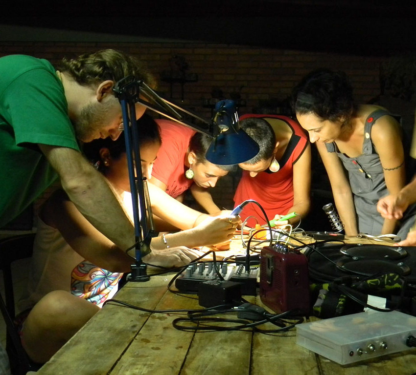
Figure 2 Students at a hardware hacking workshop in Puerto Libertad, Misiones, Argentina. Photo © Sebastian Rey, used by permission.
This process of constant doing is the essence of the hacker’s work, not as a means to reach a certain end, but as an end in itself. During the process we are forging ourselves and finding hints about how to continue walking the road. It is an open practice in which even mistakes can be included in the creative production. It is a practice of social emancipation.
Throwing a snowball at a network
To research hacking in South America we sent a kickoff questionnaire to some hackers we knew. We asked each person to answer some questions about their practice, send us a photo, and identify seven additional hackers. We then sent the same questionnaire to these new contacts, and each of them supplied the names of seven more hackers, and so on, and so on. We wanted to utlilize and reveal the affectionate bonding mechanism that is part of hardware hacking at a regional level.6
Several of our contacts associate hardware hacking with creative and critical action that helps us rethink the function of technology and things. Claudia González (Chile) defines it as "rebellion against the domain of knowledge," and maintains that "in Latin America it has always been done, with Third World economy things always end up hacked to give them new uses and to modify them." For OzZu ukumari (Bolivia), hardware hacking is "a way in which we have learned to cope and survive beyond transnational interests and the dominant thought of 'doing things correctly,' which prevails in West.” This hacker says that everyone, especially in Latin America, "has an integrated hacking chip" with which "we have learned to hack all technology and adapt it to our needs [...], it is the day by day, you use it to get free cable tv signal, you use it to modify the exhaust pipe of your car or motorcycle, to evade the ID of your IP."
In the same sense, Giuliano Obici (Brazil) argues that hacking is "a way of gambiarra," a Brazilian term for an informal and improvised way of solving a problem in the absence of proper resources or tools. This hacker and sound artist finds that both hacking and gambiarra "emerge from the need to keep a certain autonomy of the individual in the face of restrictive circumstances" and that both "point to the limitations of an instituted technical and/or ideological system and with that, its action can generate the collapse of the system, be it in a social, political or artistic way."7
We should emphasize that this appropriation of the concept of hacking has political implications and is anchored in the socioeconomic conditions of the region. Hackers position themselves as producers of technologies, and not as mere consumers.
Often in South America, hackers link with the community and with local practices. Many examples originate in education and local communities, such as "la Jaquer Escool," the education program of the Platohedro cultural center in experimental art and technology for young people (Medellín, Colombia), or the electromagnetism workshop for children in Montegrande (Chile) organized by Claudia Godoy.8 Sandra de Berduccy (A.K.A. Aruma), from Bolivia works with local ancestral practices, making weavings on traditional looms and incorporating circuitry, LEDs and speakers. She developed her research independently in rural locations and started hardware hacking "as a weaver, getting to know the depth, structures and processes of Andean tissues, and how energy works inside them."
Hacking technologies are not just electronic. A sort of biohacker, the Argentinian Ana Laura Cantera uses electronics and microorganisms, as she considers nature an interface. Her work Nidos de equilibrio (“Balance Nests”) uses energy generated by microbial cells, while her Utópicas reconstituciones (“Utopian Reconstituions”) uses physical structures created with mushrooms that she builds with GIY (Grow It Yourself) techniques.
Feminisms
Feminist movements have a long history in South America (and worldwide), but have become widespread and more visible in recent years. They usually have a pluralistic perspective and respond to a diversity of demands. They often link to local cultures and problems, and demonstrate different perspectives throughout the continent. In the last decade, feminism’s call was popularized by slogans that reached several previously divided social groups, and inspired them to join in globally growing movements. Massive demonstrations against feminicide and in support of Women's Day, mass campaigns to legalize free abortion, and groups of women demanding more participation and representation in different artistic, professional and political spaces, summoned large masses of women, lesbians and LGBTQ+.
In the work of the surveyed artists we found examples of feminist activism associated with hardware hacking, such as the performances of Corpiños Luminosos y sus Guantes Sonoros (Buenos Aires), a group of female hackers who wired bras with LEDs.9 The Colectivo 22bits (Santiago, Chile), an independent technofeminist group, runs workshops in electronics and "noise" for women. In 2018, they held a workshop on the construction of portable amplifiers installed in purses, backpacks and bags that were used to carry out a collective performance during the Women’s Day demonstration that year. Through the amplifiers, the women played sounds of past demonstrations in Chile. #VIVAS is a transnational collective based in Buenos Aires presenting feminist collaborative projects that began with the creation of a free open sound bank filled with interviews, poetry, conferences and field recordings of demonstrations. Over time it has expanded its scope, always linking to the affective use of technologies, adding multimedia workshops, production workshops and meeting spaces.
Figure 3 An image from a tutorial to make a luminous bra from Corpiños Luminosos y sus Guantes Sonoros. Photo © Carolina Andreeti, used by permission.
The Chilean hacker Constanza Piña (A.K.A. Corazón de Robota) has created clothes and accessories with electronics, and blogs step-by-step instructions on how to create a homemade feminine pad, "My blood is my revolution".10 With Claudia Gonzalez she founded ChimbaLab, one of the first entirely female medialabs.
Conclusions
We started our research by positing hardware hacking as a practice of free circulation of information, as a non-formal pedagogical approach and as a contagious energy that can be the basis for collective projects. The results from our survey surpassed our expectations. Through it we discovered hackers and artists who develop work with a playful and creative spirit. We found and shared some deep and lucid reflections. It's exciting to see how hacking is embedded in context: it thrives on local and regional experiences, it takes "data" from, and dialogues with, very old practices, and it embodies contemporary feminist activism.
We also note that in South America the reuse and resignification of materials considered obsolete is not merely an aesthetic decision, but a political one. In contrast with an economic model that defines wealth as the accumulation of money and new objects, in our local cultures, wealth is often linked to the management of one's own time, of being together, and of reorganizing materials so that they are better adapted for our own purposes. We can think of hacking in the South America as a collective practice that spreads like a virus, that generates networks, that relates intimately to the economic and political situations of the region, and through which we question old inherited models of ourselves in relation to each other and our possessions.
We stop thinking about a definition of hacking based on its technical specificity, and we ask ourselves how the practice of hacking can make systems transform for the better.
The piezoelectric revolution is an eternal dream.
Figure 4 A piezoelectric mic hangs from a wire for hanging clothes in Montevideo, Uruguay. Notice the faint poster of Che Guevara in the back. Photo © Sebastian Rey, used by permission.
Consulted texts and links
Alonso, R. (2015). Elogio de la low tech. Historia y estética de las artes electrónicas en América Latina. Buenos Aires: Luna Editores.
Cambiasso, N. (2010). Breve panorama de la experimentación latinoamericana
actual. Experimentaclub LIMb0: Proyecto iberoamericano de intercambio artístico y cooperación cultural. Buenos Aires: Experimentaclub LIMb0.
Campos Fonseca, S. (2013). Giro decolonial y estética. Algunas consideraciones. Available at: https://www.academia.edu/3345739/Giro_decolonial_y_est%C3%A9tica_algunas_consideraciones
Campos Fonseca, S. (2016). Ciberfeminismo y Estudios sonoros. Available at:
https://www.academia.edu/27049036/Ciberfeminismo_y_estudios_sonoros
Retrieved on May 24, 2019.
Cantera, A. L. (n.d). Nidos de equilibrio. Available at:
https://analauracantera.wordpress.com/2018/01/31/nidos-de-equilibrio/
Retrieved on May 23, 2019.
Cantera, A. L. (n.d.). Utópicas reconstituciones. Available at:
https://analauracantera.wordpress.com/2018/02/02/utopicas-reconstituciones/
Retrieved on May 23, 2019.
Cantú, M. (2011). Espacios autogestionados y Artes Mediáticas en Argentina. Available at: https://marielacantu.wordpress.com/articulos/espacios-autogestionados-y-artes-mediaticas-en-argentina/
Retrieved on May 2, 2019.
Castro, J. (2010). La rebelión de los neutrales. Hacklabs en Latinoamérica. Errata.
Cultura Digital Nro. 3. Páginas 224-227. Available at:
https://issuu.com/revistaerrata/docs/errata_3_cultura_digital_creaci_n
Retrieved on May 23, 2019.
Gálvez, A. (2009). Las huelgas del 8M en América Latina. Revista Contexto.
Available at: https://ctxt.es/es/20190313/Politica/24901/Andrea-Ana-Galvez-feminismo-manifiesto-america-mujeres-trans-lesbianas-travestis.htm
Retrieved on
May 22, 2019.
Gontijo, J. (2014). Distopías tecnológicas. Rio de Janeiro: Editora Circuito.
Available at: http://arteymedios.org/biblioteca/publicaciones/item/349-distopias-tecnologicas.
Retrieved on May 23, 2019.
Haraway, D. (1984). Manifiesto Ciborg. El sueño irónico de un lenguaje común para
las mujeres en el circuito integrado. Available at:
https://xenero.webs.uvigo.es/profesorado/beatriz_suarez/ciborg.pdf.
Retrieved on May 24, 2019.
Krochmalny, S. (2008). Tecnologías de la amistad. Las formas sociales de
producción, gestión y circulación artística en base a la amistad. Available at:
http://www.ramona.org.ar/node/21668.
Retrieved on May 23, 2019.
Kusch, R. (2007). La negación en el pensamiento popular. In Obras Completas,
Tomo II. Páginas Rosario: Editorial Fundación Ross.
McLuhan, M. y Fiore, Q. (1987). El medio es el masaje. Un inventario de efectos.
Buenos Aires: Ediciones Paidós.
McLuhan, M. (2015). Inédito. Buenos Aires: La Marca Editora.
Molina, B. y Serrano, M. (2018). Portafolio del Colectivo de arte y tecnología 22bits.
Trabajo seleccionado año 2016 a 2018. Available at:
https://www.docdroid.net/N2QpoQW/dossier2019.pdf#page=16
Retrieved on May 2, 2019.
Obici, G. (2014). Gambiarra e experimentalismo sonoro. Available at:
http://www.giulianobici.com/site/archives/2014GambiarraExperimentalismoSonoro.pdf.
Retrieved on May, 2019.
Obici, G. (n.d.). Gambioluthery. Revisiting the musical instrument from a Bricolage perspective. Available at:
http://www.giulianobici.com/site/archives/2017LMJ27GambioluthieryObici.pdf
Retrieved on May 23, 2019.
Piña, C. (2011-2015). Tutoriales. Available at:
https://corazonderobota.wordpress.com/category/tutoriales/
Retrieved on May 23, 2019.
Ranciere, J. (2018). El maestro ignorante. Cinco lecciones sobre la emancipación
intelectual. Buenos Aires: Edhasa.
Rodríguez, H. (2016). SubalterNet: Networked Practices from Latin America in
Response to the Internet. Media-N. V. 12 Nro. I. Available at:
http://median.newmediacaucus.org/mestizo-technology-art-design-and-technoscience-in-latin-america/subalternet-networked-practices-from-latin-america-in-response-to-the-internet/.
Retrieved on May 23, 2019.
Tarducci, M. (2018). Escenas clave de la lucha por el derecho al aborto en
Argentina. Salud Colectiva. V 14 Nro. III. Available at:
https://www.scielosp.org/article/scol/2018.v14n3/425-432/es/
Retrieved on May 24, 2019.
Trilnik, C. (n.d.). Manifiesto antropofágico. Available at:
https://proyectoidis.org/manifiesto-antropofago/
Retrieved on May 2, 2019.
de Ugarte, D. (n.d.). El poder de las redes. Manual ilustrado para personas,
colectivos y empresas abocados al ciberactivismo. Available at:
http://www.pensamientocritico.org/davuga0313.pdf.
Retrieved on May 23, 2019.
Acknowledgements
We want to thank Casa Tomada, CASo, Jorge Crowe, Luciana Fleischman, Soledad Tuñón and all the artists who answered our survey.
1 We based our method on that of the Argentine website "Bola de nieve" (http://www.boladenieve.org.ar/, recovered on May 18, 2019), a project of the visual arts magazine Ramona and the Start Foundation, to create profiles of artists who are invited to answer a series of questions about their practices after being identified by other participating artists
2 “To be being" (estar siendo) is a concept proposed by the Argentine philosopher Rodolfo Kusch, who talks about a way of thinking rooted in Latin America. We propose a wordplay between the ideas of Kusch and the "doing" of hacking.
3 We can associate this idea with McLuhan's concept of environments and anti-environments. He argues that it is important to design a new environment and leave the content free: this is the logic of the anti-environment, in contrast to the ambient. We understand the space of hacking as an anti-environment, as it contains logics that differ from the traditional ones: it allows us to question inherited ways of teaching and learning, of appropriation of spaces and of use of tools and materials.
4 There is a second meaning in the use of the term “cinico (“cynical”) as an acronym for Circuito Independiente de Iniciativas Caseras Organizadas, ("Independent Circuit of Organized Homemade Inictiatives)
5 This idea was articulated by Valeria González, who sees the verb "creating" (crear, in Spanish) as linked to the male creator and individual, in opposition to "breeding" (criar), which she uses to refer to a cooperative or family and mutual work learning.
6 We are interested in the work on "friendship technologies" that Syd Krochmalny (2008) talks about.
7 See also his essay, “Gambiarra: Hacking and DIY in Brazil”, in this section of the website.
8 Claudia Godoy made an interesting artist's book from documentation of the workshop: https://www.claudiagonzalez.cl/publicaciones-all/bitacora-taller-de-campo-magnetico-en-montegrande / (retrieved on May 23, 2019).
9 It is relevant to mention the work of Campos Fonseca (2006, from Costa Rica) on Cyberfeminism, in which she defines it as "a cooperation practice between women, machines and new technologies."
10 https://corazonderobota.wordpress.com/2015/06/29/my-blood-is-my-revolution/ (Retrieved on May 23, 2019).
Hacer Con Otrxs
Hardware Hacking en Sudamérica (Florencia Curci, Alma Laprida and Sebastián Rey)
Por Florencia Curci, Alma Laprida y Sebastián Rey
Traducción al inglés por Jazmín Ortiz Ares
Figura 1 Un bol con chipá (una comida típica de Paraguay y algunas regiones de Argentina y Brasil) en un taller de hardware hacking
Antecedentes
Al recibir la invitación para participar de la nueva edición de este libro, pensamos que lo que más nos interesa y lo que queremos visibilizar acerca del hardware hacking es el tipo de encuentros y la red de conexiones que propicia. En nuestras experiencias individuales como artistas, gestorxs, educadorxs y hackers que viven en la Ciudad de Buenos Aires, compartimos una visión similar en cuanto a lo que significan estas prácticas y estos encuentros. Para construir esta mirada general sobre la cultura hacker en Sudamérica, contactamos a hackers de Argentina, Bolivia, Brasil, Chile, Colombia, Ecuador y Perú con el método de la “bola de nieve” 1 e hicimos algunas observaciones a partir de la información relevada. Nuestra intención fue rastrearlas redes que nacen en torno al hardware hacking y revelar aquellas zonas del hacer que no están plasmadas en objetos u obras. En este sentido, el artículo no pretende ser exhaustivo sino dar cuenta de un panorama en plena ebullición y cambio permanente. Mencionaremos algunos casos en los cuales el hacking se articula con un fenómeno que está creciendo en América del Sur: los feminismos.
De estar siendo a estar haciendo2
Para muchxs, la definición de hardware hacking consiste en encontrar otros usos posibles para aparatos ya existentes: por ejemplo, transformar un juguete que habla en un sintetizador monstruoso. Para nosotrxs significa mucho más: un pensar colectivo que se despliega en espacios y modos de encuentro y se convierte en redes.
Hace unos años que el virus del hacking se contagia cada vez más en Buenos Aires, propicia cruces entre disciplinas y establece núcleos de investigación. Nos interesan particularmente tres fenómenos que observamos a partir de nuestras experiencias personales en los talleres y laboratorios de hacking. El primero de ellos es la circulación de información, libre, como un código abierto (así dice nuestro amigo Jorge Crowe). La data se comparte para potenciar proyectos afines al propio: no se la oculta ni restringe.
El segundo es un posicionamiento en la prácticas pedagógicas que contrasta con los modelos tradicionales en los cuales se piensa que, para estar al frente de una clase, lx docente debe conocer a fondo el proceso y los materiales con los que trabaja. El hacking evidencia la potencia que existe en crear espacios de investigación acerca de un tema del cual lx docente sólo sabe un poco. De este modo, generamos comunidades de aprendices. El hacking nos hackea, hace un uso diferente de nuestra capacidad de enseñar y aprender, de dar clases y de generar espacios de encuentro 3.
La tercera característica de nuestra escena es la frecuencia con la que surgen nuevos grupos y colectivos sonoros y/o performáticos en talleres y otros espacios de aprendizaje. La energía liberada a partir de los encuentros se despliega y alcanza nuevas formas de expresión estética. En Buenos Aires, hemos visto surgir grupos con un trabajo muy potente como ''Corpiños luminosos y sus guantes sonoros'' y ''Aureola Electrika”, proyectos audiovisuales como ''Ludotecnia'' y ''Barbados'', sellos editoriales como MUN DISCOS y colectivos que trabajan en torno a la educación, el arte y la tecnología como ''Los aparatos'' y ''SON!DOCINICO4".
Podemos pensar el hardware hacking como una terceridad, algo que usamos para relacionarnos con otrxs y que permite reconfigurar nuestros modos de vincularnos. Nos juntamos a aprender a soldar y construir un oscilador o un theremin óptico o a ver cómo podemos encontrar nuevos modos expresivos a partir de los sonidos de un juguete. Unx desconocidx nos enseña las diferencias entre componentes en una casa de electrónica. Cruzamos saberes y experiencias. Liberamos algo de oxígeno en lo cotidiano y dislocamos nuestro status quo. Más que “crear” nuestras máquinas, las criamos5.
Figura 2 Comunidad de aprendices en un taller de hardware hacking en Puerto Libertad, Misiones, Argentina.
Queremos rescatar el proceso permanente de estar haciendo como esencia de la labor hacker. No como un medio para llegar a un fin determinado, sino como un fin en sí mismo. Durante el proceso vamos forjándonos y encontrando pistas acerca de cómo continuar el camino. Es una práctica abierta en la cual el error es parte de la producción creativa. Es una práctica social de emancipación.
Una bola de nieve para evidenciar una red
Para investigar hacking en Sudamérica enviamos un cuestionario como puntapié a algunxs hackers que conocíamos. Le pedimos a cada persona que conteste algunas preguntas sobre su práctica, que nos envíe una foto, un link y que mencione a otrxs siete hackers. Después le enviamos el mismo cuestionario a estos nuevos contactos y ellxs nos dieron los nombres de siete más, y así, y así. Queríamos representar y evidenciar un mecanismo de vinculación afectuosa6 que es parte del hardware hacking a nivel regional.
Varixs de lxs hackers consultados asocian el hardware hacking con una acción creativa y crítica, que permite repensar la función de la tecnología y de las cosas en general. Claudia González (Chile) lo define como “rebeldía hacia el dominio del conocimiento”, y sostiene que “en Latinoamérica se ha realizado siempre, con una economía de tercer mundo las cosas siempre terminan hackeadas para darles nuevos usos y para modificarlas”. Para OzZu ukumari (Bolivia), hardware hacking es ”una forma en que hemos aprendido a sobrellevar y sobrevivir más allá de los intereses transnacionales y, por supuesto, del pensamiento dominante de ‘hacer las cosas correctamente’, que impera en occidente”. Este hacker sostiene que todxs, y especialmente en Latinoamérica, “tenemos un chip integrado de hacking” con el cual “hemos aprendido a piratear toda la tecnología y adaptarla a nuestras necesidades [...], es el día a día, lo utilizas para captar más señales de tv cable pago, lo utilizas para modificar el caño de escape de tu auto o moto, para evadir el ID de tu IP”.
En el mismo sentido, Giuliano Obici (Brasil) sostiene que el hacking es “una forma de gambiarra”, una manera informal e improvisada de resolver un problema ante la falta de recursos o herramientas. Este hacker y artista sonoro encuentra que tanto el hacking como la gambiarra son acciones “que emerge[n] de la necesidad de mantener viva cierta autonomía del individuo ante circunstancias restrictivas” y que ambos “apuntan a las limitaciones de un sistema técnico y/o ideológico instituido y con eso, su acción puede generar el colapso del sistema, sea social, político o artístico”.
Queremos destacar que esta apropiación del concepto de hacking tiene implicancias políticas y un anclaje en las condiciones socioeconómicas de la región. Lx hacker se posiciona como unx productorx de tecnologías y no como unx merx consumidorx.
Nos interesa también mencionar algunas prácticas en las cuales el hacking en Sudamérica se vincula con la comunidad y con prácticas locales. Los ejemplos más numerosos de esto tienen que ver con el trabajo en educación y territorio, como “la Jaquer Escool”, la línea de formación del centro cultural Platohedro en “arte experimental y tecnología” para jóvenes (Medellín). O el taller de electromagnetismo dirigido a niñxs de Montegrande (Chile) de Claudia Godoy7. Sandra de Berduccy (A.K.A. Aruma, de Bolivia), por ejemplo trabaja a partir de prácticas ancestrales locales. Sandra realiza telares tradicionales en los cuales incorpora electrónica, leds y parlantes. Lleva sus investigaciones de manera independiente en espacios rurales y dice que se inició en el hardware hacking “como tejedora, conociendo a profundidad las estructuras y los procesos de los tejidos andinos, y cómo opera la energía dentro de ellos”.
Las tecnologías del hacking no son sólo electrónicas. La argentina Ana Laura Cantera utiliza la electrónica y microorganismos para considerar la naturaleza como interfaz, como una suerte de biohacker. En su obra “Nidos de equilibrio” utiliza energía generada por celdas microbianas y en “Utópicas reconstituciones” utiliza estructuras creadas con hongos que construyó con técnicas GIY (Grow It Yourself).
Feminismos
Los movimientos feministas, si bien tienen una larga trayectoria en Sudamérica (y a nivel mundial), se masificaron en los últimos años. Suelen tener una mirada pluralista y responden a demandas diversas e interseccionales. Están ligados a territorios y problemáticas locales y demuestran diferentes perspectivas a lo largo y ancho de la región. En la última década, no obstante, su convocatoria se popularizó al movilizar consignas que interpelaron a varios actores sociales antes divididos, lo que acompañó el crecimiento generalizado de los movimientos a nivel mundial. Marchas multitudinarias en contra del feminicidio y en el día de la mujer, campañas masivas a favor del aborto legal y gratuito y agrupaciones de mujeres exigiendo más participación y representación en distintos espacios artísticos, profesionales y políticos, convocaron grandes masas de mujeres, lesbianas y disidencias (LGBTQ+).
En el quehacer de algunxs artistxs relevadxs encontramos ejemplos de activismo feminista asociado al hardware hacking8, como las performances de “Corpiños luminosos y los guantes sonoros” (Buenos Aires), una agrupación integrada por mujeres hackers que intervinieron una prenda femenina y la convirtieron en un gesto irreverente. El Colectivo 22bits, de Santiago de Chile, se define como “una agrupación independiente y tecnofeminista” que, entre otras acciones, dicta talleres de iniciación a la electrónica y al “ruido” dirigidos a mujeres. En 2018, realizaron un taller de construcción de amplificadores portátiles instalados en carteras, mochilas y bolsos que fueron utilizados para realizar una acción artística colectiva en la marcha del 8 de marzo de ese año. A través de los amplificadores, las mujeres reprodujeron sonidos de manifestaciones antiguas de Chile. #VIVAS, por su parte, es un colectivo transnacional con base en Buenos Aires de manifestaciones colaborativas feministas que se inició con la creación de un banco de sonidos abierto y de uso libre de registros de marchas, entrevistas, poesías y conferencias. Luego amplió su accionar, siempre ligado a la utilización afectiva de tecnologías, con talleres multimediales, jornadas de producción y espacios de charla y encuentro.
Figura 3 Imagen de un tutorial para hacer un corpiño intervenido del colectivo Corpiños Luminosos y sus Guantes Sonoros.
La también chilena Constanza Piña (A.K.A. Corazón de Robota), hacker que desarrolló gran parte de su trabajo en torno a la creación de indumentaria y accesorios con electrónica, tiene entre los tutoriales de electrónica blanda de su blog un paso a paso con imágenes de cómo crear una toallita femenina casera9, titulado “My blood is my revolution”. Además, fundó junto a Claudia González el ChimbaLab, un medialab íntegramente femenino.
Conclusiones
Comenzamos el artículo hablando del hardware hacking como una práctica de libre circulación de información, como una práctica pedagógica distinta a los modelos tradicionales y como una energía contagiosa que puede ser base para proyectos colectivos. Los resultados del relevamiento han superado enormemente nuestras expectativas. A través de él descubrimos hackers y artistas que desarrollan sus trabajos con un espíritu lúdico y creador. También encontramos y compartimos reflexiones profundas y lúcidas. Es emocionante ver cómo el hacking está imbricado en sus contextos: se nutre de experiencias locales y regionales, toma data de y dialoga con prácticas muy antiguas y se encarna en activismo feminista.
También notamos que la reutilización y resignificación de materiales considerados obsoletos no es una decisión que surge solamente desde lo estético sino que encuentra en Sudamérica un posicionamiento político muy claro. En contraste con una organización económica en la cual la riqueza se define como la acumulación de dinero y objetos nuevos, aquí la idea de riqueza se vincula con la gestión del tiempo propio, el estar juntos y la reorganización de materiales para que sean funcionales a nuestros fines. Hackear nos posiciona como productorxs de tecnologías y no como merxs consumidorxs. Podemos pensar al hacking en Sudamérica como una práctica colectiva que se propaga como un virus, que genera redes y que está íntimamente relacionada con la coyuntura económica y política de la región, mediante la cual ponemos en discusión viejos modelos heredados de relacionarnos y de conocernos.
Dejamos de pensar en una definición del hacking basada en su especificidad técnica para preguntarnos de qué modo la práctica del hacking puede hacer colapsar los sistemas.
La revolución piezoeléctrica es un sueño eterno.
Figura 4 Un micrófono piezoeléctrico cuelga de un cable utilizado para colgar la ropa en Montevideo, Uruguay. En la pared se observa un poster descolorido del Che Guevara.
Textos y links consultados
- Alonso, R. (2015). Elogio de la low tech. Historia y estética de las artes electrónicas en América Latina. Buenos Aires: Luna Editores.
- Cambiasso, N. (2010). Breve panorama de la experimentación latinoamericana actual. Experimentaclub LIMb0: Proyecto iberoamericano de intercambio artístico y cooperación cultural. Buenos Aires: Experimentaclub LIMb0.
- Campos Fonseca, S. (2013). Giro decolonial y estética. Algunas consideraciones. Disponible en: https://www.academia.edu/3345739/Giro_decolonial_y_est%C3%A9tica_algunas_consideraciones
- Campos Fonseca, S. (2016). Ciberfeminismo y Estudios sonoros. Disponible en: https://www.academia.edu/27049036/Ciberfeminismo_y_estudios_sonoros Recuperado el 24 de mayo de 2019.
- Cantera, A. L. (sin fecha). Nidos de equilibrio. Disponible en: https://analauracantera.wordpress.com/2018/01/31/nidos-de-equilibrio/ Recuperado el 23 de mayo de 2019.
- Cantera, A. L. (sin fecha). Utópicas reconstituciones. Disponible en: https://analauracantera.wordpress.com/2018/02/02/utopicas-reconstituciones/ Recuperado el 23 de mayo de 2019.
- Cantú, M. (2011). Espacios autogestionados y Artes Mediáticas en Argentina. Disponible en: https://marielacantu.wordpress.com/articulos/espacios-autogestionados-y-artes-mediaticas-en-argentina/. Recuperado el 2 de mayo de 2019.
- Castro, J. (2010). La rebelión de los neutrales. Hacklabs en Latinoamérica. Errata. Cultura Digital Nro. 3. Páginas 224-227. Disponible en: https://issuu.com/revistaerrata/docs/errata_3_cultura_digital_creaci_n Recuperado el 23 de mayo de 2019.
- Gálvez, A. (2009). Las huelgas del 8M en América Latina. Revista Contexto. Disponible en: https://ctxt.es/es/20190313/Politica/24901/Andrea-Ana-Galvez-feminismo-manifiesto-america-mujeres-trans-lesbianas-travestis.htm Recuperado el 22 de mayo de 2019.
- Gontijo, J. (2014). Distopías tecnológicas. Rio de Janeiro: Editora Circuito. Disponible en: http://arteymedios.org/biblioteca/publicaciones/item/349-distopias-tecnologicas. Recuperado el 23 de mayo de 2019.
- Haraway, D. (1984). Manifiesto Ciborg. El sueño irónico de un lenguaje común para las mujeres en el circuito integrado. Disponible en: https://xenero.webs.uvigo.es/profesorado/beatriz_suarez/ciborg.pdf. Recuperado el 24 de mayo de 2019.
- Krochmalny, S. (2008). Tecnologías de la amistad. Las formas sociales de producción, gestión y circulación artística en base a la amistad. Disponible en: http://www.ramona.org.ar/node/21668. Recuperado el 23 de mayo de 2019.
- Kusch, R. (2007). La negación en el pensamiento popular. En Obras Completas, Tomo II. Páginas Rosario: Editorial Fundación Ross.
- McLuhan, M. y Fiore, Q. (1987). El medio es el masaje. Un inventario de efectos. Buenos Aires: Ediciones Paidós.
- McLuhan, M. (2015). Inédito. Buenos Aires: La Marca Editora.
- Molina, B. y Serrano, M. (2018). Portafolio del Colectivo de arte y tecnología 22bits. Trabajo seleccionado año 2016 a 2018. Disponible en: https://www.docdroid.net/N2QpoQW/dossier2019.pdf#page=16 Recuperado el 2 de mayo de 2019.
- Obici, G. (2014). Gambiarra e experimentalismo sonoro. Disponible en: http://www.giulianobici.com/site/archives/2014GambiarraExperimentalismoSonoro.pdf. Recuperado el 23 de mayo de 2019.
- Obici, G. (sin fecha). Gambioluthery. Revisiting the musical instrument from a Bricolage perspective. Disponible en: http://www.giulianobici.com/site/archives/2017LMJ27GambioluthieryObici.pdf Recuperado el 23 de mayo de 2019.
- Piña, C. (2011-2015). “Tutoriales”. Disponible en: https://corazonderobota.wordpress.com/category/tutoriales/ Recuperado el 23 de mayo de 2019.
- Ranciere, J. (2018). El maestro ignorante. Cinco lecciones sobre la emancipación intelectual. Buenos Aires: Edhasa.
- Rodríguez, H. (2016). SubalterNet: Networked Practices from Latin America in Response to the Internet. Media-N. V. 12 Nro. I. Disponible en: http://median.newmediacaucus.org/mestizo-technology-art-design-and-technoscience-in-latin-america/subalternet-networked-practices-from-latin-america-in-response-to-the-internet/. Recuperado el 23 de mayo de 2019.
- Tarducci, M. (2018). Escenas clave de la lucha por el derecho al aborto en Argentina. Salud Colectiva. V 14 Nro. III. Disponible en: https://www.scielosp.org/article/scol/2018.v14n3/425-432/es/ Recuperado el 24 de mayo de 2019.
- Trilnik, C. (sin fecha). Manifiesto antropofágico. Disponible en: https://proyectoidis.org/manifiesto-antropofago/ Recuperado el 2 de mayo de 2019.
- de Ugarte, D. (sin fecha). El poder de las redes. Manual ilustrado para personas, colectivos y empresas abocados al ciberactivismo. Disponible en: http://www.pensamientocritico.org/davuga0313.pdf. Recuperado el 23 de mayo de 2019.
Agradecimientos
Queremos agradecer a Casa Tomada, CASo, Jorge Crowe, Roger Colom, Luciana Fleischman, Soledad Tuñón y a todos los artistas que contestaron nuestro formulario.
1 Para realizar un relevamiento de hackers que evidencie las redes de contactos entre ellxs, nos basamos en el método de la página web argentina “Bola de nieve” (http://www.boladenieve.org.ar/, recuperada el 18 de mayo de 2019), un proyecto de la revista de artes visuales Ramona y la Fundación Start, en la cual se crean perfiles de artistas que son invitadxs a responder una serie de preguntas sobre sus prácticas luego de ser nombradxs por otrxs artistas participantes.
2 “Estar siendo” es un concepto propuesto por el filósofo argentino Rodolfo Kusch, quien habla de una forma de pensar enraizada en Latinoamérica. Proponemos un juego de palabras entre las ideas de Kusch y el “hacer” del hacking.
3 Podemos asociar esta idea al concepto de ambientes y antiambientes de McLuhan. Este autor habla de que estamos habituados a ambientes indetectables. Para él, es más importante diseñar un nuevo ambiente y dejar libre el contenido: esta es la lógica del antiambiente, que contrasta con la del ambiente. Nosotrxs entendemos el espacio del hacking como un antiambiente en tanto contiene lógicas distintas al de los espacios educativos tradicionales: nos permite poner en jaque modos heredados de enseñar y aprender, de apropiarnos de los espacios y modos de uso de las herramientas y materiales.
4 “C.I.N.I.C.O” aquí es un acrónimo de “Circuito Independiente de Iniciativas Caseras Organizadas”.
5 Tomamos esta idea de Valeria González, quien opone el concepto de “crear”, vinculado al creador masculino e individual, en contraposición con “criar”, que refiere a las tareas del cuidado, el trabajo cooperativo, familiar, y de mutuo aprendizaje.
6 Nos interesa el trabajo sobre “tecnologías de la amistad” de la que habla Syd Krochmalny (2008).
7 Claudia tiene un interesante libro de artista realizado a partir de la documentación del taller, disponible en: https://www.claudiagonzalez.cl/publicaciones-all/bitacora-taller-de-campo-magnetico-en-montegrande/(recuperado el 23 de mayo de 2019).
8 Es relevante mencionar el trabajo de Campos Fonseca (2006, desde Costa Rica) sobre ciberfeminismo, en el que lo define como “una práctica de cooperación entre mujer, máquina y nuevas tecnologías”.
9 https://corazonderobota.wordpress.com/2015/06/29/my-blood-is-my-revolution/ (Recuperado el 23 de mayo de 2019).
Bleep Listening
Ezra Teboul
Handmade electronic music can be thought of as the coordinated production of electronic instruments and electronic sound. An exploration of the "music implicit in technology,"1 it requires attention to the electrical properties of materials, to the sonic consequences of those materials’ evolving interconnections, and to the creation of situations favorable to the exploration of those evolutions. Therefore, any study of the practice should consider both the assembled and the assembler: who and what share responsibility for the resulting ever-changing communities and artifacts?2
The listening associated with hardware hacking focuses on the musical potential of electronics as they operate. This often results in a collapse of the distance that traditionally distinguished the musical score from the instrument: this led Alvin Lucier to consider the viability of the circuit as a score.3 The practice of hardware hacking has continued to build institutional and popular legitimacy as a method of musical composition and creative work, while embracing a fragmented and shapeshifting type of material production.
The standardization of electronic components and industrial practices means that most practitioners are linked, consciously or not, to global production processes. This connection is mirrored in global patterns of consumption, and both phenomena are enacted by the unequal, global connecting tissue of the Internet. Since the publication of the earlier editions of this book, a thousand fuzztones have indeed flowered thanks to Tim Berners-Lee;4 this was quickly replicated ad infinitum for almost every other effect, synthesizer and controller imaginable. Hacking has only gotten easier (ibid) -- so much so that each electronic music genre now has its own subculture of fetishizing, criticizing and developing or ignoring technological tools. Larger manufacturers monitor potential markets through the public platforms that propagate these do-it-yourself and do-it-together projects, and respond by producing variations of old, nostalgic favorites on a regular basis - for a premium.5 This continues the cycle of over-production, cannibalization and adaptation that fostered hacking practice in the first place.
Tara Rodgers reminds us that none of these instruments are made in a vacuum, and that each instance of handmade electronic music is an opportunity to think about how online and off-line resources have led to the development of temporary, erratic, ad-hoc groups.6 The conditions specific to each project—available parts, information, ideas, individuals—shape the final results. This dynamic process is, however, is not well-documented.7 Recovering the labor and paths of knowledge in the making of handmade electronic music has become a mission for a number of individuals, online communities and academic subdisciplines, who grapple in different ways with the friction between global technological commodities and small-scale art practices.8
Handmade Electronic Music did not explicitly ask how hacking communities emerged (it was not a sociological study), but it did offer a peek into the extensive body of work these efforts have produced, from the point of view one of the field’s participants. The categories used in the book to distinguish meaningful technological sub-trends—circuit bending, feedback, battery-powered, bands, audiovisual, mechanical, circuits from scratch—reflected the author’s experiences and perspective. The inclusion of a variety of new authors in this third edition is an acknowledgement of the breadth of contemporary activity. In this chapter I discuss recent projects, some of which fit Collins’s earlier categories, while others require new groupings to accommodate their inspirations and aspirations.9
Chaos
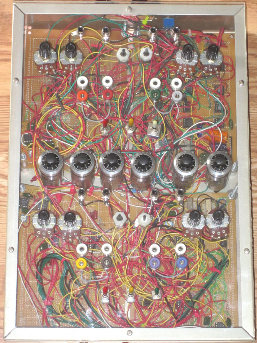
Figure 1 David Dunn, Thresholds and Fragile States. Device and corresponding block diagram for the first half of the circuit (second half is a mirror copy). Images courtesy of the artist.
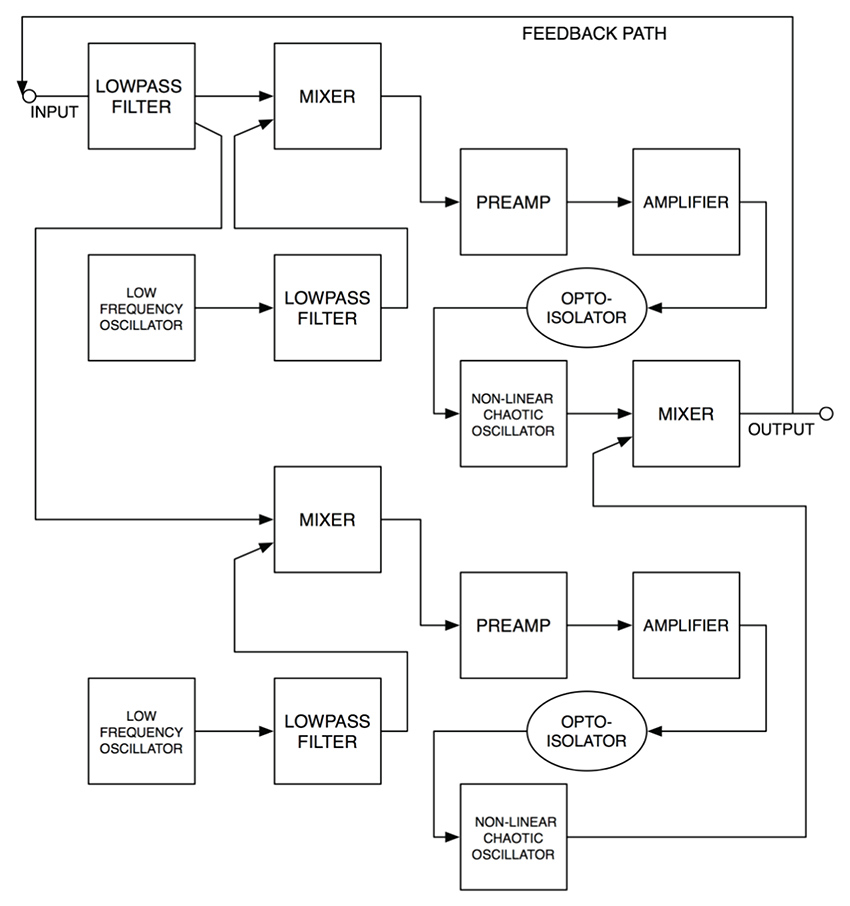
David Dunn is among a number of musicians interested in chaotic behavior in sonic contexts. His Thresholds and Fragile States (2010-2011) is a synthesizer built around a network of four chaotic "jerk" oscillators.10 He was inspired by listening to the "emergent logic" of shifting sonic balances in Louisiana's Atchafalaya basin, and describes the work as "an attempt at understanding pattern formation in natural sound systems."11 The unpredictable nature of the circuit, which cannot be “controlled” so much as “oriented,” is reflective of a longstanding trend in experimental electronic instrument design to foreground rather than minimize chaotic patterns. Dunn works between the scale of his sonic environment and that of his handmade electronic system, listening to both so one can inform his experience of the other. This type of generative electronic system behavior, which Dunn calls "autopoiesis," has precedents in instruments such as in Salvatore Martirano's Sal-Mar Construction12 and David Tudor's feedback network compositions.13
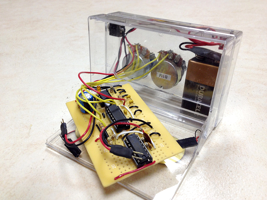
Figure 2 One of Blonda's Chaos Boxes, built from two clear cassette tape enclosures. Photo courtesy of the artist.
David Kant, a student of Dunn's, has expanded on this tradition of chaotic hardware with a software model of Dunn's circuits for the audio programming language Supercollider.14 He had earlier built circuits with Madison Heying for their duo, Blonda, including a set of nonlinear feedback circuits based on the 4046 phase-locked loop integrated circuit (see Chapter 23) which exhibited chaotic behaviors. In their iteration of the 4046 circuit, the input and the output of each Chaos Box are routed to piezoelectric discs, both attached to the surface of the enclosures. Blonda performs by manipulating both the control knobs and the boxes themselves—hitting, scrubbing, scraping and otherwise using these enclosures as resonant bodies. In a process not dissimilar to Dunn's use of the Thresholds and Fragile States system, Heying and Kant listen to the patterns that emerge between these electrical and acoustical feedback paths, as mediated by the phase-locked loops, in an attempt to direct the devices roughly down the musical paths they wish to go.15
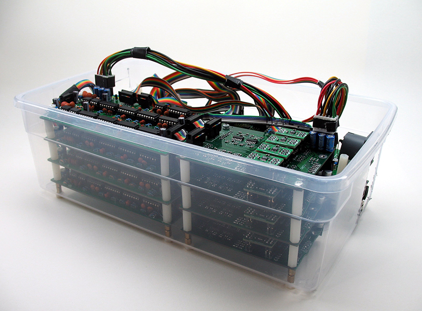
Figure 3 Part of Philip White's Feedback Instrument. The system includes a number of other modules. Photo courtesy of the artist.
You Nakai’s and Michael Johnsen’s 2016 paper on David Tudor's Untitled (1972) and Toneburst (1975) inspired composer Philip White to update an earlier mixer-based feedback system for use in his Feedback Instrument(2017). Drawing on accounts of Tudor's electronics experiments, as well as on his own a decade of experience composing with feedback using traditional mixers, White developed a new hardware and software system that could be controlled digitally. It is not a purely chaotic system, but no-input setups such as those used by White and Tudor produce unstable melodic, rhythmic and timbral patterns that White uses extensively in his solo and collaborative recordings. The Feedback Instrument is built with off-the-shelf electrical components, and subsystems such as the VCAs are adapted from an open source modular synthesizer manufacturer.16
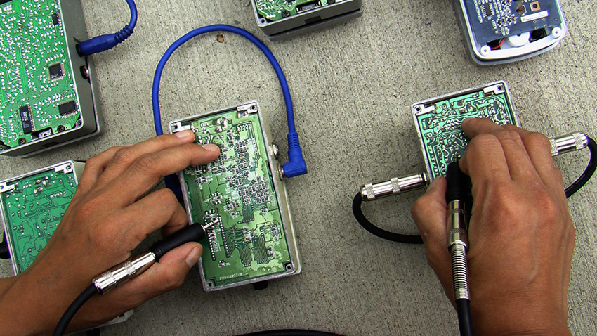
Figure 4 Bonnie Jones, digital delay pedal setup. Photo credit: Dani Restack.
Bonnie Jones's electronic setup offers her perspective on how one might explore the sonic affordances (if not personalities) of electronics. Jones's improvisations reveal sounds produced throughout the circuit board by removing the back cover, flipping the pedal bottom up, and touching a one-eighth-inch jack to various solder joints on the board. In contrast with Vic Rawlings's exploration of multiple types of pedal circuits (see his video in the “Laying of Hands: section of the Gallery on the website), Jones investigates generations of a specific series of digital delay effects. Each revision of the pedal has a different circuit layout, resulting in different feedback patterns that get piped to the P.A. This is not the way the manufacturer intended these pedals to be used, and each effect box reacts differently to the harsh feedback treatment, with some components misbehaving or failing over time. Jones's system thus almost hacks itself, much like the self-destructive cybernetic circuits of Louis and Bebe Barrons, which produced the soundtrack for the 1957 film Forbidden Planet and overheated themselves into malfunction.17 Jones states:
Electronic noise makes audible the hidden, the background, the "unwanted." It asks us to be inside of our bodies, to resonate with our surroundings. To be aware of each other, to listen. Our bodies vibrate with its secret messages, its rich complexity. The circuit board becomes a sonic geography, there are known localities, but also unknowable edges, everything is relation and context.18
For Jones, electronics serve an ethics of listening, realized in each performance and recording.
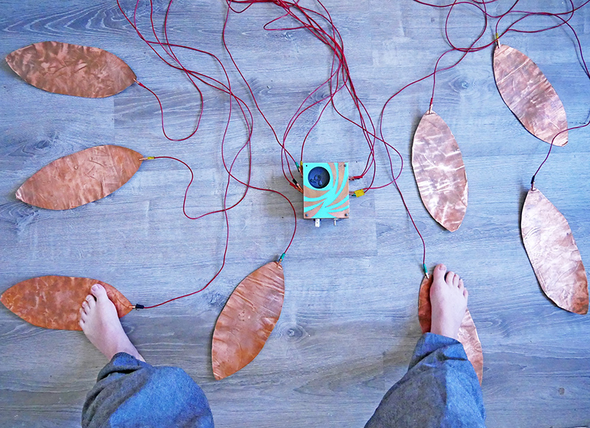
Figure 5 Anstasia Clarke, Cracklepads. Photo courtesy of the artist.
Adapting Michel Waisvisz’s classic 1970s Cracklebox circuit, Anastasia Clarke's Cracklepads (2018) take the historic, erratic circuit originally designed for finger control, and opens it to full-body interaction. Clarke's circuit differs from Waisvisz’s in a number of ways: it uses an NTE909D IC instead of the original 709, includes eight touch points instead of six (one placed on an empty pin of the 909D, and one on the output of the LM386), and adds a potentiometer after the 386, which unintentionally gave the device the capacity to self-oscillate. As such, it requires its user to touch the instrument to silence it.19 The interface is novel as well—Clarke drew inspiration from Peter Blasser's “androgynous nodes” to add brass nails in place of the Cracklebox's traditional touch points.20 She sees these as "neither input nor output, but cross-puts for making any number of unique connections."21 The design of her instrument includes elements that respond to this concern and affect modes of interaction. In performance, she wires these rods to large copper petals strewn around the performance space. The result is a full-body instrument that only functions when two or more nodes touch the skin.
Electromechanical
Artists such as Troy Rogers, Scott Barton or Steven Kemper have developed musical automatons—motors, microcontrollers and handmade instruments assembled in digitally-orchestrated ensembles that extend the long tradition of music boxes and player pianos.
Figure 6 Ragnhild May, The Flute Player (2015). Photo courtesy of the artist.
Ragnhild May's electro-mechanical systems, both installed and performed, explore the potential of recorders and air pumps as partially automated instruments. Reminiscent of Maryanne Amacher's psychoacoustic compositions, The Flute Player (2015) uses 132 fipple flutes, a vacuum cleaner and five air mattress pumps droning and chaotically generating otoacoustic phenomena. This offers a brute-force contrast with May's more recent, controlled installation system School Harmony (2018), which augments the flutes and air pumps with a microcontroller -automated system to direct the organ pump-bellows and valves to individual flutes of different sizes.
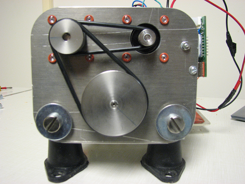
Figure 7 Jeff Snyder, Birl Tone Generator. Photo courtesy of the artist.
Jeff Snyder's Birl Tone Generators22 are stepper-motor driven dynamos whose power input is used as an output: as the motor's driveshafts get turned, they produce tones that are used as the basis of a subtractive synthesis system. Pulleys of smaller diameters are used for octaves, which are fed through waveshaper, filter and voltage-controlled amplifier. Thaddeus Cahill's Telharmonium performed additive synthesis and had a constant-speed central drive-shaft for every note and its octaves (see chapter 4), and the Birl Tone Generators are effectively comparable over a century later: electromagnets spinning to generate tones.23
From Scratch?
Although most of the projects described here could be considered to have been made "from scratch," some engage with the usually unchallenged substrate of circuits: the components and the printed-circuit-board themselves.
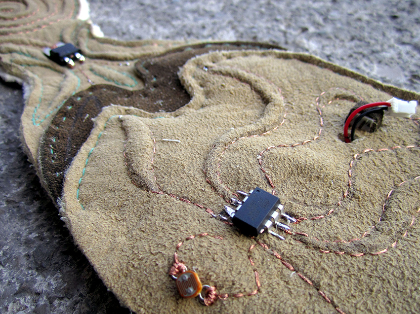
Figure 8 Hannah Perner-Wilson, Leatherphone. Photo courtesy of the artist.
With her Leathersynths (2013) Hannah Perner-Wilson investigates the possibility of developing electronic components locally rather than as part of a global market. Reflecting her working environment in Austria, the projects explore a variety of culturally and historically informed possibilities. Some employ a local relief embroidery technique (traditionally used to decorate lederhosen) to create conductive traces between components, as well an embroidered coil that functions as both electromagnet and membrane of a pair of Leatherphones. Other instruments are knitted with wool from local sheep that is combined with stainless steel fibers to make pressure and stretch sensors (see Chapter 16), or are woven using a Celtic card weaving technique to make multi-conductor ribbon cables with traditional patterns.
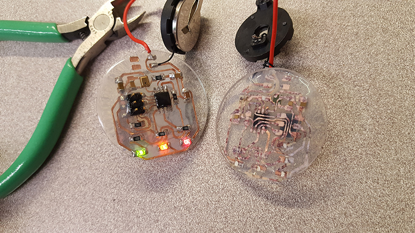
Figure 9 Victoria Shen, dB meter earrings. Photo courtesy of the artist.
Victoria Shen and her LED meter earrings extend material exploration in directions suggested by Perner-Wilson, Blasser (see Chapter 26) and Nyler Steiner (Jordan 2015, 44). Shen, who performs under the name Evicshen, worked in the mid-2000s helping Jessica Rylan build chaotic synthesizers as part of her Flower Electronics brand.24 Shen has built flexible vinyl-cut circuits that correlate the sound intensity picked up by a microphone to the brightness and color of LEDs. Presented as earrings, these wearable circuits offer visual feedback for and around Shen's sonic performances, indicating when sounds are reaching potentially dangerous levels of volume. Echoing the wearables and soft circuit work of Kat McDermott's Urban Armorseries, these handmade experiments offer an alternative basis for the assembly of circuits (clear vinyl) to complement a visual interpretation of sound.
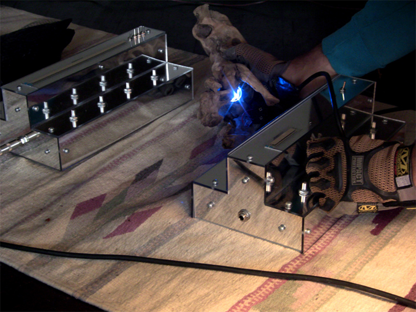
Figure 10 Two of MSHR's Nestar instruments, with control glove and LED light controller. Photo courtesy of MSHR.
MSHR (Brenna Murphy and Birch Cooper) have developed a number of custom audio-visual electronic instruments for immersive performance ceremonies and installations. The distinctive mirror casing of their devices is a functional decision. These instruments are often light-sensitive: the reflections from one enclosure onto another affect the sound. The Nestar is based on the quad NAND gate CD4093 IC. Each gate is wired as a square wave oscillator whose frequency control can be patched to MSHR's numerous light-sensitive controllers (photocells embedded in translucent plastics of various colors and shapes). A ribbon controller “bleeds” the IC’s power source, which extends the range of timbres and behaviors produced by the oscillators as they begin to operate erratically with low voltages. Performing with multiple Nestars, MSHR use a light organ to produce an array of beams aimed at the photosensitive controllers. They explicitly identify the sculptural aspect of their performance setup, focusing on the use of light filters to affect sound, as an opportunity to interact with signals in a unique controllable way that has shaped their output as musicians.
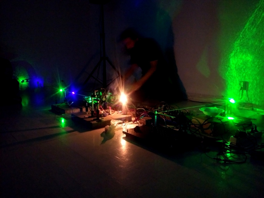
Figure 11 Martin Howse performs Final Session at Solu in Helsinki, 2019. Photo Credit: Solu Bioarts Society.
Echoing Gustav Metzger's auto-destructive art,25 and prompted by precedents as varied as the alchemical writings and illuminations of anonymous medieval scribes (detailed in the work of Deborah Harkness, Charlotte Fell Smith and Dame Frances Yates), Bram Stoker's Dracula, and the work of media theorist Friedrich Kittler, Martin Howse's performance setups and instruments involve heat and acids to transform materials. Citing Shintaro Miyazaki, Peter Flemming and Bengt Sjolen as contemporaries with similar interests, Howse engages with the composition of the components themselves, often using soil and other pulverized, molten or burnt mediums as electrical components, taking advantage of the fact that numerous familiar substances can conduct, resist or store electricity to some extent. His 2019 performance piece “Final Session”uses "earth, worms, burning matter, temperature sensors, violet laser and minerals" alongside custom electronic systems (for which he open-sources the code and circuit designs), to decode "earth and air signals through un-refined electrochemistry and manipulation of earth-bound electrons, air and light."26 For Howse these manipulations reveal the processes that lead to the existence of his tools, and in describing his interests he conveys the role of alchemy in shaping his approach to handmade electronic music:
That which is to be divined in the unfaithful language of replayed temperature change, earthy smoke, dust, glass machines, plant stones, and ear stones are the various past and future depositions, intrusions, compressions, degradations, and gradings of lithic entropy, these everyday deformations of contemporary energy.27
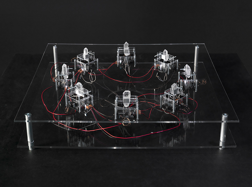
Figure 12 One of the five subsystems in Ralf Baecker's Irrational Computing. Photo credit: Roman März.
Ralf Baecker's Irrational Computing(2011) utilizes five interconnected modules based around crystals: silicon, germanium, galena and silicon carbide (all of which are used in microscopic amounts in integrated circuits) as the basis for grotesque, macroscopic mockeries of modern computing systems. Through photoelectric and piezoelectric effects, the crystals convert electricity, light and mechanical vibrations into other forms of energy. Some of these outputs are fed back into a complementary module, creating a complex feedback network. Echoing the concept of the circuit as score as well as the theme of musical chaos, media theorist Ryan Jordan describes Baecker’s pieces as having " no musical or compositional intention as such; instead, these works allow the machines, or rather the elements of the machines, to compose themselves." 28
Control
While some handmade electronic music has a tendency to engage with the more chaotic suggestions of the materials that surround us, a contrarian subcurrent has focused on the development of controllers for digital music synthesis systems. Working with the increasingly programmable nature of digital audio workstations and other software tools, and relatively ease to use standards, from MIDI to OSC, projects offering assignable knobs, switches and potentiometers have multiplied. A number of these are open source, encouraging the sharing of variations adapted by makers/composers/performers.29
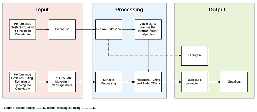
Figure 13 Functional diagram for Lia Mice's ChandeLIA instrument. Image courtesy of the artist.
Lia Mice's ChandeLIA (2018) is a chandelier augmented with a piezo microphone and an orientation sensor, wired to a Bela open source digital signal processing device (McPherson et al 2016), which adds low-latency audio inputs and outputs to a Beaglebone small Linux computer, as well as the ability to interface with various sensors. The signal from the piezo triggers a Karplus-Strong algorithm, connecting the chandelier to a digital, real-time model of a vibrating string that runs on the Bela-Beaglebone package.30 Various musical parameters of this algorithm are controlled, also in real time, by the orientation sensor in the chandelier. Musical behaviors are then achieved by moving, flipping, tapping and touching the chandelier.
Figure 14 Asha Tamirisa, Matrixharp. Photo courtesy of the artist.
Asha Tamirisa's Matrixharp (2015) is a hardware interface that utilizes a grid of stretch sensors and capacitive sensors to make patch connections and modulate parameters of digital synthesis. This interface and its corresponding software explore the potential of no-plug controllers, inspired by matrix interfaces of the ARP2500 and the EMS Putney. Matrixharp is motivated by a desire to move beyond the gendered and directional connectors of most electronic music hardware.31 In it, patch connections are “felt” throughout the system through the tension of the stretch sensors, resisting the localized logic of modular hardware. In accordance with the idea that all hardware hacking has political meaning (see Kori and Novak, this volume), the Matrixharp joins a growing set of handmade electronic music devices in which political explicitly influence design and, as a result, musical performance.
Figure 15 Quran Karriem and Rebecca Uliasz playing with the Synthball. Photo courtesy of the artists.
Quran Karriem and Rebecca Uliasz's Synthball developed as part of a wider intermedia project involving dancers, graphic artists and historical research directed by Thomas DeFrantz. It "includes three-dimensional accelerometer data, a gyroscope to measure changes in rotational orientation, [and] a magnetometer to measure gravitational fields."32 The streamed data controls a digital audio/visual synthesis system that can only be partially controlled: humans are not machine-like in their catching and throwing. The Synthball reminds electronic musicians that the motions such as throwing or bouncing a ball—so much more limited in precision than "knob twiddling"33 —have affordances worth exploring.34
There still is no conclusion35
There are as many visions of electronic music's future as there are instrument makers and designers. If no particular project from the last decade has emerged as the "next big thing" that Collins hypothesized in the second edition of Handmade Electronic Music (see “The Future Was Then” on the website), the categories and projects discussed above hint at shifts in nature of available materials and conceptual trends. From electro-musical chaos to technologically-mediated semblances of control, and across vibratory mediums, hacking remains a diverse and active mode of composition, responding to local cultural and political contexts. This is clear from my own partial perspective, but also many global case studies and longitudinal analyses (see in this book the essays by Curci et al., Van Gelder and Kelly, or Kori and Novak, as well as writing by Dal Farra, Flood, Gordon, Lerner).36 Given the role that handmade electronic music has come to play in the construction of communities, we can see how important it is to document both the making process and the conditions that enable it, as such documentation can foster further projects and extend awareness of shared values and of the systems of power inevitably at play.
Hardware is just where the hacking begins.
1 Collins, Nicolas. 2007. “Live Electronic Music.” In The Cambridge Companion To Electronic Music, 45. Cambridge: Cambridge University Press.
2 For a detailed theory of contemporary musical practices as inherently collaborative, see Georgina Born's relational model of musicology (Born 2010).
3 Lucier, Alvin. 1998. “Origins of a Form: Acoustical Exploration, Science and Incessancy.” Leonardo Music Journal, 5–11. We can expand the concept here to include all sorts of technical abstractions, from computer code to layout diagrams and interface designs, as they have since all been used to explicitly or implicitly prescribe and describe musical works to various extents.
4 See Collins 2009. Handmade Electronic Music: The Art of Hardware Hacking. Second. New York and London: Routledge, p 297.
5The current fuzz pedal market is a good example.
6 Rodgers, Tara. 2015. “Cultivating Activist Lives in Sound.” Leonardo Music Journal 25: 79–83.
7 The philosopher of technology Gilbert Simondon would call that process individuation Simondon, Gilbert. 1958. Du Mode d’existence Des Objets Techniques. Paris: Aubier.
8 There are too many examples to list but see, for example, Holzer, Derek. 2010a. “Schematic as Score: Uses and Abuses of the (in) Deterministic Possibilities of Sound Technology.” In Vague Terrain 19, edited by Derek Holzer.https://web.archive.org/web/20131124040627/http://vagueterrain.net/journal19, the circuit tracing subforums on freestompboxes.org, or the growing field of media archaeology: Parikka, Jussi. 2011. “Operative Media Archaeology: Wolfgang Ernst’s Materialist Media Diagrammatics.” Theory, Culture & Society 28 (5): 52–74; Striegl, Libi, and Lori Emerson. 2019. “Anarchive as Technique in the Media Archaeology Lab Building a One Laptop Per Child Mesh Network.” International Journal of Digital Humanities, April.https://doi.org/10.1007/s42803-019-00005-9.
9 Non-hierarchical electronic instrument taxonomies offer the advantage that they can be expanded to match the self-labeling of these disparate practitioners and ad-hoc communities. See Magnusson, Thor. 2017. “Musical Organics: A Heterarchical Approach to Digital Organology.” Journal of New Music Research 46 (3): 286–303.
10 In physics, "jerk" is the third derivative of displacement with respect to time, which can also be thought of as the time-derivative of acceleration (Sprott, Julien Clinton. 2011. “A New Chaotic Jerk Circuit.” IEEE Transactions on Circuits and Systems II: Express Briefs 58 (4): 240–243). Incidentally, Sprott co-authored paper on these type of chaotic oscillator circuits with Jessica Rylan-Piper, mentioned below: Piper, Jessica Rylan, and Julien Clinton Sprott. 2010. “Simple Autonomous Chaotic Circuits.” Circuits and Systems II: Express Briefs, IEEE Transactions On 57 (9): 730–34.
11 See Dunn, David. 2011. “Thresholds and Fragile States.” Unpublished Score.
12 Cuervo, Adriana P. 2011. “Preserving the Electroacoustic Music Legacy: A Case Study of the Sal-Mar Construction at the University of Illinois.” Notes, 33–47. Franco, Sergio. 1974. “Hardware Design of a Real-Time Musical System.” Urbana-Champaign: University of Illinois. PhD Thesis.
13 Nakai, You. 2016. “On the Instrumental Natures of David Tudor’s Music.” New York University. PhD Thesis.
14 Kant, David. 2017. “Thresholds and Fragile States by David Dunn.”http://www.davidkant.com/thresholds/index.html.
15 Kant, David, and Madison Heying. 2018. “Blonda.” February 23, 2018.
16 White, Philip. 2018a. “Feedback Instrument (Pt 1).”http://prwhite.net/instrument-pt1/.
———. 2018b. “Feedback Instrument (Pt 2).”http://prwhite.net/feedback-instrument-pt-2/. Gillet, Emilie. 2019. “Veils.”https://mutable-instruments.net/modules/veils/open_source/.
17 Greenwald, Ted. 1986. “The Self-Destructing Modules Behind Revolutionary 1956 Soundtrack of Forbidden Planet.” Keyboard Magazine, February 1986.
18 email exchange with the author, Nov. 8, 2018.
19Clarke, Anastasia. 2018. “Self/Work: Performing Attention in an Exploration System.” Master's Thesis, Mills College, 53.
20 Blasser, Peter. 2015. “Stores at the Mall.” Wesleyan University. Master's Thesis, 32, 67
21 Clarke 2018, 53
22 Snyder, Jeff. “Birl Tone Generator - Close Up of Prototype.” https://vimeo.com/15472241; “Research.” 2010.http://www.scattershot.org/research.htm.
23 Cahill, Thaddeus. 1897. Art of and apparatus for generating and distributing music electrically. US Patents Office.
24 Rylan had herself worked with synth designer Donald Buchla prior to starting Flower Electronics.
25 Metzger, Gustav. 1969. “Automata in History.” Studio International. Wilson, Andrew. 2008. “Gustav Metzger’s Auto‐Destructive/Auto‐Creative Art: An Art of Manifesto, 1959–1969.” Third Text 22 (2): 177–94.https://doi.org/10.1080/09528820802012844.
26 Howse, Martin. 2019. “The Final Session.”http://www.1010.co.uk/org/final.html.
27 Ibid
28Jordan, Ryan. 2015. “DIY Electronics: Revealing the Material Systems of Computation.” Leonardo Music Journal 25 (25): 44.
29 See for example Chang, Kevin. 2019. “Pd Knobs.” Sonoclast: Electronic Instruments for Music. http://sonoclast.com/products/pd-knobs/; or the 16n in Crabtree, Brian, Sean Hellfritsch, Tom Armitage, and Brendon Cassidy. 2017. “16n.” https://16n-faderbank.github.io/.
30 Sullivan, Charles R. 1990. “Extending the Karplus-Strong Algorithm to Synthesize Electric Guitar Timbres with Distortion and Feedback.” Computer Music Journal 14 (3): 26–37.
31 Blasser 2015, 1
32 Karriem, Quran and Rebecca Uliasz. 2017. “Synthball.”http://qurankarriem.com/portfolio/synthball/.
33 Paradinas, Mike and Richard D. James. Expert Knob Twiddlers. Rephlex, 1996. Record released under the name "Mike and Rich".
34 Evens, Aden. 2005. Sound Ideas: Music, Machines, and Experience. University of Minnesota Press:160, Rovan, Joseph “Butch.” 2009. “Living on the Edge: Alternate Controllers and the Obstinate Interface.” Mapping Landscapes for Performance as Research: Scholarly Acts and Creative Cartographies.
35 Collins 2009: 294
36 Dal Farra, Ricardo. 2006. “Something Lost, Something Hidden, Something Found: Electroacoustic Music by Latin American Composers.” Organised Sound 11 (2): 131–142; Flood, Lauren. 2016. “Building and Becoming: DIY Music Technology in New York and Berlin.” Columbia University. PhD Thesis; Gordon, Theodore Barker. 2018. “Bay Area Experimentalism: Music and Technology in the Long 1960s.” University of Chicago; Lerner, Martín Matus. 2019. “Latin American NIMEs: Electronic Musical Instruments and Experimental Sound Devices in the Twentieth Century.” In Proceedings of the International Conference on New Interfaces for Musical Expression.
A History of Japanese Hacking and DIY music
ADACHI Tomomi
Translation by Sayoko Mundy
ADACHI Tomomi
Translation by Sayoko Mundy
Is it unreasonable to start a history of Japanese hacking and DIY music with the year 1924?
That was the year TAKAMIZAWA Michinao, perhaps inspired by Luigi Russolo’s Intonarumori instruments, took some bicycle wheels, metal strings and empty cans and combined them to create his Sound Constructors. (The creator of Japan's first robot manga, Takamizawa later became a famous cartoonist under the name TAGAWA Suiho ). The documentation is sketchy, but it is clear that these devices were used by the Japanese Dada group MAVO in dance and theatre performances where they were played by people with no musical background. They might be the first Noise Improvisations in the history of modern art. Three decades later in 1956, TANAKA Atsuko, a core member of the avant-garde group Gutai, created her Electric Dress—a mass of light bulbs and wires that she wore fully lit, despite the risk of electrocution, on stage. A year earlier she exhibited a work in which twenty bells could be rung in sequence when visitors pressed a button, a very early example of an interactive sound installation.
As in the United States and Europe, in Japan the 1960s were critical years for art as well as politics. Among the members of the Group Ongaku, founded in 1960, were two important pioneers of electronic experimental music, TONE Yasunao and KOSUGI Takehisa (1938–2018). Tone created one of the first artworks using a tape loop for the “Yomiuri Independent exhibition,” a critical occasion for avant-garde art, in 1962, and in 1965 transformed the body of a Volkswagen into an interactive sound object. This interest in the transformation of content through changes in media—audio tape to visual object, automobile to musical instrument—would remain consistent through Tone’s career. Kosugi, who was familiar with electronics from repairing radios in his youth, created ethereal electronic sounds by heterodyning closely tuned radios (see David First’s audio and video tracks on the website). He built his own Theremin and altered his live violin performance through filters and delay pedals to gently transform sound and space.
A unique attribute of Tokyo, essential to the development of Japanese electronic music, was the Akihabara district—the urban temple of electronics. After World War II, Akihabara was the epicenter of the black market in the destroyed city center, and later small shops selling military surplus vacuum tubes and radio parts crowded the area around a local school for electronics. The narrow arcade was so jammed with vendors it was difficult to pass, but how exciting to survey the precisely organized arrays of parts and junk, and chat with the sometimes-difficult shop owners. Akihabara nourished Japanese DIY culture: you could find new or old things at incredible prices, and every Akihabara regular would have had a map of it imprinted in their brain. It offered a mysterious flow of imagination not to be had through catalogs or mail order. You might go to buy things, but you would leave with ideas—a modest collusion of capitalism and creativity. By the 1990s Akihabara had devolved into a purlieu of anime and video-games, but one can still catch a glimpse of older times in a bin of electric parts labeled “new old stock” not found on the Internet. Some have been there for decades.
Several engineers had significant roles in the 1960s development of electronic music in Japan. OKUYAMA Junosuke began as a recording engineer collaborating closely with composer TAKEMITSU Toru (their film work is a précis of the best Japanese film of the sixties) and went on to support and influence many experimental musicians, including international visitors to Japan. He met John Cage and David Tudor in 1962 when they were invited by the Sogetsu Art Centre, then the heart of the Tokyo contemporary art scene (though it strains credibility, Sogetsu was sponsored by the Ikebana flower arranging school Sogetsu-ryu). Okuyama was the resident sound engineer, and his relationship to Cage was cemented when he built in one night a 50-channel mixer for Cage’s 50 contact microphones (the microphones had been made in Japan but, curiously, brought by Cage from America). Perhaps more importantly, for the subsequent history of electronic music, Okuyama, who could not speak English, took Tudor, who did not understand Japanese, to Akihabara. Cage wanted to bring Okuyama back to the US, but this did not happen. Instead Cage took home technology and the spirit of Zen, a form of Orientalism Western intellectuals like; while Tudor brought back a fascination with live electronics that blossomed instantly. Okuyama continued to assist musicians by building multipliers, filters, ring modulators and other devices. Cage’s pupil ICHIYANAGI Toshi used these tools in performing his own compositions, and at times Okuyama himself got up on stage. While the nation’s most important electronic music studio, NHK Electronic Music Studio (under the aegis of Japan’s national broadcasting corporation, NHK,) was mainly interested in tape music, Okuyama’s work greatly expanded the field of live electronics.
It was in Akihabara in 1963 that the engineer ABE Shuya met artist Nam June Paik, who had studied in Japan and was a frequent visitor. Together they built Robot K-456 (1964), who performed in the groundbreaking street performances. Later Abe designed the Paik-Abe video synthesizer, based on specifications from Paik, as part of a project with WGBH television in Boston.
The tradition of art-oriented engineering in Japan can be traced back to the legendary UCHIDA Hideo (one story has it that he was the actual inventor of the transistor.) In 1962, having previously worked at the NHK research laboratory, he opened a shop in Akihabara (the store remained in the same place with the same name until quite recently). Later he devoted himself to elucidating paranormal phenomena through electrical engineering. Echoes of Uchida can be heard in the work of artists SHII Kei and MURAI Keitetsu . In the 1970s Shii had studied with Kosugi at Bigakko, the base for anti-academic education at the time. He has since provided electronic devices for many artists, and with other Kosugi alumni is a member of Marginal Consort, which employs a wide range of electronic instruments. MURAI Keitetsu assisted Kosugi with electronics in later years, and is known for solo performances, most memorably those using a candle flame to trigger an array of oscillators to produce a resounding roar.
YOSHIDA Minoru, a member of the Gutai group, developed his work using technologies in a psychedelic way, and in 1974 built synthesizer components into a plastic jacket. Wearing this synthesizer jacket, Yoshida suspended himself with ropes and performed mid-air—linking wearable electronics and Sun Ra.
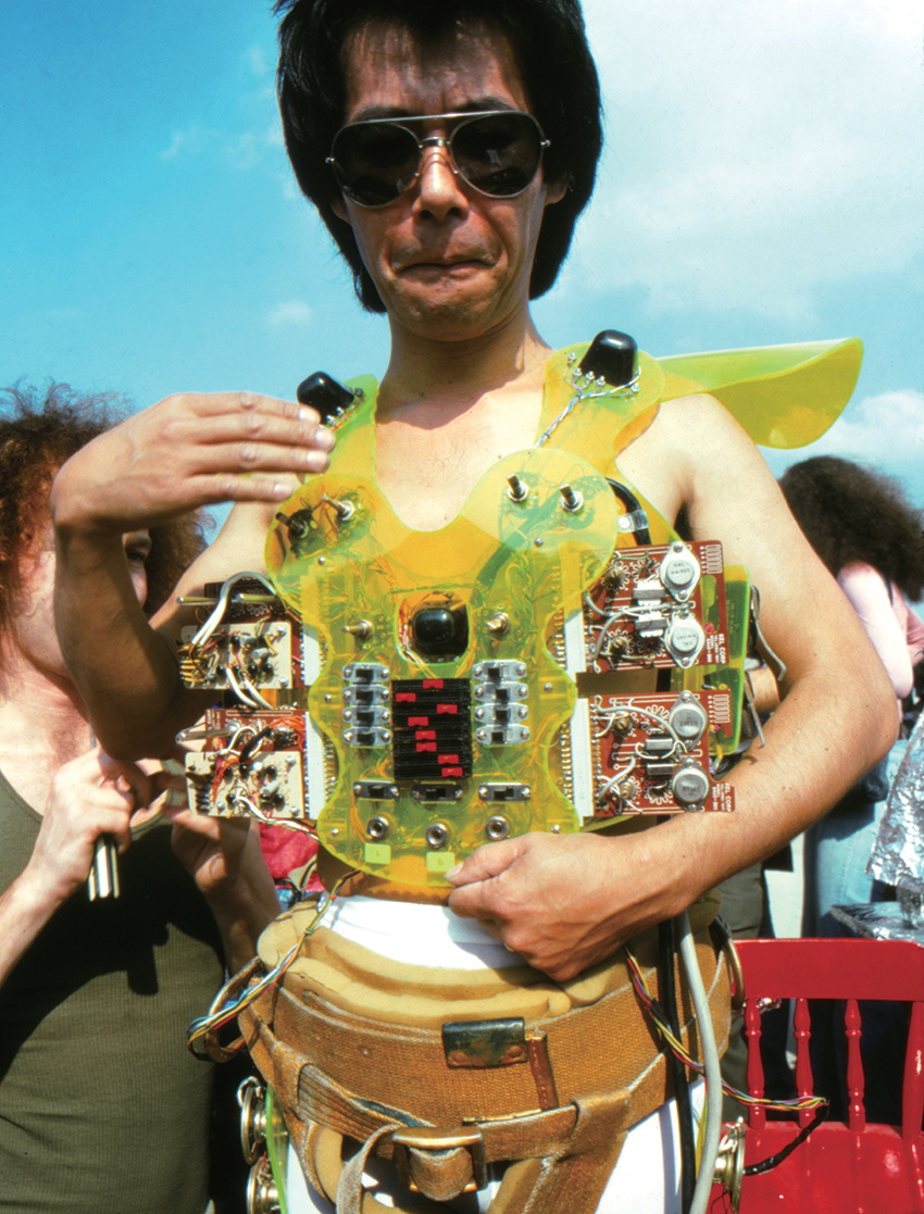
Figure 1 Synthesizer jacket, YOSHIDA Minoru. Photographer Unknown courtesy of Midori Yoshida and Ulterior Gallery, New York, used by permission.
I would like to take this moment to correct a misperception about Japanese culture common among Western readers—namely the idea that Japan has nurtured its own consistent and continuous culture, independent of the United States, Europe and other places. As already observed, there was Dadaism in Japan in the 1920s, and the Japanese avant-garde of the 1960s was perfectly synchronized with that of New York City. There was always influence from the West, but there is no need to lament “cultural imperialism. ”Dadaism may have reached Japan from Berlin, but it was accepted in Japan only because similar things had already taken shape there. Similarly, the musical work of Group Ongaku commenced without direct knowledge of Cage or of Fluxus, but when their ideas were imported, they resonated with the Japanese avant-garde. In other words, Japan shared in the Zeitgeist of the 20th century.
That said, one possible, and unfortunate, peculiarity of Japanese culture is a dearth of communication between different generations and different regions in Japan. Thus there was little relationship between 1920s Dadaism and the 1960s avant-garde in Japan—somehow the distance was much greater than the (mathematically equivalent) one between Duchamp and Fluxus. The physical distance between Tokyo and Osaka, the two cultural poles in Japan, is only 400 km, but the cultural gap seems greater than that separating New York and San Francisco. The meeting point for Group Ongaku (Tokyo) and Gutai (around Osaka) ran through John Cage’s loft in New York City.
In the 1970s and early 1980s, a new DIY culture, punk, exploded in Tokyo. For better or worse, there was no Japanese equivalent to Malcolm McLaren, and the punk scene remained an underground phenomenon. IMAI Jiro, who was involved in the strangest band, Pungo and the most self-destructive band, Taco (“octopus”), expressed the DIY spirit with honesty and humor. Around 1990 he started Jirox Dolls Show as a solo effort, using dolls and rubbish combined on stage with light bulbs, cheap turntables, electric fans and other household appliances. A performance using an electric mixer to turn a disc placed above a hat conveyed a meaningless purity. Imai died in 2012, but during his final days in hospital, he photographed objects created from hospital food, images that still speak to us about what is hacking, what is DIY, what is art, truth and love. In Osaka also the punk scene boomed, characterized by the use of effects and unusual explosive sounds that later became common to Japanese noise music1.

Figure 2 Turnhat, IMAI Jiro, and food art. Photo © IMAI Jiro, used by permission.

Figure 3 Food art, IMAI Jiro. Photo © IMAI Jiro, used by permission.
Guitarist TAKAYANAGI Masayuki was a pioneer of the free jazz movement in Japan, from which he drew his methodology of “action direct” in the 1980s. Takayanagi placed a number of electric guitars on a desk; these were activated by motors and heard through a ring modulator and numerous effect pedals, accompanied by tape material and feedback, The result was an incredible, roaring sound performance. Takayanagi’s disciple IMAI Kazuo (like Shii, a former student of Kosugi’s), attached springs to a metal plate and performed with it as part of the Marginal Consort and in solo performances. OTOMO Yoshihide, another student of Takayanagi, created a number of “action direct” mechanisms, and had played twisted noise on an electric guitar to which he had added springs.
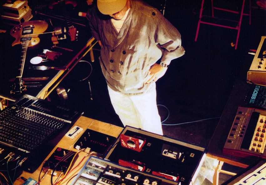
Figure 4 Action Direct, TAKAYANAGI Masayuki. Photo © SAITO Yasunori, used by permission.
Figure 5 Table set-up for Marginal Consort, IMAI Kazuo,. Photo © FUNAKI Kazuyuki, used by permission.
Composer and pianist TAKAHASHI Yuji has had a large influence as a role model for anti-academic composers and performers in Japan. A student of Iannis Xenakis, Takahashi commissioned and premiered Xenakis’s solo piano piece “Herma” (1961). Though it would be impossible to do justice to his extensive activity in hacking and electronics here, it is important to acknowledge his computer improvisations of the late 1980s and early 1990. Working with Mac and a sampler, he often collaborated with the legendary improviser TOGASHI Masahiko , as well as with the American composer John Zorn, who lived in Tokyo at the time. He used the programming language Max, in which the user connects digital “objects” (discrete processing elements) with lines, mimicking the physical process of connecting components with patch cords: on stage Takahashi would sometimes work with his back to the audience so they could watch the screen as he added or deleted Max objects, clicking and dragging patching cables to connect or disconnect them. These performances could be described as “live coding,” but they might as accurately be dubbed “live cording.”
Bassist YOSHIZAWA Motoharu, like Takaynagai and Togashi, started in free jazz, where he became a leading figure. Always in the forefront of improvised music, he developed in the late 1980s a system in which a homemade vertical electric bass was connected to a DJ sampler and other effects, modified so that they could be delicately controlled with his feet as he played the bass. This enabled him to perform real time sampling and modulation, creating an orchestra-like accompaniment from vertically placed speakers, resulting in very lively improvised electronic music.
In the new millennium, the Internet has linked communities around the globe and facilitated our access to information, in Japan as elsewhere. I would like to mention seven artists among the many who have emerged in this milieu.
ITO Atsushiro had long included fluorescent lights in his installations, but around 2000 he began amplifying the sound of the lights with electromagnetic pickups in audio visual performances. He dubbed this instrument the Optron, and used it in collaborative efforts with other improvising musicians. In 2003 he reduced the system to a single fluorescent tube, held like a guitar. His performance style mimics rock guitar— the most sophisticated style of musical performance to be developed in the last 50 years. The guitar is abandoned. And the strobe is your own!
Figure 6 ITO Atsuhiro, Optron. Photo © FUJISHIMA Ryo, used by permission.
Along with Ito, SUZUKI Manabu is a member of IMAI Kazuo trio mentioned above (in this group Imai acts exclusively as an outstanding jazz guitarist). In addition to building electric instruments for other artists, Suzuki performs his own work with a large number of eccentric electric devices, that translate chemical and physical motion data into sound. One performance work amplifies the electric potentials of an electrolysis of water; in he holds both his hands in a horizontal position for around 20 minutes; as the hands start to shake, sensors catch the movements and transform them to sounds.
YONEMOTO Minoru has invented a large number of unconventional electric devices that explore the territory between conceptual art and fetishism. In performance, he manually sends 8-bit commands to an early digital music chip using a combination of switches and buttons, collapsing the distance between the human body and digital technology. With more than 150 modules, his System Y appears to be a normal self-made synth, but it contains a compass, an accessories case and a spring-powered walking toy. Until Handmade Electronic Music was translated into Japanese in 2013, Yonemoto’s book Fun Electronic Musical Instruments: An Introduction to DIY (2008) was the only guide for experimental musicians written in Japanese2.
Figure 7 System Y, YONEMOTO Minoru. Photo © YONEMOTO Minoru, used by permission.
One of the most prominent contemporary artists in Japan at the moment is MOHRI Yuko. Many of her kinetic installation works employ chains of devices and objects activated by solenoids and motors. Her projects combine a refined minimalist aesthetic and the unpretentious joy of self-made objects. KUBOTA Akihiro teaches media art at Tama Art University. Active on the “live coding” scene, he also performs on an electric guitar into which he has incorporated a breadboard for prototyping circuitry, an Arduino, contact microphones, optical sensors and a video synthesizer.
Figure 8 Breadboard Guitar, KUBOTA Akihiro. Photo © KUBOTA Akihiro, used by permission.
TAKESHITA Yuma is a member of the emerging younger generation. He has attached numerous sensors and mechanisms— including one that can rotate a knob automatically—to an electric bass, allowing him to control effect devices and synthesizers in improvisations. He frequently collaborates with NAKADA Kayu who, unlike many of those involved in the Japanese independent music scene, has trained in traditional composition methods at the Senzoku Gakuen College of Music. Nakada regards circuit bending as an extension of the concept of the prepared piano (adding wires to an open can be seen as analogous to placing objects in the strings of the piano). Nakada extracts components from electric keyboards and stacks them in large numbers to make electrical contact, creating unexpected sounds. These performances are representative of the best aspects of the Japanese hacking music scene in Japan today.
Figure 9 Electro-bass, TAKESHITA Yuma. Photo © TAKESHITA Yuma, used by permission.
Figure 10a NAKADA Kayu, Bug Synth. Photos © NAKADA Kayu, used by permission.
Figure 10b NAKADA Kayu, Bug Synth. Photos © NAKADA Kayu, used by permission.
1See David Novak, 2013, Japanoise: Music at the Edge of Circulation, Duke University Press.
2Minoru Yonemoto, Tanoshii denshi gakki: jisaku no susume [楽しい電子楽器 自作のススメ] (Tokyo: Ohm, 2008).
Thanks to KIM Yohan
日本のハッキング・DIY音楽史 (足立智美
Original Japanese version of A History of Japanese Hacking and DIY Music (ADACHI Tomomi)
A History of Japanese Hacking and DIY Music (without images) A History of Japanese Hacking and DIY Music (with images)
Livening Things Up: Australian Hand-Built Electronic Instruments
Caleb Kelly and Pia van Gelder
Australia is in many ways an outpost for sound practices and experimental music. Works that originate here often look outward to relatively nearby areas such as South East Asia, the South Pacific and East Asia, as well as to the canonical practices of Western experimentalism. But Australians also look inward to their own history of sound art. Larrikin, a common local term for someone who does not observe convention, is likely derived from the verb “lark”—to play or behave in a mischievous way, and many of the artists discussed in this essay demonstrate larrikin behavior. Their style of making welcomes the public with a reflexive, self-deprecating sense of humor. They tinker with found materials and hack toys, microwave ovens, automobiles, bandsaws, breadboards, e-waste and volatile gases. Some are more serious about it than others.
There are three dominant approaches to hand-making electronic sounds in Australia: appropriating everyday electronics through hardware hacking; positioning human bodies as a kind of hardware that can control, or be controlled by, electronics; and investigating cosmic energies of the electromagnetic spectrum. This chapter does not pretend to present a complete list of attitudes or of instruments, only to offer a gathering some examples of how recent artists have developed the ideas and processes of handmade electronic music in Australia.1
It is important first to acknowledge, however, earlier Australian instrument makers who established ways of working with handmade electronics. In the 1970s Joseph Stanislaus Ostoja-Kotkowski (1922–1994) and dancer Philippa Cullen (1950–1975) used the electromagnetic spectrum in their sculptural theremins and experimented with biofeedback.2 Other artists active in this early period include Warren Burt, Ron Nagorcka, David Chesworth, Tsk Tsk Tsk and those who worked at the Clifton Hill Community Music Centre in Melbourne, as well as the Bush Video collective in Sydney.
On an episode of the 1986 Australian TV music show Edge of the Wedge about the electronic post-punk band Severed Heads, the presenter’s head speaks from a cathode ray tube set atop a rack of electronic gear, and remarks: “it’s getting a bit boring in here, can you do something to liven it up?” Band member Stephen Jones obliges by tweaking knobs on his home-made video synthesizer, whose nest of wires and circuit boards is visible beneath the acrylic plastic cover. The presenter’s face is then surrounded by colorful geometries and pulsing, waveforms.3
More recently, handmade synthesizers and hardware hacking continued to motivate by communities such as the record label Clan Analogue (1992–), the Sydney chapter of Dorkbot (2005–), and the Instrument Builders Project (2013–), along with many spaces and collectives, including Lanfranchis (2002-2007) and Serial Space (2007-2013) in Sydney, the Wired Lab in Wagga Wagga (2007–), and Electrofringe Festival (1998–).
Playing with the Everyday
Since 1995, the band Toy Death have been performing on stage in endearingly elaborate, somewhat terrifying toy-like costumes, attempting to play metal music with an array of circuit-bent toys that would impress any child by its sheer number. The interesting contradictions of this task can be heard in their most popular song, “Barby Army” (2012). In concert, they build dance-worthy tunes from layers of sound, emphatically pushing the buttons of toys, quickly scrambling and distorting the farm house noises and buoyant built-in jingles, turning voices from cheerful to scary, converting bovine moos to the groans of some unidentifiable creature. Cathartic endings to their songs are produced when the grown-up toy-people collapse structure and discipline.
Figure 1 Toydeath performing at OP SHOP: TOYDEATH in 2013 at Maitland Regional Art Gallery.
Photo © Luke McMaster, used by permission.
In Brisbane, Ross Manning and Alan Nguyen formed Faber Castell (2003-2008) with a collection of dodgy instruments. They created rhythms with “records” made of sandpaper and lenticular prints, drums with contact mics connected to effects pedals, and a Synare (an early percussion synthesizer in drum-like form). Volatile feedback erupted from speakers fed from headphones acting as microphones, wrapped around the drums, while Nguyen and Manning attempted to communicate with the audience by laying hands on circuit-bent Walkie-talkies. By shining light through acetate prints on a spinning fan, they modulated photoresistors at rapid speed. Their sets would often end destructively, with the performers playing drums with their heads, sticking pins in Walkmans or pouring beer on the electronic equipment, permanently damaging its sonic character.4 They would then un-clean up the dance floor with an inverted vacuum cleaner, that blew air into a rubber glove fitted with party horns for fingers; shifting the settings of the vacuum would modulate the pitch of the squealing horns.
Figure 2 Faber Castell, Liquid Architecture festival in Melbourne 2004. Photo © Alan Nguyen, used by permission.
Hirofumi Uchino of the noise band Defektro (1995-) plays home-made instruments carefully crafted from collected metal parts. Uchino often appears with guitar-shaped assemblages such as the QSG2-1 (2006), in which a large amplified spring takes the place of strings, and is vibrated by a rotating disk. Other instruments take less familiar forms: the HBS (1996) looks like a curling wand, repurposed to create harsh metallic sounds. The Discharger (1998)—a portable remake of David Tudor’s Fluorescent Sound (1964)—consists of a small fluorescent lamp mounted on a compact electronic box in the style of early tube amplifiers. The electromagnetic frequencies generated by the gas-discharge tube and its supporting electronic parts are amplified and modulated by a built-in equalizer. Uchino’s Electric Maraca (1997) resembles an incandescent light bulb, its plastic spherical casing enclosing springs that suggest filaments but are actually pickups played by small phosphorescent pieces of plastic that bump around the enclosure when shaken.5
Figure 3 Hirofumi Uchino’s DC - Discharger (1998) with the light on. Photo © Hirofumi Uchi, used by permission.
Figure 4 Hirofumi Uchino performing with his QSG-defektro 3 (2011) at the International Noise Conference at Dirty Shirlow’s, Sydney Australia. Photograph by Veronica Evans, used by permission of Hirofumi Uchi.
Playing with Bodies
Co-author Pia van Gelder’s performance work PVG sans PCB (2014–) is not so much an instrument as a potential instrument. The performance begins with a table, a divided box of electronic components, an empty breadboard or two, and a mixing desk. Van Gelder starts by building a CMOS Hex Schmitt Trigger oscillator from scratch (see chapter 13). Sounds emerge as she adds components (capacitors, pots, diodes), gradually becoming denser and more interactive. For example, a photoresistor may be inserted, followed by a strobing LED to “rhythmatize” the synthesized sounds. She also combines conductive objects—a piece of fruit, a cream bun—as variable resistors that can be squeezed and mushed. Often her fingers are integrated into the networks, the conductivity of skin completing electrical connections. A butcher’s glove made of steel mesh acts as a complex switch when oscillators are connected. The provisional nature of the breadboarded circuit facilitates experimentation, and the instrument is dismantled and returned to the tackle box at the end of each performance.
Figure 5 Pia van Gelder performing PVG sans PCB at Liquid Architecture: Rare Earth, Heavy Metal, Westspace, Melbourne 2015. Video still, Alex Cuffe, © Pia van Gelder, used by permission.
Sydney-based musician and composer Donna Hewitt developed a microphone stand, known as the eMic, in 2003 with the help of Ian Stevenson. The performer’s gestures are mapped by transducers, and various sensors built into the microphone and stand. This data is then manipulated via digital processing in performance.6 Similarly, drummer Alon Ilsar’s AirSticks (2007) take air drumming to a new level by exploiting the gestures of drumming and gaming. The instrument is built from off-the-shelf gaming controllers that are patched into a computer to allow Ilsar to trigger sounds and visuals. Artist Michaela Davies inverts these approaches to gesture and circuitry by circuit bending the body using electric muscle stimulation (EMS). In her best known work, Cyborg String Quartet (2013), the performers are connected to a custom-built EMS machine that choreographs their actions through direct, sometimes painful, muscle stimulation. They attempt to play their instruments while convulsing, producing spasmodic tunes with “prepared arms” rather than “prepared violins.”
Figure 6 Alon Ilsar playing his AirSticks (2007) at Trigger Happy 'Visualised', 2018, the Old Darlington School, Sydney. Photograph by John Dennis, © Alon Ilsar, used by permission.
Figure 7 Donna Hewitt performing with her eMic (2003) at Vivid Music Festival, 107 Projects, Sydney 2017. Photograph by Rhiannon Hopley, © Donna Hewitt, used by permission.
Figure 8 Michaela Davies performing with her Involuntary String Quartet at Musicircus, John Cage Centenary Celebration at the Sydney Opera House in 2012. Photo © Michaela Davies, used by permission.
Since 2005 dorkbot Sydney has sponsored presentations and experiments in electronic instrument building with artists such as Dan Stocks (aka Diode Dan) in artist-run spaces such as Lanfranchis7. Stocks’s Radar Synthesiser (2009) uses a salvaged Gunn diode to generate 24Ghz microwaves that can track moving objects or dancing bodies, detecting range and velocity. In dorkbot workshope groups of people gathered to build instruments together. Artist/engineer Aras Vaichas’s Micropatch Synth (2011), a microprocessor-based, cheap and nasty simulation of a modular synth, provided opportunities for learning about electronics while making instruments. Samuel Bruce’s Ritual Solar Observance Society (2012) created an orchestra from hacked solar garden lamps, with new sound-making components neatly arranged inside the original housing. Bruce conducted performances at sundown to celebrate the turning of celestial bodies; as the sun set, the instruments dwindled and died, until reactivated by light at dawn.
Figure 9 The inside of Danial Stocks’ Radar Synthesizer (2009). Photo © Danial Stocks, used by permission.
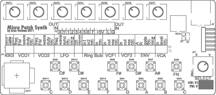
Figure 10 Front panel silkscreen of Aras Vaichas’s Micropatch Synth (2011). Photo © Aras Vaichas, used by permission.
Figure 11 Sam Bruce and participants performing RSOS at Cementa, 2015, Kandos, NSW. Photograph by Kate Byrne, © Sam Bruce, used by permission.
Playing with Earth Energies
Media artist Joyce Hinterding, who lives in the Blue Mountains of New South Wales, has been working with electromagentic waves across the radio spectrum since the 1990s. A reoccurring element in her installations is the antenna, sometimes taking on the familiar shape of TV aerials, as in Purple Rain (2004) (with David Haines), but at other times taking unexpected forms, as in her drawings with carbon smudged and smeared with audience interaction. In 2009–2010 Hinterding produced a series of works entitled Aura in which images, generated algorithmically and drawn with liquid graphite, act as antennae; they pick up VLF (very low frequency) signals from the atmosphere, and also provide a grounding effect, similar to putting your thumb on the end of a guitar jack. The closed circuit creates a hum, and by moving fingers across the drawing, viewers raise and lower the amplitude of the hum. Through carbon-based media and transduction, Hinterding makes audible the energies that surround and bombard the space in which her works reside.
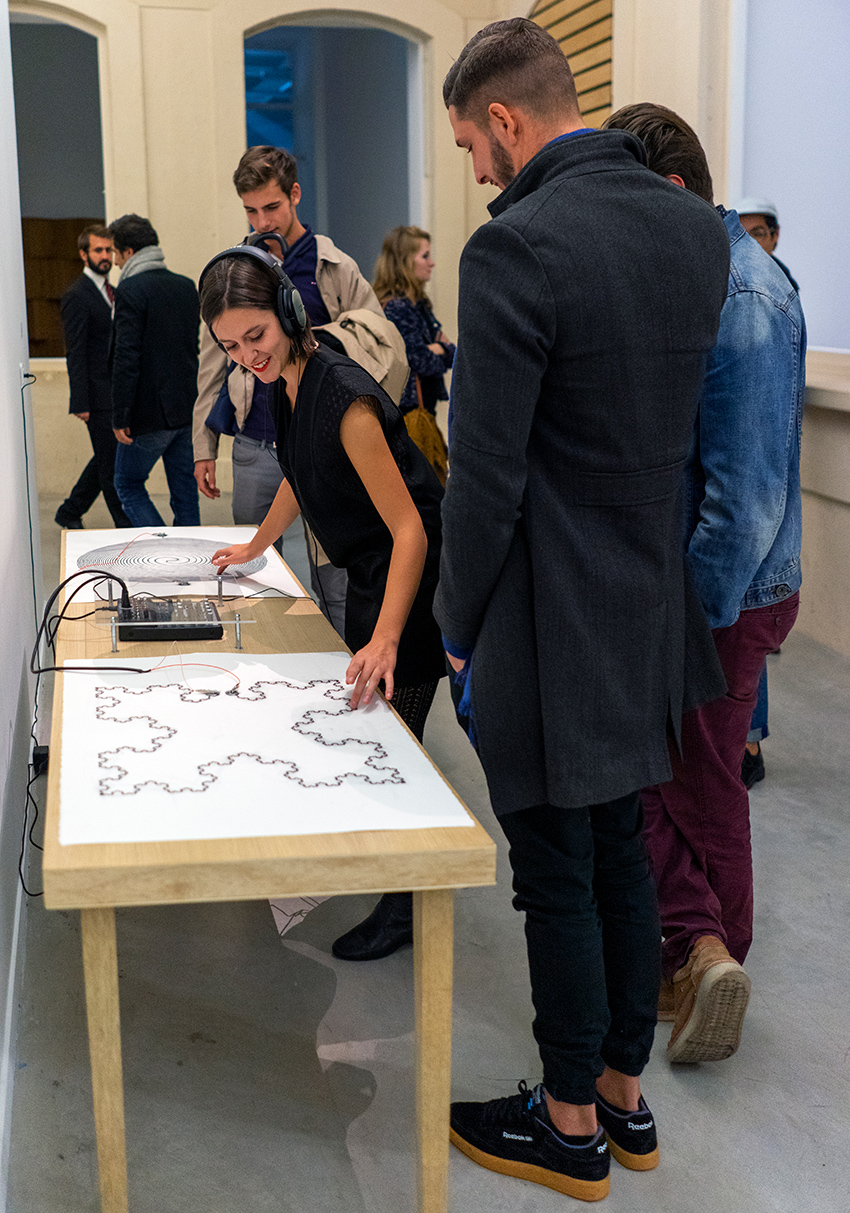
Figure 12 Installation view of Joyce Hinterding’s Aura (2009 -2016) at La Panacée Montpellier, France, 2016. Photo © Joyce Hinterding and Sarah Cottier Gallery Sydney, used by permission.
In Sydney, electronic artist Emily Morandini bypasses the minute, refined components of standard circuitry to build large electrical components out of raw materials The titles of her sculptural Components (2017) series link functions to physical elements: Inductor: copper, magnetite; Capacitor: copper, quartz; and Resistor: copper, bushfire carbonised rock. These works make us aware of the building blocks of electronic components, their geological and industrial histories, usually invisible to consumers thanks to miniaturization and in their encapsulation within the black box.
Figure 13 Emily Morandini’s Capacitor (2017) made ofcopper and mica, exhibited as a part of her solo show Components, Firstdraft Gallery, Sydney (2017). Photo by Zan Wimberley, © Emily Morandini, used by permission.
Artist and musician Peter Blamey assembles feedback systems from discarded and repurposed electronics, including the motherboards of computers dumped on the street. In works such as Circuit Hut (The future is other people’s garbage) (2012) scavenged e-waste is used to produce computer music that foregoes software. The motherboards are activated by sending a signal through the circuits that are cloaked in an indeterminate fashion by a blanket of thin copper wool. In performance, he coaxes the copper wool across the surface of the boards to elicit various signals. In installations, his systems are run from solar power, but with an implicit critique of the rhetoric of “sustainability”: his solar panels are illuminated by mains-powered lights (clean energy is powered by dirty energy—or at least an unknown source of electricity).
Figure 14 Peter Blamey, installation viewof Circuit Hut (the future is other people’s garbage) (2012) at Gap Year, Artspace, Sydney (2012). Photo by Silversalt Photography, © Peter Blamey, used by permission.
The electronic systems of media artist Vincent O’Connor interact with vast forests of pine, a non-native species that is crucial to the Australian wood industry. In Millionth Acre (2015) O’Connor records into these state-owned, publicly-operated forests using techniques and equipment derived from both instrument building and forestry. He drills brass screws into the xylem of living pines with a cordless impact driver, clamps piezoelectric microphones onto the exposed shaft of the screw, and records on compact field recorders. In the high wind areas along little-used forestry roads the sounds resemble those of an Aeolian chordophone.8
Figure 15 Vincent O’Connor’s Millionth Acre (2015), detail of recording device, Millionth Acre, New South Wales Australia. Photo © Vincent O’Connor, used by permission.
Finale by Carbon Monoxide
After Lucas Abela wrecked his first Volkswagen Kombi microbus on Mount Tambourine, he has the motor and the stereo system transferred into another Kombi body, but this new combi-Kombi seemed to act as a giant contact microphone. When the radio was on, all the vehicle’s movements and vibrations were amplified through the speakers, so that closing the door, turning on the blinkers or the windscreen wipers produced distinct noises. Abela’s diagnosis was that the stereo system wasn’t grounded; instead of fixing the problem, however, he made an album—A Kombi: Music to Drive-by (dualpLOVER, 1996), recorded while the car sat stationary at Waverley Cemetery outside Sydney. Abela remembers Sydney’s Harbour Tunnel as a kind of echo chamber that became one of his favorite places to play his Kombi. He developed drive-by performances, pulling up to bus stops by for several minutes while the speakers were on full-blast. For van’s final performance, it was parked in the back-door entrance of Sydney’s Vulcan Hotel, with a microphone in the boot.
Figure 16 Album cover of Lucas Abela’s A Kombi: Music to Drive-By (Dual Plover, 1996). Photo © Lucas Abel, used by permission.
1 For an overview of earlier work, see Gail Priest, ed., Experimental Music: Audio Explorations in Australia (Sydney: UNSW Press, 2009).
2 Stephen Jones, Synthetics : Aspects of Art and Technology in Australia, 1956-1975 (Cambridge, Mass: MIT Press, 2011).
3 “Edge of the Wedge” (Sydney: ABC, 1986) https://www.youtube.com/watch?v=MX0goKMpB4Y.
4 Alan Nguyen and Ross Manning, email correspondance with Pia van Gelder, May 16 - June 23, 2019.
5 “Lastgasp Art Laboratories,” Gallery, accessed June 23, 2019, http://lalweb.com/defektro.html.
6 Donna Hewitt and Ian Stevenson, “Emic - Extended Mic-stand Interface Controller,” in Thibault, Francois (ed.), New Interfaces for Musical Expression NIME-03. (Montreal: McGill University, 2003).
7 See Douglas Repetto’s “A brief personal history of dorkbott - NYC” on the website.
8 Vincent O’Connor, “Dark Corner,” Rubble Mountain, accessed June 23, 2019, http://cargocollective.com/rubblemountain.
Gambioluthiery: Hacking and DIY in Brazil
Giuliano Obici
Introduction
The popular Brazilian expression gambiarra describes an improvised, informal way of solving an everyday problem when needed tools or resources are not available1. Like “hacking” and “DIY” it reflects a way of dealing with the objects and issues that occupy the daily life of post-industrial societies, but gambiarra also denotes specific aspects of Brazilian culture. When applied to visual art, music, sound art and media activism, it describes ways how some artists choose to work with materials, technology and/or local institutions. Activities that reflect gambiarra approaches include instrument building, hardware hacking, cracked media, and other forms of technological activism2> — all suggestive of a re-envisioning of the musical instrument.
Gambiarra's Genealogy
Originally, in the 19th century, “gambiarra” referred to string lights (fig. 1). The word’s etymology is unclear, but it may have derived from gambia (leg) or from the expression dar às gâmbias, meaning "to run, escape, or flee."3 Popularly, the word variously means to fix, adapt, improvise or assemble; it can also refer to a handyman, to patchwork, to tricks, and to DIY. By extension it is describes extemporaneous approaches to problem solving; inventiveness, intelligence and creativity. It may also refer to vernacular, autochthonous, popular art. Or, more negatively, it can suggest taking advantage of a situation, or a behavior that is illicit, dishonest or fraudulent. Gambiarra is scruffy, precarious, rustic, crude, ephemeral, palliative, volatile, imperfect and unfinished.4
This spectrum of meanings makes the term adaptable to various contexts. Gambiarra twists the logic of industrial design, establishing short circuits between a product’s form and its functionality. In principle, it emerges from an existing design but, depending on the degree of interference, it can also result in a new design object.

Figure 1 Extension wire with attached lights, gambiarra’s original reference. Photo © Bruno Figueiredo, used by permission.
Other cultures sport similar expressions, of course: in Cuba Revolico and rikimbili refer to "technological disobedience," or resistance to the scarcity of material resources and technological access;5 in Mexico rasquachismo, an artistic movement working within technical and material limitations;6 in Uruguay chapuza, arreglo temporal (temporary arrangement) and lo atamos con alambre (tie with wire) represent quick and careless execution; solución parche (patchwork solution) in Chile means a kind of temporary amendment; and the Colombian arreglo hechizo or reparación hechiza have connotations similar to gambiarra. The practices represented by these terms reveal varied cultural responses to the practical benefits and limitations of technological product design.
Local Context: Carnivalization of technique
Gambiarra, however, carries distinctly Brazilian associations. The idea of a plural culture that aimed to digest everything that comes from outside, incorporating and re-elaborating elements of global culture in their own way was taken by the artistic movements such as the modernist anthropophagic movement in the 1920s and revisited by tropicalism in the late 1960s.7 Cultural icons of local culture commonly related to the gambiarra approach include jeitinho, malandragem and the carnival. Perhaps the most iconic manifestation of gambiarra is carnival, with its characteristic freedom of expression and movement, and its subversion and the temporary inversion of the social hierarchy.8 Carnival’s inside-out, world-upside-down logic does not provide a permanent extinction of hierarchies,9 instead it dismantles the system of social roles for a short periods.10 In art and music, gambiarra similarly subverts subject positions and the form-function of designed objects. The consumer assumes a temporary inventor role, moving from passivity to active creation, and imbuing extant products with new uses and purposes. It reverses the order of artifacts, serving as a carnivalization of technique, technology and design.11
Sound and Gambiarra
Despite radically different cultural contexts, European movements such as Elektronische Musik and musique concrète are similar to gambiarra in their substitution of nontraditional technological tools for traditional ones—for example, using radio transmitters as instruments. Experimental music has other connections to gambiarra: the presence of chance, an emphasis on process and the adaptation of tools such as prepared piano, turntables, or electronic test equipment.
Given gambiarra’s subversion and repurposing of found materials, it is easy to associate it with practices such as circuit bending and hardware hacking. When lack of resources and precariousness are a work’s foundational elements, the risk of failure, glitch and crack is high, as is the need for adaptation and repair. It demands creative openness to error and unplanned occurrences—conditions that permeate cracked media. Likewise, "dirty electronics" emphasize the exploration of invented instruments and prioritize gesture and social interaction.12 "Dirt" here refers not to substandard quality but to the practice of contradicting technology’s supposedly universalizing character to reveal aspects of the dream that lies hidden in it. Along similar lines, Paul DeMarinis has proposed rebuilding obsolete and absurd technologies, an activity that resembles gambiarra’s carnivalization of design.13
Gambioluthiery
“Gambioluthiery” is my neologism for the construction of instruments oriented around the logic of gambiarra, involving activities such as composing, decomposing, inventing, proposing, constructing, collecting, adapting and appropriating materials, objects, artifacts, devices, instruments or system setups. As such, gambioluthiery intervenes between the form and the purpose of objects and devices, resulting in a new instruments, artworks and experiences. Gambioluthiery works in peripheral zones pre- or post- musical instrument, between the audible and visible, between musical performance and sound installations, and between musical projects and sound design. Exploiting sound beyond the syntax of traditional musical instruments, it emerges from a tension within the concept of a musical instrument and its material context. The boundaries between utilitarian object and instrument are confused, dynamic and unstable in gambioluthiery. It can be thought of as a practice of Tato Taborda’s concept of "technology without the edges"14, established via an upending of hierarchies between high and low technology or even between composer and interpreter.
The history of musical instruments is rife with overlaps between everyday tools and musical devices. Consider what unites and separates blowpipe and flute; the stretched rope of a bow and arrow and the string on a berimbau; a crate and a cajón; or a grater and a guiro. What distinguishes the mouth that eats from the mouth that speaks and sings? Gambioluthiery reconnects instrument and utilitarian object.
Gambioluthiery reinforces connections between sound and its materiality as well as the paradoxical gaps between advantage and limitations that techno-consumption produces globally. While I use the term to refers to a particular Brazilian repertoire (examples described below), it can be seen more broadly in the idea of expanding the musical instrument through sound art.15
Repertoire
A precursor on the route toward gambioluthiery is the Brazilian composer, cellist and luthier Walter Smetak (1913–1984), whose search for a new music was entwined with his invention of instruments meant to extend musical boundaries. Smetak’s musical and spiritual journey is summarized by the wordplay he used to describe the instrument as an object or vehicle that instructs minds: "instru- to instruct; ment- to mind. Instruct minds."16 From experimental luthiery to “plásticas sonoras” (sound plastic), extrapolated music proposed other spaces and methods for experiencing sound (installations, sculptures, objects and actions), which would later be defined as sound art.17
Figure 2 Walter Smetak, Bicho (1972), springs, gourds, wires, spirals, wooden cables and metal bars that are coupled to a wooden base with pickup that amplies the noises and friction of objects. Photo © Ass. Amigos Walter Smetak, used by permission.
Several of Smetak’s instruments make gambiarra-like use of available materials. These include Piston Cretino (1976), comprising an aluminum kitchen funnel, plastic hose and piston nozzle, and the 1972 Bicho (figure 2), springs, gourds, wires, spirals, wooden cables and metal bars that are coupled to a wooden base with pickup that amplify the noises and friction of objects. There are kinetic instruments such as the 1971 Treis Sóis (wood, metal, Styrofoam and PVC pipe); collective instruments such as the 1973 Pindorama (a 2.2-meter-high wind instrument made of gourds, plastic tubes, bamboo, PVC pipe, wood and metal), and Bicéfalo (figure 3), two guitar arms intertwined over pieces of wood with two pickups attached; and plásticas sonoras such as Caosonância (1972), rectangular metal tray with stones surrounded by barbed wire, metal wire that holds several gourds forming an upward spiral around a long vertical bamboo rod that has on top a wind wheel.
Figure 3 Bicéfalo (1974), Gilberto Gil's conception and constructed by Walter Smetak. Two guitars, pickups. Photo © Ass. Amigos Walter Smetak, used by permission.
Smetak’s work influenced other Brazilian musicians and sound artists – both those who had direct contact with him, including the tropicalist Gilberto Gil (figure 3), as well as those who didn’t, such as Tato Taborda (figure 4) and Vivian Caccuri (figure 5), among others.
Figure 4 Tato Taborda, Geralda (1988-2001), multiple sound sources. Photo © Tato Taborda, used by permission.
Figure 5 Vivian Caccuri, Adeus (2004), mini sound system with microprocessor devices, FM receivers and antennas. Photo © Vivsan Caccuri, used by permission.
In the early 2000s Brazilian artists were using the term gambiarra to describe bricollage, an objet trouvé, or a ready-made creative process that engaged different materials, media and artifacts. In sound art, Chelpa Ferro describes gambiarra instruments as "half adapted, constructed in a way ... [and] the sound is also half limited, half raw,"18 while Paulo Nenflidio describes gambiarra as a process he used in creating his piece Polvo (2010) "to modify an original function of these materials,"19 Similarly, the sound art duo En Minus One (n-1) explain that “adapting, hacking, building, programming, improvising, pirating and appropriation were all part of” their process.20 More broadly, in the discourse of visual and media art it was pointed out that the interest in "establishing relations with a political and aesthetic accent" was a feature of Brazil’s technological culture.21
Inspired by Cage’s “Imaginary Landscape no. 4” (1951), Nenflidio created in 2006 Decabráquio Radiofônico (figure 6) which plays ten radios simultaneously. His 2003 work Berimbau Elétrico adapts traditional and nontraditional instruments to an electric context, while his Bicicleta Maracatu (2000) accommodates mechanisms of movement. In other pieces he has used gadgets such as electric razors and solenoids, or his own electromechanical mechanisms such as Lugares Sonoros: Teclado Decafônico Concreto(2005). Each key on this portable wooden keyboard activates an electromagnetic coil and wooden hammer connected by long cables to different points in the space—a steel beam, trash can, fire extinguisher, etc. The acoustic result derives from characteristics of the objects that are hit and of resonance of the space in which the system is installed.
Figure 6 Paulo Nenflidio, Decabr á quio Radiofônico (2006), keyboard, wood, electronic circuit, radios, speakers. Photo © Paulo Nenflidio, used by permission.
Chelpa Ferro’s 2009 work Samba uses a table with a sewing machine on one side, a fishing reel on another and a snare drum in the middle (figure 7). The reel connects to the sewing machine through a fishing line stretched. When the machine is turned on, the line hits the snare drum, creating a rhythm similar to that of the samba. The result is a regular and un-regular rhythm with occasional faults, creating a noisy oscillation that adds to the sewing machine noise and spool gears picked up by microphones placed in each source (drum, reel, machine). "Samba is treacherous,” writes Caccuri about Chelpa Ferro’s work, “a machine that wants to have swing (ginga), a kind of gambiarra that wants to be precise."22 Here we see the gambioluthiery characteristics of assemblage, bricolage, trickery, sonorous visual installation, and the unstable procedural rhythm that juxtaposed mechanisms generate.
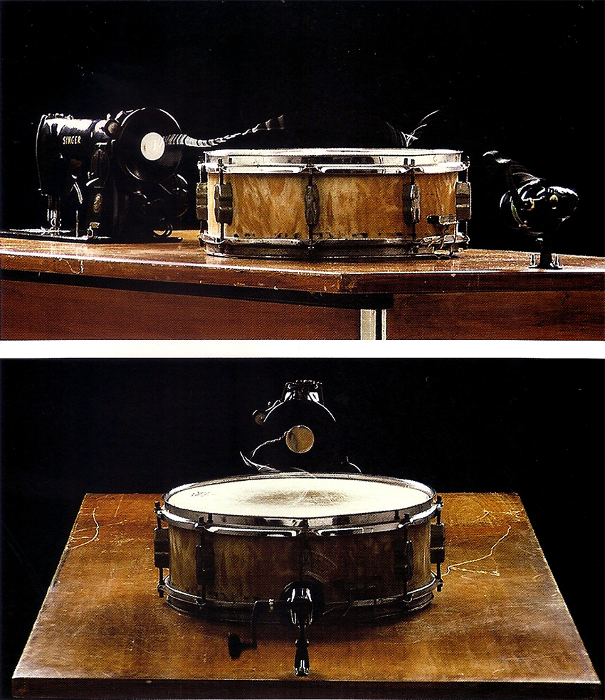
Figure 7 Chelpa Ferro, Samba (2009), table, sewing machine, shing reel and line, snare drum. Photo © Chelpa Ferro, used by permission.
Another work that exemplifies gambioluthiery as an expanded sense of the musical instrument is Tato Taborda’s Geralda (1988-2001) (figure 4). A mix of multi-instrument and electroacoustic orchestra, Geralda s essentially a one-man-band instrument, where the player activates more than 70 sound sources using hands, elbows, knees, head and feet.23 Originally designed in 1992-1993, the instrument continued to evolve over the next decade as Taborda added sound layers and incorporated or abandoned materials and devices. It began with instruments and acoustic objects, to which he later added microphones (1998-1999) and live electronics (2001). "All the technology used in Geralda has a gambiarra way of being,” Tabora says. “It's rounded. It's technology without the edges."24 With its three species of sound — acoustic, electric and digital) — Geralda embodies one possible taxonomy of gambioluthiery.
1 This chapter is a revision version of the author’s article “Gambioluthiery: Revisiting the Musical Instrument from a Bricolage Perspective,” Leonardo Music Journal 27 (2017), pp. 8792, and is based on his PhD dissertation, Gambiarra e experimentalismo sonoro. São Paulo: ECA-Universidade de São Paulo, Berlin: Technische Universität, 2014.
2 See: Lisette Lagnado, “O malabarista e a gambiarra,” Revista Trópico, São Paulo 3 (2003); Ricardo Rosas, “The gambiarra: considerations on a recombinatory technology,” SESC - Caderno Video Brasil 2 (2005): 3653; Reed Ghazala. Circuit-Bending: Build your own alien instruments15 (John Wiley and Sons, 2005); Nicolas Collins, Handmade electronic music: the art of hardware hacking (Taylor & Francis, 2006); John Richards, “Getting the hands dirty,” Leonardo Music Journal 18 (2008): 2531; Caleb Kelly. Cracked media: the sound of malfunction. MIT Press, 2009; Erkki Huhtamo. Thinkering with Media: On the Art of Paul DeMarinis. In: Paul DeMarinis/Buried in Noise (Kehrer: 2010) (2011), pp. 3346; Kim Cascone. Residualism. In: Sound (Whitechapel: Documents of Contemporary Art (2011); Rodolfo Caesar. O loop como promessa de eternidade. In: Anais do XVIII ANPPOM. Salvador (Bahia). 2008, pp. 286-290.
3 Antônio Houaiss. Dicionario Houaiss Online. Acessed 21 September 2019 , 2018.
4 Rodrigo Naumann Boueur. Fundamentos da gambiarra: a improvisação utilitária contemporânea e seu contexto socioeconômico. PhD thesis. Universidade de São Paulo, 2013.
5 Ernesto Oroza. Desobediencia Tecnológica. De la revolucion al revolico. In: Recuperado de http://www. ernestooroza.com/desobediencia-tecnologica-de-la-revolucion-al-revolico (2012).
6 Patricia Zavella, “Beyond the screams: Latino Punkeros contest nativist discourses,” Latin American Perspectives 39.2 (2012): 2741.
7 With allusions to the historic practice of cannibalism by Brazilian aborigines, the anthropophagic movement proposed by the poet Oswald de Andrade in his Manifesto Antropófago (Cannibalist Manifesto) defended a plural culture that aimed to digest everything that comes from outside. See Oswald de Andrade, Manifesto Antropófago" Oswald Andrade. Manifesto Antropofágico. Em Piratininga ano 374 da deglutição do Bispo Sardinha. In: Revista de Antropofagia 1.1 (1928) Tropicalismo exposed the contradictions of modernity in Brazil: On the one hand, the capitalist development and strong urbanization of the 1950s and 1960s (including construction of the capital, Brasília) fueled Brazil's optimism; on the other hand, Brazil was still haunted by its position of underdevelopment and economic disadvantage in relation to Europe and North America: Flora Sussekind. Chorus, Contraries, Masses: The Tropicalist Experience and Brazil in the Late Sixties. In: Tropicália: A Revolution in Brazilian Culture (2005), pp. 31-58.
8 These cultural aspects are discussed in Obici [1] and Rosas [2].
9 M. Bakhtin. A cultura popular na Idade Média e no Renascimento. São Paulo/Brasília: Hucitec, 1987[1977], p.10.
10 Roberto DaMatta. Carnavais, Malandros e Heróis: para uma sociologia do dilema brasileiro. Rio de Janeiro: Zahar, 1979.
11 In Dicionário Houaiss [3], carnivalization is described as "based on a mixture of diverse elements in which the rules or patterns (social, moral, ideological) commonly followed are subverted or set aside, in favor of stimuli, forms and contents more linked to instincts and senses, to the expansion of laughter and sensuality. Or 'condition of something that has such a mixture'" (my translation). The concept was invented by the Russian literary critic Mikhail Bakhtin (1895–1975).
12 Richards [2].
13 Paul DeMarinis. Buried in Noise. (Eds). Ingrid Beirer, Sabine Himmelsbach, and Carsten Seiarth. Berlin: Kehrer, 2010.
14 Interview made with Tato Taborda, Berlin, 2013 (personal author records).
15 See Obici [1].
16 Walter Smetak. Simbologia dos instrumentos. Salvador: Associação dos Amigos de W. Smetak, 2001[1980].
17 According to Marco Scarassatti, "Plástica Sonora Silenciosa expands the field of music to the context of space and visuality. The sound is materialized in its own plastic form." See Marco Scarassatti, Walter Smetak: o alquimista dos sons (São Paulo: SESC-SP, 2008), 98. Douglas Kahn notes that artists utilized different terms such as radio art, audio art and sound art between 1970 and 1980. See Douglas Kahn, “Sound Art, Art, Music,” The Iowa Review Web 7.1 (2005): (accessed 9 September 2018).
18 Franz Manata and Saulo Laurardes. Arte e Som no Brasil - Os primórdios. Ed. by Podcast 06 Chelpa Ferro. Online: podcast Arte Sonora. Mar. 20, 2017. url: http://exst.net/artesonora/podcasts/pod-06-chelpa-ferro/2013.
19 Paulo Nenflido In. Fred Paulino. Gambiólogos: a gambiarra nos tempos digitais. Belo Horizonte: Kludgists, 2010, p.12.
20 Giuliano Obici and Alexandre Fenerich. “Jardim das Gambiarras Chinesas: uma prática de montagem musical e bricolagem tecnológica,” Encontro Internacional de Música e Arte Sonora, Juiz de Fora-MG (2011). For more information about En Minus One (n-1), see http://n-1.art.br.
21 See: Lagnado [2] and Rosas [2].
22 Vivian Caccuri. Ouvindo as artes visuais: sonoridades de Waltercio Caldas, Cildo Meireles, Chelpa Ferro e Hélio Oiticica. MA thesis. Universidade Federal do Rio de Janeiro, 2011, p.58.
23 Geralda is similar to Acustica (1968-1970) and Zwei-Mann-Orchester (197173) by Mauricio Kagel (19312008), in which the instrumentation is a huge array of sound sources, a world of exotic instruments and almost surreal invention.
24 See [14].
A Brief Personal History of dorkbot-nyc
Douglas Repetto
I moved to New York City in the spring of 2000 to start a new job at the Columbia University Computer Music Center (CMC). Having spent the previous three years in rural Vermont and New Hampshire in relative artistic and social isolation, I was excited to jump into the cultural chaos of the city. My background was mostly in “experimental” art and music, which ideally means an openness to creative expression in any form, and an eagerness to explore ideas that are probably not going to take you to Carnegie Hall. I knew hardly anyone in New York, but I knew the place was full of weirdos, and I wanted to know them. I started a series of informal meetings called dorkbot-nyc, with the idea that people from around the city could share their experiments with one another.
In Vermont and New Hampshire I had spent most of my time with my friends and mentors, composer/performers Jody Diamond and Larry Polansky. Years ago they founded the Frog Peak Composers Collective (http://frogpeak.org), a small press and distributor of musical scores, recordings, and whatnots (including bottles of inedible artist-produced olive oil). I was moved and inspired by Frog Peak’s somewhat fuzzy mission statement:
Frog Peak Music is … committed to the idea of availability over promotion. Member artists determine which of their own works are included in Frog Peak, and how they are included... the collective… provides an example of some of the ways that artists might control their own work in a non-commercial, non-hierarchical fashion, erasing distinctions between artist and publisher.
So when I arrived in New York, I had collectives and sharing on the brain. It was a time in Internet culture when online sharing and collaboration were really taking off, as well as generating a lot of debate and controversy (remember “file sharing”?). The heroic solo hacker culture seemed to be waning, and the “sharing economy” was emerging.
In 1996 I had started, with Tom Erbe, then at CalArts, an email list called “music-dsp” for people interested in learning about musical digital signal processing. Managing that list and the strong personalities that emerged was a challenge for me, but the payoff was engaging with many people who shared my interest in exploring the possibilities of combining code and sound. I liked helping people connect and share their ideas, but now I wanted to do it in person!
New to the city, knowing no one, but hungry for in-person sharing of ideas and energy, I went to Brad Garton, director of the CMC, and proposed a series of monthly meetings where creative people from around New York City could share what they’re working on. Brad gave an enthusiastic yes. A couple years earlier the CMC had hosted what were called “bark meetings,” where composers associated with the Center would share their computer music work with one another, but that it had run its course. He was game to try again, and the CMC agreed to provide space and tech (speakers and a projector) for the meetings in crumbly Prentis Hall on 125th Street in West Harlem.
I needed a name for these meetings—something fun and casual, nerdy but not too specific. At some point I remembered “dorkbot,” a word made up by my friend Joel Fox when we were in grad school at CalArts. It stuck. I added the tag line: “people doing strange things with electricity.” That was a mistake: it should have been just “people doing strange things”— the word “electricity” made many people question whether what they were doing (with code, with bio-hacking, with live performance, etc.) qualified. Over the years I would trot out an iffy explanation that pretty much everything in our world relies on electricity in one way or another, but I wish I had rethought that phrase at the outset.
I set up a couple email lists on the CMC server: “dorkbotnyc-blabber” for general discussion of making things in NYC, and “dorkbotnyc-announce” for publicizing meetings. My prior experience running the music-dsp mailing list made me think that having a discussion list to go along with the meetings would be valuable. I imagined people sharing tips on where to buy motors on Canal Street, instructions on tapping into power on a subway platform, or asking for help with a flash mob (remember those?). It turned out that in NYC the blabber list was never super active, but later in some other cities it became an essential resource.
I put up a quick website, invented a bunch of FAQs, and we were off! I asked around a bit to see who would like to present at the first meeting, and found Brian Whitman, then a graduate student in Natural Language Processing at Columbia, and Michael Goggins, a composer and friend of the CMC. I would be the third. On December 6, 2000, we had our first dorkbot-nyc meeting. I think there were about ten people in the audience; unfortunately, no one thought to take any photos or video!
The first few meetings were small (I recall that there were seven people at one). But I was getting to know more “people doing strange things” in the city, and I was starting to build up a list of those who said they’d like to participate, so I kept organizing monthly meetings.
I was announcing the meetings on various art/tech mailing lists, which tended to have international subscribers, and from the start strangers from elsewhere in United States and from around the world emailed to say they thought dorkbot sounded interesting. At some point in that first year I received an email from Alex McLean and Ade Ward in London, who I had met at an algorithmic art conference in Milan. They had been doing similar geeky social events in London and suggested that going forward they might use the name dorkbot-london. I was amazed—it hadn’t occurred to me that dorkbot might spread! We set up a webpage and mailing lists for dorkbot-london, and they had their first meeting in November of 2001. In the next few months I received similar email requests from Jan de Pauw and Guy Van Belle in Ghent, Belgium, and Karen Marcelo in San Francisco—more dorkbots! Over the next several years nearly 80 independent dorkbots spawned around the globe. We had a mailing list called dorkbot-overlords for people organizing the various dorkbot events, and from there were hatched all manner of projects.
At the same time, attendance at dorkbot-nyc meetings was growing, and lots of people were interested in giving presentations. The small room we used at the CMC was overflowing, and I started looking for larger spaces we could use at Columbia. At each meeting I would say: “If you’d like to give a presentation, just contact me, and I’ll put you on the schedule.” Lots of people responded, but for the first several months all the presenters were male, and nearly all white.
My earnest “open to everyone” spirit was good, but the effect wasn’t what I hoped for. I learned something important that has served me well ever since: if you ask a question and the answer seems off, then maybe it’s time to rethink your question. The answer to “who will come up and tell me they should be on the schedule” was “almost no one but white men.” It was time to change the question. In addition to making my “just contact me” pitch at each meeting, I started actively reaching out to people who popped up on my radar and seemed interesting—recommendations from friends, artists whose work I admired, quiet people who came to meetings and sat by themselves. Some of my very favorite dorkbot presentations came from those invitations—like the time the very shy members of the band Neg-Fi sat at a stark black table for 20 minutes while their little feedback boxes crackled, or when Caitlin Berrigan poured chocolate into her Viral Confections molds and shared hepatitis C virus-shaped bonbons with a slightly nervous audience (yumm!).
As word spread about the meetings, people started contacting me asking if dorkbot wanted to do events, or write articles, or be on panels. I was hesitant to do too much personally as “dorkbot,” since I didn’t really feel dorkbot was anything other than an open spirit and a simple format. I always encouraged presenters to keep things informal, “as if someone at a party asked you what you’re interested in.” This helped make the presentations more accessible to a broad audience (although there were plenty of blanks stares and awkward silences), but these were by no means TED talks.
In early 2004 Claire Montgomery and Heather Wagner from a non-profit SoHo gallery called Location One contacted me to see if dorkbot and Location One might work together. It was a perfect match, since their mission was to support experimental art through installations, performances, and other public events. They had a beautiful, conveniently located space, and a friendly staff happy to help make dorkbot happen every month. It was dreamy. We had our first meeting there in April of 2004, and for the next decade Location One hosted nearly every dorkbot. Putting on events is a lot of (often thankless) work, and we would have never have survived 13 years without the support of the lovely people at Location One.
SoHo is a highly visible neighborhood, and after some friendly press exposure (including an article in The New Yorker), we started getting larger crowds, up to 150 people or so. Even when meetings got big, we still followed the same basic plan: we’d play a dorkbot theme song (people would send new ones occasionally); I’d give a quick introduction to dorkbot culture, and invite people to contact me to give presentations in the future; then we’d have three 20-minute presentations separated by short breaks. Bleep bloop blorp, we’d be in and out in 90 minutes. Afterwards I’d head to Chinatown with some friends for dim sum. What a wonderful time that was!
At the same time, dorkbot meetings continued to pop up around the world. Some really took off and had regular meetings for years. Other never quite got off the ground, or had one or two meetings and then petered out. I always said “yes” when someone asked to start a dorkbot—it was an experiment in giving up control. I’d send a document that outlined the basic concept: short, informal presentations on interesting topics; everyone is welcome; everyone can give a presentation; avoid money if possible. I’d set them up with a website and mailing lists, add them to the dorkbot-overlords list, and that was that. While dorkbot meetings in each city tended to share that basic format, there were no rules, no dues to pay, no contracts. Dorkbot was not a legal entity of any sort, and anyone could use the name. We relied on good will to keep the dorkbot spirit pumping. Sometimes I got the chance to visit meetings in other cities, or organizers from other places would come to New York and we’d get to meet in person.
There is nothing particularly original about the idea of dorkbot. People have been getting together to share work and ideas with one another for ages, whether in a cozy cave, an ornate salon, or a shabby co-working space on Broadway. Various themed meet-ups became popular in New York during dorkbot-nyc’s run, and several other sharing/social/arts organizations appeared around the same time. Something was in the air. I’m sure I’m forgetting a few, but in particular I remember share.nyc (open audio-visual jamming nights), The Upgrade! (art and technology forum), and Madagascar Institute (public art collective). There was so much happening in New York City that we never wanted for presenters or audience.
Over its thirteen-year run, dorkbot-nyc featured hundreds of presentations (as of summer 2019 at least two other dorkbots, London and San Francisco, are still semi-active.) Sometimes we attracted mainstream press or big crowds, and sometimes we managed good documentation. Often we were just 20 people in a room talking about things that seemed important. I was so fortunate to meet many kind and creative people through dorkbot, and to make several life-long friends (hi LoVid!). I ended dorkbot-nyc when I no longer felt I could do a good job of running it. Rather than try to pass it along to someone and preserve the “institution,” I preferred to make room for another idea to bubble up and take things in new directions. Our creativity is boundless—let’s share the worlds we create.

Figure 1 dorkbot.org homepage. Figure by Douglas Repetto, used by permission.
The Contact Microphone: a cultural object
Daniela Fantechi
Introduction
A contact microphone is a microphone that senses audio vibrations through physical contact with a solid surface or immersion in liquid, and converts them into an electric signal. It is an old, often inexpensive technology that has stimulated the creativity of several generations of musicians and sound-artists, precisely because of its peculiar property of activating a different way of listening. Contact microphones have been widely used to turn everyday objects into “musical instruments,” as an alternative to synthesis. Sonic exploration of the acoustic characteristics ofdifferent objects uncovered new ways to conceive sound material while revealing a different perception of the materiality of sounds. A contact microphone can be intended as a cultural object if one takes into account the connections and relationships arose between musicians and composers who have used this technology, even when their purposes and aesthetics differ.
Brief historical overview
The history of the contact microphone is related to the history of piezoelectricity, since most contact mikes have been made with piezoelectric materials.1 Piezoelectricity was discovered in 1880 by the Curie brothers, who observed changes in the surface charges of different crystals—tourmaline, quartz, topaz, cane sugar and Rochelle salt—when subjected to mechanical strain. They named the phenomenon “piezoelectricity” (from the Greek word πιέζειν piezein = press, squeeze). The inverse piezoelectric effect—mechanical strain resulting from the injection of an electrical signal—was discovered soon after. The first practical applications of piezoelectric principles appeared during World War I, most famously sonar, based on research by the French physicist Paul Langevin (previously a doctoral student of Pierre Curie) and the British/Canadian Robert William Boyle. An electric pulse was sent to a piezoelectric crystal, which produced high-frequency mechanical vibrations that were transmitted through the water. Upon encountering an object, these signals reflected back. A second piezoelectric sensor detected this reflected energy and converted it back into an electrical signal. The distance from the ultrasonic source and the reflecting object was determined by the elapsed time between transmission and reception. This technology was of strategic importance in both world wars. Years later musicians and sound-artists began using underwater microphones (hydrophones) with far more peaceful intentions.
The trickle-down of sonar technology stimulated the development of many other kinds of piezoelectric devices. After World War I, more familiar piezoelectric applications – such as microphones, phonograph pick-ups and signal filters – were invented and put into practice. During World War II, researchers in the United States, Japan and the Soviet Union replaced naturally-occurring crystals with ferroelectrics – new discovered artificial materials that exhibited stronger piezoelectric properties; these were incorporated into more powerful sonars, ceramic phonograph cartridges, piezo ignition systems, the sonobuoy (sensitive hydrophone listening and transmitting buoys for monitoring ocean vessel movement), miniature sensitive microphones, and ceramic audio tone transducers.
After World War II, Japan dominated the international market for piezo materials, manufacturing several types of piezoceramic signal filters that addressed needs arising in television, radio and communications equipment, as well as piezoceramic igniters for natural gas/butane appliances. The market for piezoelectric applications continued to grow, with the emergence of audio buzzers (such as those in appliances and smoke alarms) and ultrasonic transducers (used in motion detecting intrusion alarms and early television remote controls). More recently, piezoelectric technology has been applied in the automotive domain (wheel balancing, seatbelt buzzers, tread wear indicators, keyless door entry, and airbag sensors); computers (microactuators for hard disks, piezoelectric transformers); a wide range of other commercial and consumer devices (inkjet printing heads, strain gauges, ultrasonic welders, smoke detectors); and medical, biomedical and bioengineering applications, including insulin pumps, ultrasound imaging and therapeutics, piezoelectric and biomedical implants with associated energy harvesting.
Musical applications
Piezoelectric innovations played an important role in the development of electronic music, especially in the experimental scene from the late 1950s onward. One of the main reasons can be found in the possibilities unfolded by amplification, as Michael Nyman observes:
Amplification may reveal a previously unheard, unsuspected range of sounds, drawn out of the hitherto mute or near-mute instrument of whatever nature, bringing about both quantitative and qualitative changes in the materials amplified.2
As Nyman suggests, an amplified sound — a sound transduced from the acoustical to the electronic domain — is perceived differently not only because quiet sounds can be made very loud, but more significantly because the proximity of a microphone captures features of the sound source that were previously unheard. This shift in perception is even stronger when the microphone is a contact mike. Vibrations picked up directly from a surface sound different from the same vibrations after they travel through the air. The resonant material acts as a filter, and the contact microphone picks up the object’s “inner sound,” like a heartbeat heard through a stethoscope. Through piezoelectricity, composers and musicians started to grasp the full potential of amplification as a creative tool.
Cartridge Music – John Cage
John Cage was one of the key figures in the musical application of contact mikes and extreme amplification, as exemplified in his Cartridge Music (1960). In this early piece of live electronic music, all sounds are produced through the amplification of very small sounds, primarily using piezo-ceramic phono-cartridges from record players. Performers replace the cartridge needles with different materials—twigs, pipe cleaners, springs—and manipulate the objects by scraping, plucking, etc., to elicit different sounds, which are amplified and sent to the speakers.3 The phono-cartridges act as contact microphones used to extract new sounds from familiar objects. Cartridge Music embodies several concerns that, over the following years, would become axiomatic in much experimental electronic music. One, already noted, is the role of amplification in the production and discovery of new sounds. The sound production, moreover, is strongly connected with gestures performed on everyday objects instead of traditional instruments. Finally, Cartridge Music is representative of a certain DIY approach to electronic systems—in 1960 few could afford oscillators and tape recorders, but everyone seemed to own a record player that could be “hacked” to play this piece. These concerns were present in Cage's research before Cartridge Music. As Nyman points out, “Cage's Cartridge Music had its roots in his pre-war Imaginary Landscape No.1 (1939) which introduced a number of proto-electronic instruments, and, more relevantly perhaps, in the category of 'amplified small sounds' of William Mix (1952).”4 Indeed, Cage had experimented with amplification before Cartridge Music.5 He had also previously imported non-musical objects into the concert hall: Water Music (1952) uses whistles and radios, while Living Room Music (1940) invites musicians to use “any household objects or architectural elements” as instruments.6 But with Cartridge Music especially, Cage pointed out a different way of conceiving electronic music, bypassing the equipment of the electronic studios, and inventing and adapting portable electronic devices for improvising or performing indeterminate music.7 Cartridge Music exerted a profound influence on the younger generation of composers who started making electronic experimental music in the 1960s and ‘70s.
David Tudor and Composers Inside Electronics
With regard to the development of live electronic music David Tudor was truly a pioneer: after a pivotal role as a virtuoso pianist in the development of the post-war musical avant-garde, Tudor became one of the first live electronic performers, with a very personal approach to electronic technology, strongly influenced by his collaboration with Cage8. After assisting in the development and performances of Cartridge Music, Tudor continued to experiment with similar setups in other pieces by Cage, such as Music for Amplified Toy Pianos (1960) and Variations II (1961).9 For each of these pieces, Tudor used a set of phono cartridges to amplify the piano sounds. He gradually acquired enough knowledge and confidence to design his own electronic circuits for use in conjunction with the cartridges, and came into his own as a composer (as distinct from a performer) of electronic music.
A few years later another group of musicians – Composers Inside Electronics – expanded Tudor’s "hands-on" way of working with electronic means10. The group came together on the occasion of a workshop that Tudor gave in 1973 around his composition Rainforest in the “New Music in New Hampshire” conference in Chocorua, NH. (David Behrman, Gordon Mumma, Frederic Rzewski and several others also gave workshops at the conference). John Driscoll, Paul De Marinis, Phil Edelstein, Linda Fisher, Ralph Jones, Martin Kalve and Bill Viola were among those who attended Tudor's workshop. As Driscoll remembers:
David was holding a workshop on the idea of Rainforest and processing signals through an acoustical transformation. So he introduced us to this idea of taking a sculptural object and putting a transducer on it, holding directly to it, and vibrating that material, then a contact microphone on the object to re-amplify the signal that was in the material. It's very common now, but at that time it was not. And the idea was to discover the signals that the object like to resonate with.11
Rainforest was originally conceived for choreography by Merce Cunningham in 1968, and by 1973 the piece had already been performed in several different versions. Driscoll recounts that during the workshop the piece took a slightly different form—using bigger objects such as a wagon wheel, a wine barrel, bed springs, etc.12 The objects had to be suspended in order to resonate freely, so they were hung from the beams of a barn, creating an environment of sounding sculptures through which the audience could walk. At the end of the workshop, the piece was performed, and several of the participants asked Tudor if he would be willing to continue the project.13 The Chocorua version, later titled Rainforest IV, was subsequently performed over 125 times, in more than 45 cities.14 The group was officially dubbed Composers Inside Electronics in 1976, when Tudor was invited to the Festival d’Automne in Paris. He wanted the musicians from the Chocorua workshop to assist him on Rainforest, and in the course of the festival they also performed Cage's Cartridge Music and works by Takehisa Kosugi, as well as pieces by various members of the ensemble. The name was chosen to represent Tudor's ideas, around which the group was shaped:
David thought most music focuses on the idea that you have a musical concept and then you find the instruments to realize it, and he believed in the reverse of that: when you start with an instrument, you explore it and that suggests the music that you make. So, that was the reason behind the name Composers Inside Electronics: the ideas start inside the electronics and then became musical, the instrument suggests the music. When he was building his electronics, it was never the “normal” use of the electronics: he was making this no-input mixing, and for him, this was just a new concept to generate sounds. In the early '60s, nobody had computers, nobody had access to the labs of electronics, nobody had synthesizers, and David sort of explored that world trying to use the electronics to make the music he was interested in.15
In the beginning, crystal phonograph cartridges were used as contact mics in Rainforest's realizations. Tudor was familiar with them from his work on Cartridge Music. Driscoll remembers the Astatic 12u (figure 1), whose the needle was inserted in a hole in such a ways that it could be replaced by a piece of steel wire, creating a less fragile contact point. Later, when this type of cartridge became hard to find, the group started experimenting with other kinds of contact-mics, such as throat-microphones and bone transducers (put against the jaw to conduct sound via bone to the inner ear)—often used by people with hearing. The group’s collection also included disk cutterheads (devices for cutting records, here used in reverse as microphones) and microphones used for listening to the heartbeat of a foetus (figure 2). Using so many different types of device created challenges, Driscoll recalls. “Each kind of microphone needed a specific pre-amplifier, with a specific circuit.”16 When piezo disks became available, they were used as well, though they usually have a peaked resonant frequency, whereas the cartridges were have a gentler curve and when you put a reverse curve in your pre-amplifier you could bring out a lot of the bass.
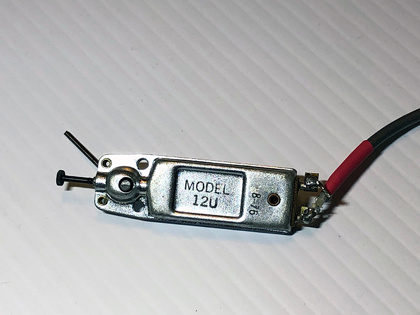
Figure 1 Astatic12u, phono cartridge. Photo © John Driscoll, used by permission.
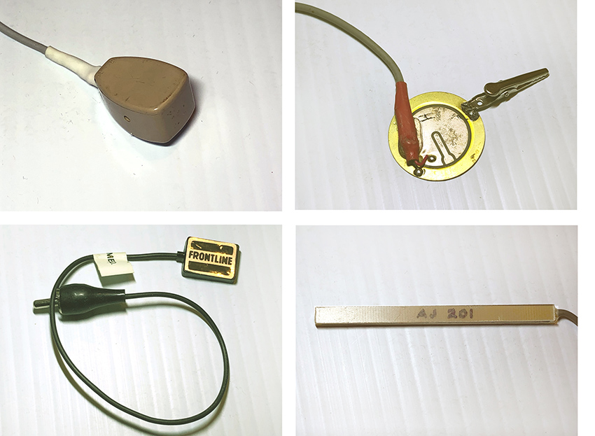
Figure 2 Different contact microphones from the collection of John Driscoll. Clockwise from top left: small throat mike; piezo piano pickup; homemade piezo pickup; Frontline pickup. Photos © John Driscoll, used by permission.
Richard Lerman
Richard Lerman contributed significantly to the research on the musical use of contact microphones. He began experimenting with different kinds of contact microphones in the mid-1960s, using them to record sounds made by “wind harps, plants, boat anchor ropes, rocks, cactus thorns, heat expansion in metal, spider webs (with limited success). He attached them to many kinds of self-built and traditional musical instruments, and even used them as loudspeaker drivers to induce sound into metal and glass sculpture.”17 Lerman was studying at Brandeis University in Waltham, Massachusetts, when Alvin Lucier was running the electronic studio there (with Anthony Gnazzo). When Lucier left Brandeis for Wesleyan University, Lerman — “vastly unprepared but really curious” became the technical director of the studio by default.18 According to Lerman, during that period John Cage and David Tudor were often around, as well as Gordon Mumma, from whom he learned to solder. Lerman remembers Tudor telling him, "Richard, if you want to do electronic music, you have to learn some electronics." Taking the words seriously, Lerman was “early in the game” using piezo disks both as microphones and loudspeakers (or, as he puts it, “soft speakers”). The first versions of his piece Travelon Gamelon (1977) used “phono cartridges between fender washers, housed in the plastic box that [the cartridges] were packaged in.”19 Suggesting the percussive, metallic timbre of a gamelan orchestra, the sounds in Travelon Gamelon were produced by the rhythmic movements of bicycles captured by contact mics. The cartridges were fragile, and even in protective plastic housings, they often broke. So Lerman started experimenting with piezo materials:
I was researching a lot of different sources about phono cartridges and discovered that ceramic cartridges (EV 81T's) were piezo devices and were usually made from something like barium titanate. Seeing the word “piezo” with “disks,” maybe from a company in Massachusetts called Meshna Electronics, I started buying up different kinds of disks. These were much easier to work with than with the phono carts. So I began using the piezos probably in '78 / '79 or so. They were much more rugged once I figured out the best way to solder them. I began in earnest to work with the disks and to construct preamps for them using various op-amps that were around.20
Materials for such DIY projects were available from electronic surplus dealers, as well as from hobby retailers such as Radio Shack, and manufacturers such as Electro-Voice, Kent, Astatic, and Barcus Berry (figure 3).
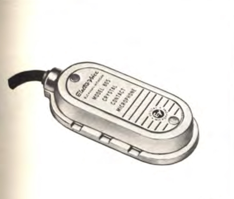
Figure 3 Contact microphone 805-ElectroVoice, pictured in a 1957 Electro-Voice catalog 1957). In the catalogue the microphone is described as “Contact—For guitar, banjo, any vibrating-string instrument. Hi-Z. Sealed crystal. Chromium finish. 15-foot cable. List Price ...$20.00”.
At the same time, European avant-garde composers were developing electronic works, mostly recorded onto tape in radio studios, such as WDR (Köln, Germany), ORTF (Paris, France), Studio di Fonologia (Milano, Italy), and BBC Studio (London, UK).21
Mikrophonie I – Karlheinz Stockhausen
Karlheinz Stockhausen explored live electronic processing in his pivotal work, Mikrophonie I (1964).22 The only sound source is a large tam-tam gong that is excited with objects of different materials—glass, cardboard, metal, wood, rubber and plastic. The performed actions are amplified with a strongly directional microphone and then processed in real-time. The six performers are divided into three groups: the first two play the tam-tam, the second two manipulate the microphone, while the third pair modulate the microphone's sound with a filter and a potentiometer. The distance and location of the microphone affect the clarity and the timbre of the sound, in much the same way physical location affects the sound heard through a contact mike. With the help of Jaap Spek, the technician at Cologne’s WDR radio, Stockhausen had started using contact microphones (figure 4) to amplify the metal and string sounds in many of his pieces, including Mixtur (1964), Prozession (1967), and Kurzwellen (1968).23 The latter two were performed several times by the composer and violist Johannes Fritsch, who was part of the Stockhausen Ensemble (1964-1970), together with Rolf Gehlhaar. Fritsch and Gehlhaar continued to experiment with contact mics after they left Stockhausen's group and formed the Feedback Studio (active between 1971 and 2001). Gehlhaar remembers Fritsch using a piezoelectric contact microphone manufactured by Schaller for Fritsch’s piece Partita (1966) for amplified viola and tape delay:24
Normally, when he played, he had the microphone attached either to the bridge [of the viola] or to the soundboard very close to the bridge. The position varied with what quality of sound he wanted to produce —on the bridge, brighter, sharper sound; on the soundboard, slightly more muffled, rounder sound. . . The Schaller contact microphone was very useful for installations and theatrical applications, where, for example one could be attached to the clinking chains that an actor was wearing as a part of his costume . . . In the Feedback Studio we experimented a lot with the contact microphone and various instruments as well as surfaces in our installations of the early 70s, where we would turn whole rooms and all the objects with them into musical installations. For this purpose I often found the contact microphone too sensitive or difficult to employ. I began to research other ways of amplifying objects, for example by hanging them on steel strings passing over an electromagnetic guitar pickup. This produces very interesting sounds. Another technique I developed for installations was to employ piezoelectric emitters as microphones by placing small weights on them, one edge on the piezo, the other on the object to be amplified. This works very well.25
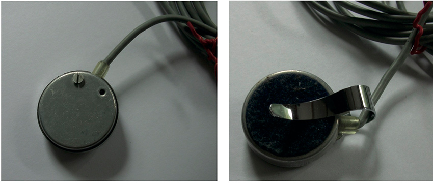
Figure 4 Contact microphone used by Stockhausen Ensemble. Photo © Sean Williams, used by permission.
Hugh Davies
Hugh Davies (1943- 2005), a British composer and early advocate of live electronics, invented more than 130 concert instruments, sound sculptures and site-specific installations, many of which made use of contact microphones of various types. He was strongly influenced by his experiences as Stockhausen's assistant between 1964 and 1966, including his participation in the first performances of Mikrophonie I under Stockhausen’s direction.26 The role of amplification and everyday objects in this piece had a profound effect on Davies, marking the point from which he abandoned tape music to concentrate on live electronic music. When he returned to the UK in 1967 he began building his own instruments, recycling everyday objects, applying contact microphones, and foregrounding sounds that were not usually part of the musical realm.27 In these projects, Stockhausen’s influence was balanced by that of Cage and Tudor, especially in regards to the low-fidelity aesthetics and DIY ethos employed in realizing his instruments, as well as the freedom to combine more diverse sound sources. 28 In 1968 Davies created Shozyg I (figure 5), which consists of a book whose pages had been hollowed out to make space for objects mounted inside its back cover. The objects—a ball bearing, three fretsaw blades of different lengths and two different springs—were grouped in two areas, each group amplified by a piezoelectric pickup, chosen according to its filtering characteristics. The objects were played using fingers, fingernails, screwdrivers, needle files, toothbrushes, small electric motors, etc.29
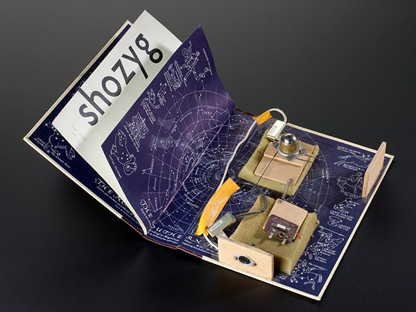
Figure 5 Shozyg I (1968), self-built electro-acoustic musical instrument by Hugh Davies. © Science Museum/Science & Society Picture Library, used by permission.
Between 1968 and 1975 Davies was a member of Gentle Fire.30 Beside performing compositions by living composers such as Stockhausen, Ashley, Cage, Cardew, Feldman, Wolff, etc. Gentle Fire performed collective pieces composed by the group between 1970 and 1973, which further explored live processing of sound as well as invented instrumentation. In Group Composition III and IV the ensemble shared a single instrument invented by Michael Robinson, the gHong, which was made up of three metal oven racks and a wooden crossbar on the fourth side from which four large springs were suspended.31 Each side of the gHong was connected to two contact microphones: one of high-quality, such as a stethoscope or transducer, the other a contact microphone with a reduced frequency response. By varying the balance for each pair of microphones on a mixer it was possible to obtain substantial filtering effects, so the use of microphones was crucial in the playing of the gHong.32
The Artaudofoon – Peter Schat
The idea of amplifying metal sounds with contact microphones was also applied by the Dutch composer Peter Schat (1935-2003). Early in his carrier, with the help of sculptor Frans De Boer-Lichtvelt and technician Jo Scherpenisse, he designed an instrument called the Artaudofoon. In the '60s Schat was part of a group of politically engaged young composers that included Misha Mengelberg, Louis Andriessen, Dick Raaymakers, Jan van Vlijmen, Reinbert de Leeuw and Konrad Boehmer, who founded the Studio voor Elektro-Instrumentale Muziek (STEIM).33 Nico Bes, who began working at STEIM in 1971, recalls one of his first experiences with contact microphones was the Artaudofoon.34 Inspired by Antonin Artaud’s Theatre of Cruelty, it consisted of five metal sculptures whose sound was amplified by contact microphones attached to them. According to Schepernisse, Schat used the throat-microphones used by helicopter-pilots.35 The exact origin of this huge instrument is unclear. According to Schat's biographer, Bas van Putten, the idea first arose in 1965 while working on his opera Labyrinth, when he thought of building a huge electro-acoustic percussion instrument, equipped with many “contact microphones, a filter, a modulator, an amplifier and a set of loudspeakers.”36 In September 1966 Schat tried to get funding from Philips because of technical problems and the high cost of electronic parts, and he received a commission that year from the Rotterdam Art Foundation for a theatrical work, Electrocution, which would use the Artaudofoon as a percussive instrument, but the work was never written. Van Putten, however, mentions the 1966 movie by Frans Weisz, The Gangster Girl (Het Gangstermeisje), which includes a concert scene filmed in the Kleine Zaal of the Concertgebouw and featuring a composition played by the Artaudfoon and three double basses (figure 6). 37, 38
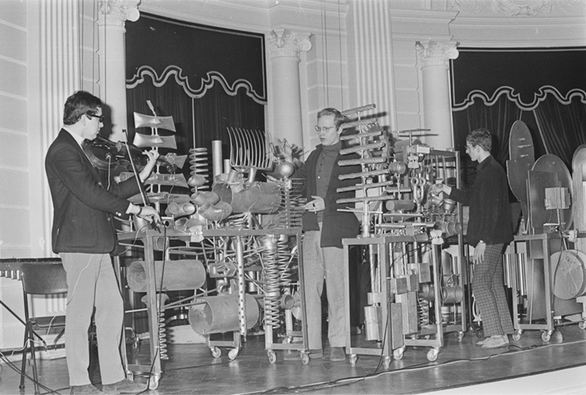
Figure 6 Artaudofoon,Peter Schat standing in the middle. Presentation of the new percussion instrument in the Concertgebouw in Amsterdam, 1966.This picture appears with this caption in the online Memory of the Netherlands Database, with the date of 14 March 1966. A similar picture was published in the San Francisco Examiner on 17 July1966, mentioning the Artaudofoon as the percussion instrument “unveiled last week,” but without specifying the occasion in which the picture was taken. It remains unclear whether the picture was taken during the shooting of the movie - since the location seems to correspond – or during another occasion.
It is possible that the bit of music played in the movie was an improvisation or an open-form composition, such as the one published in 1967 by Donemus. The latter, titled First Essay on Electrocution, for violin, guitar and metal percussion instruments (three players), seems to have been a work in progress, as can be deduced from Schat's request to settle the fee, unusually written in the score, right before the technical notes.39 In the technical notes Schat wrote: “it is the best to use the Artaudofoon for the performance […] it is, however, also possible to use cymbals and other metal percussion instruments, the sound of which is scanned with contact microphones,” suggesting that he was becoming aware of the difficulties in using the Artaudofoon. Indeed, the project was soon abandoned and the Artaudofoon forgotten.40 One instrument is still archived at STEIM (figure 7).
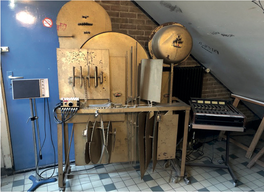
Figure 7 One part of the Artaudofoon archived at Steim. Photos © Nico Bes, used by permission.
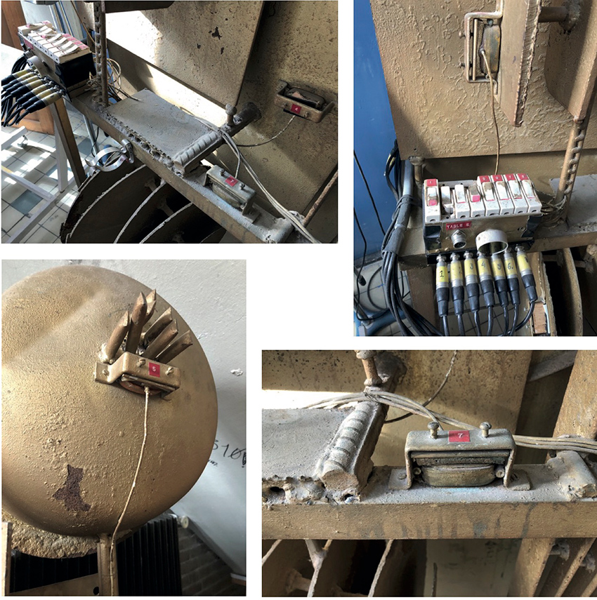
Figure 7 One part of the Artaudofoon archived at Steim. Photos © Nico Bes, used by permission.
Conclusions
The diverse experiences described are united by a shared interest in the possibilities of amplification and of new ways of experiencing sound through the use of contact microphones. The 1960s, ‘70s and '80s were a time of lively circulation of ideas. Long before the Internet made this kind of sharing effortless, international festivals and concerts offered occasions for musicians to meet and share each other's work and technical research. American composers travelled throughout Europe, bringing new ideas from the New World. Cage and Tudor were among the earliest, and had a profound effect. Tudor in particular acted as a bridge between American and European communities. Beginning in the 1950s, he premiered works by composers including Stockhausen, Maderna and Boulez, building strong connections with the European avant-garde.41 At the same time, he often toured with Cage, introducing new music from other American composers as well. It is worth noting, that the premiere of Cartridge Music took place in Germany (with Stockhausen present in the audience) at Mary Bauermeister's Cologne atelier, on 6 October 1960.42
In the following years, a younger generation of American composers participated in festivals and concerts in Europe, contributing to the development of an international community. Richard Lerman recalls that his first trip to Europe was in 1979 for the Muzicki Biennale Zagreb, where he performed Travelon Gamelon. At the 1981 Spiel und Klangstrasse festival in Essen, Germany, run by percussionist Michael Jüllich, he met Godfried-Willem Raes.43 A Belgian artist who worked extensively with piezoelectricity, Raes had been running Logos, a venue for experimental music in Ghent, since 1968.44 Lerman had his first performance there in September 1981. 45 Hugh Davies also had contact with Raes, who purchased a Springboard from Davies' collection of self-built instruments in 1974 (figure 8).
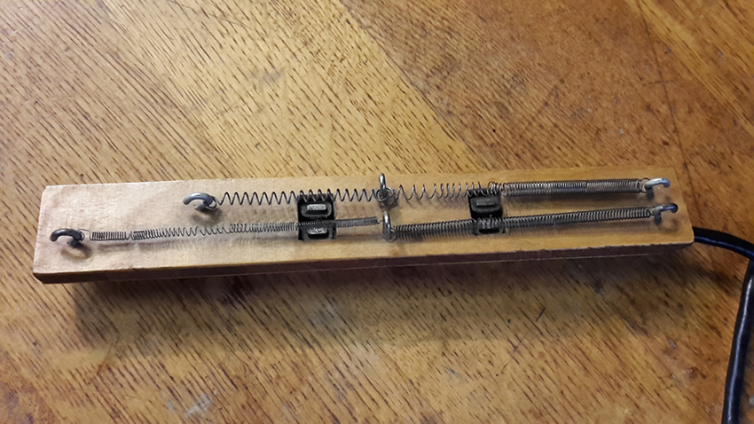
Figure 8 Springboard by Hugh Davies, owned by Godfried-Willem Raes. Photo taken at Logos Foundation by the author (20/03/19).
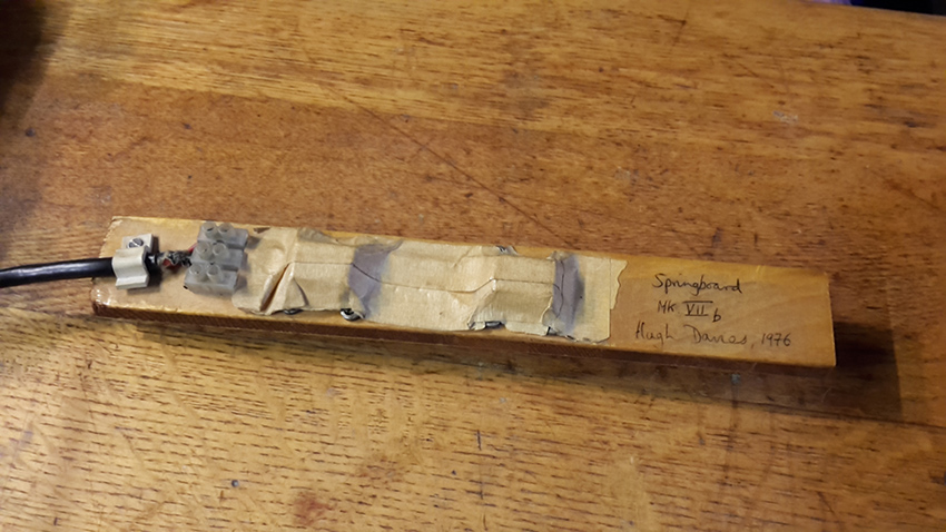
Figure 8 Springboard by Hugh Davies, owned by Godfried-Willem Raes. Photo taken at Logos Foundation by the author (20/03/19).
In such an interconnected community, the exploration of new possibilities of amplification contributed to new attitudes and practices of music making. As John Driscoll noted, Tudor's idea of inverting the role of the instrument in the process of music creation had a profound influence on the development of experimental music. The instrument was no longer the means to realize a musical idea, but became itself the starting point of a whole creative process. The possibility of amplifying the previously inaudible encouraged new perspectives, contributing to more creative approaches in the development of DIY practices and collaborative works. Because of its relevance to this process, a technological artifact—the contact microphone—became a cultural artifact, contributing to the cross-pollination between different artistic disciplines. In this context the gradual shift of David Tudor from his role as the representative pianist of the avant-garde, to that of creator and ambassador for a personal, exploratory way of dealing with electronics, exemplifies the path of a musical movement—enriched by experimentalism, through personalities such as Hugh Davies and Richard Lerman, and the collective activities of groups such as Gentle Fire, Feedback Studio and Composers Inside Electronics.
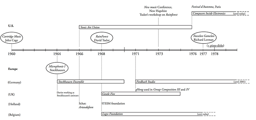
Figure 9 Timeline of the contact microphone.
1Other contact microphones are electromagnetic, employing the same principle of a guitar pickup with the difference that electromagnetic contact microphones include a metal diaphragm to transduce any physical vibration into a distortion of the electromagnetic field, while the guitar pickup is merely a coil detecting the field distortions induced by the vibrating ferric material of the string.
2 Nyman, Michael (1999). Experimental Music: Cage and Beyond, Cambridge : Cambridge University Press, p.92.
3Cartridge Music has an open form. The score consists of a number of transparent sheets, and the patterns drawn on them provide only the means to determine a time structure. Each performer has to superimpose the transparencies and work out the time structure by observing the ways in which the drawn lines and patterns on the sheets intersect. The choice of objects and means of manipulation are left entirely to the musicians. See sidebar “John Cage – The Father of Invention” in chapter 7.
4Nyman (1999), op. cit., p.90.
5See also Imaginary Landscape No. 2 (1942) in which both instruments and electronic devices are amplified through contact microphones.
6In the performance notes Cage offers examples of objects that might be employed: “1st player — magazines, newspaper or cardboard; 2nd player — table or wooden furniture; 3rd player — largish books; 4th player — floor, wall, door or wooden frame of window” (Cage, John (1940) Living Room Music, Peters Edition).
7See Nyman (1999), op. cit., p.89.
8See sidebar “David Tudor and Rainforest” in chapter 8, and You Nakai’s and Michael Johnsen’s essay on the website.
9See: Iddon, Martin (2015). John Cage and David Tudor, Correspondence on interpretation and performance, Cambridge University Press, pp.187-186.
10See sidebar “Composing Inside Electronics” in chapter 15.
11Skype interview with John Driscoll, 25 March 2019.
12As Driscoll explains, in the early iterations of the piece, Tudor used small objects on a table top, and specific homemade electronics with feedback oscillators. “The acoustic output of those small objects was not very loud, but the signal that was sent to the loudspeakers was quite loud” so listeners were hearing through the loudspeaker system, rather than hearing the object itself. (Driscoll, Skype conversation – 25/03/2019).
13“Bill Viola made an arrangement in Syracuse with the Everson Museum, and Ralph Jones found an opportunity in Buffalo”. Ibid.
14Ibid.
15Ibid.
16Ibid.
17In A Guide for working with Piezo Electric Disks to introduce Children to Issues of Acoustic Ecology and Sonic Creativity http://www.public.asu.edu/~rlerman/PDF%20Files/Children%20&%20Piezo%20disks.pdf accessed 15 April 2019.
18Email from Richard Lerman (26 September 2018)
19Ibid.
20Ibid.
21In France in the 1940s, Pierre Schaffer had already started the Groupe de Recherches Musicales at the Radio Diffusion Télévision Française (RTF), where he been working almost ten years. A few years later, Karlheinz Stockhausen was working in the WDR studio in Cologne, and Luciano Berio at the Studio di Fonologia in Milano, etc. Cage worked at Studio di Fonologia in Milan from November 1958 until March 1959, and composed Fontana Mix (1958) there.
22Mikrophonie I was premiered on 9 December 1964 in Brussels. The piece resulted from Stockhausen's experiments in the summer of 1964 on the large tam tam that he had previously bought for Momente.
23These contact mics might have come from the WDR Studio, as did most of the equipment Stockhausen used.
24Schaller contact microphones are still produced today. The most popular model is the Schaller Oyster S/P https://www.thomann.de/gb/schaller_oyster_723.htm accessed 13 May 2019.
25Email from Rolf Gehlhaar 28 April 2019.
26The collaboration started because Davies was writing about Stockhausen. The book was never published, but Davies maintained a working relationship with Stockhausen lasting several years. He continued to correct Stockhausen’s scores and perform his works in the UK.He may also have been aware of Fritsch and Gehlhaar’s experiments with contact mics, as they were in Stockhausen’s ensemble at this time.
27After Cologne, Davies moved to Paris and then New York, working on compiling the Répertoire international des musiques électroacoustiques (International Electronic Music Catalog) (RIME), published in 1968. Back in the UK he founded the electronic music studio at Goldsmiths College, which he directed until 1986. In 1982, Davies set up a small studio at Oxford University, helped by Daphne Oram, one of his mentors as a student. [For further info see also Palermo 2015, op.cit.]
28Davies recalled a remarkable concert in London by Cage, Tudor and Mumma in November 1966 during a visit by the Merce Cunningham Dance Company. They may have performed Music for Amplified Toy Pianos (1960). [See Davies, 2001]. About Davies’ own materials, Fiorenzo Palermo remembers: “The first magnetic pick up he used was around 1969 and came from ex-RAF microphones, which he claimed had been used in Spitfires during the Second World War. Subsequently, when the supply of these diminished (he got them from stores in Denmark Street in London), he turned to old telephone handset earpieces or headphones used by the military or by telephone operators. I don’t think Hugh built his own microphones, but rather salvaged and repurposed them. Nonetheless, I have found in my research that in the occasion of a performance of Sternklang by Stockhausen in Bonn in 1980 Hugh played an A clarinet with a self-made contact mike and pre-amplifier.” Email from Fiorenzo Palermo (25 May 2019).
29For a more detailed description and pictures see Palermo 2015, op.cit. Palermo specifies that Davies had begun using piezoelectric microphones “at least since the establishment of the Goldsmiths Electronic Music studio in 1967, which had two piezos in its initial equipment, and he used these to amplify all kinds of objects (combs, broken light bulbs, springs), recording Galactic Interfaces as a result.” Email from Fiorenzo Palermo (25 May 2019). In other works Davies used magnetic pickups: Concert Aeolian Harp was built from egg slicers “by mounting the fine fretsaw blades on an aluminium frame, which would have then been fixed to a stand. The blades were arranged in parallel and microphones placed at the extremity of the aluminium frame that ran perpendicular to the blades. To play the Concert Aeolian Harp, the performer blew on the fretsaw blades, producing a quality of sound similar to an Aeolian harp. [Palermo 2015, op.cit., pp.191-192].
30The other members were Richard Bernas, Patrick Harrex, Graham Hearn, Stuart Jones, Richard Orton and Michael Robinson. The name Gentle Fire arose from consultating the I Ching about the path they should take: “hexagram No. 37, the Family, came up’ the two trigrams of which are Sun and Li, meaning Gentle Wind and Clinging Fire respectively—indicating clearly to the group that they should continue these activities and supplying the name Gentle Fire” (Davies 2001, op.cit. p.54).
31In Group Composition III the gHong was the only sound source, while in Group Composition IV each member chose another additional instrument to play.
32According to Palermo [Palermo, op.cit., pp.138/140] the gHong was originally meant to satisfy the score instructions of Christian Wolff, the score instructions read: ‘Construct an instrument, or find something, or use an instrument as part of a construction which can make 5 different pitches, or 11 or 3 different pitches; 6 different qualities of sound (they can be made to depend on the manner of performance), or 2; and which can sustain sounds at least somewhat before they begin to fade’, and the different microphones placed on the instruments allowed for an extension of the sounds produced.
33See Otto, Andreas (2008). Die Entwicklung elektronischer Musikinstrumente am Steim (Studio für elektro-instrumentale Musik) im Amsterdam seit 1969. (MagisterArbeit), pp.14-15. https://docplayer.org/2117578-Die-entwicklung-elektronischer-musikinstrumente-am-steim-studio-fuer-elektro-instrumentale-musik-in-amsterdam-seit-1969.html accessed 18 April 2019.
34Email from Nico Bes, 5 February 2019.
35Email from Jo Schepernisse, 9 April 2019.
36See Bas van Putten (2015). Alles moest anders. Biografie van Peter Schat, Amsterdam: Uitgeverij De Arbeiderspers, 2015, p.381. Labyrinth was premiered at the Holland Festival 1966, conducted by Bruno Maderna, then guest director of the Concertgebouw
37According to van Putten, Schat played two roles in the movie: “the Stranger," who falls in love with the title character, and the conductor of his own music for Artaudofoon (see Van Putten 2015, op. cit., pp.386-389).
The Gangster Girl (Het Gangstermeisje) is available at the Eye Filmmuseum (info about the movie at: https://www.eyefilm.nl/en/collection/film-history/film/het-gangstermeisje) and the instrument Artaudofoon is shown in the above-mentioned scene between 16'30'' and 18'30''.
According to van Putten, Schat played two roles in the movie: “the Stranger," who falls in love with the title character, and the conductor of his own music for Artaudofoon (see Van Putten 2015, op. cit., pp.386-389).
38Fig.6 was found in the online Memory of the Netherlands Database, with a date of 14 March 1966. It is possible that the picture was taken during the shooting of the movie, since the location appears correct. The caption of a similar photograph published in the San Francisco Examiner on 17 July1966 mentions the Artaudofoon as the percussion instrument “unveiled last week,” but does not specify the occasion in which the picture was taken.
39“Here is the composition written as result of your commission. I hope that you will in the near future pay the second half of my fee, namely 750 guilders, into my transfer account (No. 122,747) Thank you very much.” (In Schat, Peter (1967) First Essay on Electrocution, for violin, guitar and metal percussion instruments (3 players). Donemus [score]).
40Idem.
41Tudor premiered, for example, Stockhausen's Klavierstück XI, in New York on 22 April 1957,(to the disappointment of Wolfgang Steinecke, who had agreed to a world premiere in Darmstadt a few months later), and Bruno Maderna's Piano Concerto on 2 September 1959 with the Heissischer Rundfunksymphonic orchestra. See: Iddon (2013), pp.181-183.
42See Iddon (2015), p. 166. The performers included Nam June Paik, Hans G. Helm, Benjamin Patterson, William Pearson, Kurt Schwertsik, Cornelius Cardew, alongside Cage and Tudor.
43Email from Richard Lerman (12 May 2019).
44Raes focused on piezoelectric elements in systems using ultrasonic motion detectors, but he also made works using piezoelectric microphones to amplify objects. In Holosound, from the early 1980s, piezoelectric elements were used to build an ultrasound system of gestural sensors, and also in the sound-producing component: the ultrasound demodulated trigger objects such as springs and chimes attached to piezoelectric microphones, so that the movements of the objects could be amplified, producing sound.
45http://users.telenet.be/stichtinglogos/concerts/concerts1981.html and http://users.telenet.be/stichtinglogos/concerts/concerts1968.html accessed 24 June 2019.last access 24 June 2019.
David Tudor
You Nakai and Michael Johnsen
David Tudor (1926-1996) was thirty-two years old when he began delving seriously into electronics. He already had an extraordinary career by that time, first as a brilliant young organist in his native Philadelphia, then switching his instrument and establishing himself as the most prominent pianist of the avant-garde in both America and Europe throughout the 1950s. His virtuosity was to such an extent that composers started writing specifically for him rather than for the piano, while his love of puzzles motivated them to explore new forms of graphic notation that required the performer to determine the specific details of the performance. After engaging in such activity for seven or so years, however, Tudor grew weary of the same kind of works composers around the world were sending him. Following a brief instruction that the Swedish composer Bo Nilsson had almost inadvertently included in the score of Quantitäten, he began amplifying his piano in 1958.
Incorporating electronics shifted the nature of piano from a percussion instrument to a resonant chamber whose characteristics could be explored especially through the use of feedback. Tudor became fascinated at the new possibilities. He began to peruse popular electronic magazines, collect amplifiers and record cartridges, and taught himself to read schematics and to solder. Soon he was amplifying many other things besides the piano. His friend John Cage followed suit and started writing pieces that involved amplification for Tudor to perform. Tudor on his part became friends with younger musicians who were more well-versed in technology, most importantly with Gordon Mumma, who he later acknowledged as having helped him get over his fear of electricity.1 By the mid-1960s, Tudor had developed a distinct kind of live-electronic music in which modular devices , homemade and commercial electronic gear as well as acoustic instruments and objects, were tentatively assembled to form a compound instrument of his own design for each performance. The modular nature allowed Tudor to “compose” the degree of control he had over the set-up, and as a consummate virtuoso, he preferred to push things to the edge of control and keep the situation indeterminate. In addition, it was customary for Tudor to switch some components from one performance to the next so that the configuration was always new and challenging.
This approach influenced a whole generation of younger musicians, as Alvin Lucier recalled: “Tudor made all his devices with inexpensive electronic components, everything he used was home-made. That was very inspiring. The development of experimental music in the United States, that phase of it anyway, started with David Tudor’s table of electronics.”2 At the same time, the specifics of what was happening inside each component on the table remained hidden, for Tudor tended not to discuss how he made his music even to his closest collaborators. Although inspired by his instruments, Lucier also admitted, “nobody knows what they are!”3
But Tudor did leave behind an enormous amount of materials which are now archived in different institutions. The bulk of his paper materials and recordings are kept at the Getty Research Institute (Los Angeles, California), while Wesleyan University (Middletown, Connecticut) houses the instruments which number up to approximately 500. About half of these are commercial equipment, mostly guitar effect pedals which he began using in the 1970s, but the collection also includes many transistor mixer-amplifiers from the late 1950s. The rest are homemade instruments, built either by Tudor himself (around 150 of these) or by acquaintances and friends. His own instruments are shrouded in mystery since almost none of them carry any labels explaining what they are, or what each of the jacks and knobs does. But since he kept notes of everything, it is possible to figure things out by matching the instruments at Wesleyan with the schematics at the Getty as if they were pieces of a giant inter-coastal puzzle (an oddly pertinent research method given Tudor’s devotion to puzzles). This procedure has indeed revealed many things about Tudor’s instruments and his music that was unknown until now.
For one thing, Tudor never designed circuits from scratch. Similar to how he used other composer’s scores as “material” (which is how he called them) in his pianist days, all the electronic instruments he built had a source, according to which they can be largely grouped into three types: (a) articles from popular electronics magazines and books, (b) schematics from friends, most importantly Mumma and Lowell Cross, and (c) rehoused kits. And just as he was known to be meticulous when realizing the graphic scores, it was customary for Tudor to follow precisely the instructions given to him when building an instrument.
The period Tudor made his own instruments was limited roughly to the ten years between 1965 and 1975. The particular things he built was always tied to some specific interest he was pursuing, which in turn was connected to a specific work or a series thereof. It is therefore possible to group his instruments into families that share related purpose, function, or style.
A) Simple circuits and kits housed in plastic cases (many soapboxes). These were the first series of instruments Tudor made, and they include several amplifiers, a clipper, a harmonic generator, a reverb, and a square wave oscillator. Most of them were made for Bandoneon ! (read as“Bandoneon Factorial”), Tudor’s contribution to 9 Evenings: Theatre and Engineering in October 1966. In this seminal piece, the first one he signed his name as a composer, Tudor aimed to make a giant noise generator using the network of instruments that processed and distributed the sound of his bandoneon (an accordion-like free-reed instrument central to Argentine tango music) across the 20,000 square feet space of the 69th Regiment Armory serving as a massive resonant chamber. His electronic set-up indeed focused on imparting additional harmonics and inharmonics to the sound of the acoustic instrument, multiplying its spectrum density to approximate white noise. The same sound was also used to control the lights and visualized on magnified oscilloscopes made by Lowell Cross. In addition, remote-controlled carts moved around objects which had been converted into “instrumental loudspeakers” with distinct resonant characteristics by attaching transducers to them, a development of his initial interest in the conversion of piano into a resonant chamber through electronics.
B) Oscillating amplifiers. Soon after Bandoneon !, Tudor purchased amplifiers (at least three Roundhill AA-100 with a gain of 70 dB), which he housed in black phenolic boxes and brought its inputs and outputs (a selection of two impedances for each) out to the surface of the panel. By wrapping feedback around these ports, and inserting resistor and capacitor substitution boxes and other passive components in the route, Tudor obtained a variable oscillator. These were originally made for Rainforest, Tudor second piece premiered in March 1968 which developed the principle of “instrumental loudspeakers” into a separate piece for Merce Cunningham’s choreography of the same name. They were subsequently used in many different configurations throughout the 1970s.
C) Phase-shifters and splitters. Tudor started building many of these in 1968, soon after the premiere of Rainforest. It appears that this was an effort to reproduce the two out-of-phase signals of the bandoneon with electronics for his collaboration with Cross where he continued to work on the visualization of sound, first with a converted television set and later with a laser system. Towards the end of the decade, the same phase shifters were inserted into the feedback path when Tudor enlarged the mechanism of the oscillating amplifiers to create entire configurations of modular electronics arranged in a loop. This “giant oscillator” became central to the lineage of no-input feedback works in the 1970s including Untitled and Toneburst. Tudor’s approach to feedback was inherited as the core technique of the later movement of “no-input mixing” and certain Japanoise.4
As the number of components kept increasing it became a burden for constant touring as well as performance. Tudor solved the problem by replacing a part of the set-up with the recording of its output. But this shift of instrumentation yet again shifted his focus. Instead of sculpting the sound that the giant oscillator spews out semi-automatically through feedback, he became more concerned about the parallel processing of a sound source which made one sound appear as many. To pursue this interest, Tudor began purchasing commercial guitar pedals in the mid-1970s, whose market was in bloom around then. He consequently made fewer instruments of his own.
As the term “instrumental loudspeakers” suggests, Tudor’s approach to any instrument was focused on its specificity. Feedback was a good method of exploring these specific principles, as returning the output of a system to its input brings out and intensifies the inherent characteristics of that system.
At the same time, Tudor opted for modularity, creating miscellaneous networks of instruments mixing old and new ones, as well as those made by himself and others. Therefore, the specific nature of any component was also influenced by what it was connected to in the set-up. For Tudor, this compound instrument also included the particular space where music was being performed. Here we can detect the influence of organ, Tudor’s first instrument, which is always coupled with the architecture of the church in which it is placed, and which enwraps the performers and listeners. This influence also led Tudor to enlarge the mechanism of specific electronic device to a large scale, as with the giant white noise generator of Bandoneon !, or the giant oscillators of no-input feedback works. The instrumental loudspeakers of Rainforest can also be regarded as giant filters, and Tudor likened his later endeavor of making one source appear as many to a “giant reverb.” In 1970, Tudor worked with the Experiments in Art and Technology to turn the entire Pepsi Pavilion into an instrument at the Osaka Expo, and he subsequently spent more than a decade trying to transform an entire island into an instrument in order to examine the maximum scale for feedback to occur. This proposed piece, Island Eye Island Ear, was never realized, but Tudor appears to have regarded it as his most important work.
1 “I am a person who is terrified of electricity. I knew nothing at all about it. And Gordon [Mumma] helped me get over that. Now I have a lot of experience related to that but I’m still terrified, you know. In a way, it’s always going to terrify me. But it doesn’t deter me from working at it.” (Charles Amirkhanian, John Cage, Takehisa Kosugi, Gordon Mumma, Michael Pugliese, and David Tudor, “A Kind of Anarchy: Merce Cunningham and Music (September 19, 1989) [videorecording],” MGZIDVD 5-469, Merce Cunningham archives, New York Public Library.)
2 Lucier, “Thoughts on Installations,” kunstradio.at, accessed December 15, 2018: http://kunstradio.at/ZEITGLEICH/CATALOG/ENGLISH/lucier-e.html
3 Alvin Lucier, Private conversation with You Nakai, June 1, 2012, Wesleyan University.
4 David Novak, Japanoise: Music at the Edge of Circulation (Durham, NC: Duke University Press, 2013), 156-8.
Pixel Artists
LoVid (Tali Hinkis, Kyle Lapidus) and Jon Satrom
Pioneers
Following audio synthesizer approaches of the likes of Moog, artists began envisioning and creating video synthesizers in the late 1960s and early 70s. Closest to the Moog concept was Dan Sandin’s Image Processor, which was a “general purpose patch programmable analogue computer” used to mix and manipulate video signals. Dave Jones and Matthew Schlanger built tools in collaboration with the Experimental Television Center and Bill Hearn created the EAB Videolab as “The Personal Tool For Video Production”. The Rutt Etra Scan Processor by Steve Rutt and Bill Etra was a “raster manipulation device” that manipulated scan lines that make up a video signal on CRTs. The Paik-Abe synthesizer was a “mess of equipment chained” together in a studio at WGBH, Boston to facilitate real-time manipulation and live broadcast of video art. Woody and Steina Vasulka also were attentive to manipulating video at the signal and systems level.
Retro Game Hacking
Retro game consoles provide a wealth of potential hacks. From hacking the consoles to the cartridges, from developing custom software to remixing the controllers, artists have been playing with systems like the Atari, NES, Xbox and more as long as they’ve been in production. Archangle Constantini (AKA atari-noise) rewired an Atari 2600 to be an instrument and art installation piece. Jeff Donaldson (AKA notendo) has performed at a myriad of 8bit events with his patch chord bent NES. David Musgrave found the texturing brains of PS1 and 2, creating infinite glitch renditions of any game played.
Figure 1 Jeff Donaldson AKA Notendo, bent NES. Photo © Jeff Donaldson, used by permission.
Figure 2 David Musgrave, bent Playstations. Photo © David Musgrave, used by permission.
Figure 2 David Musgrave, bent Playstations. Photo © David Musgrave, used by permission.
Artists like Rachel Wile (AKA partytimehexellent) and Don Miller (AKA no-carrier) have written software inspired by bends to intentionally corrupt and feed the NES’s RAM back into itself.
Figure 3 Don Miller, AKA no-carrier, glitchNES. Photo © Don Miller, used by permission.
Stephanie Boluk and Patrick Lemieux have hacked the controller of an NES to split every function out to its own controller. The OctoPad splits a single player experience into an 8 player metagame.
Figure 4 Stephanie Boluk and Patrick Lemieux, OctoPad. Photo © Stephanie Boluk and Patrick Lemieux, used by permission.
Artists like vaudio signal, botborg, and Billy Roisz perform with elaborate systems they've developed that pass signals between the audio and video domains. Vaudio signal even went as far as to “release” a cable that goes from ¼” to BNC (a common video format -- see figure S10.1)). Performances often utilize audio and video feedback and can feel like you’re in the stomach of a unicorn who’s sick from eating an expired rainbow (that’s a compliment).
Figure 5 vaudio signal (Ben Baker-Smith and Evan Kühl) album release as cable, ¼” to BNC. Photo © Ben Baker-Smith and Evan Kühl, used by permission.
Circuit Board as Design
Eduardo Rosario
The main job of the copper traces on a circuit board is to route signals from one point to another, typically with a minimum of fuss. But artists often lay out boards differently: why should a printed circuit board be any different than an etching or a silkscreen, an opportunity for creative expression? Why not embrace the fuss? Here’s a small gallery of recent circuits that deviate from the usual straight lines.
Thessia Machado is a Brazilian sound and visual artist based in New York. Her work is mainly concerned with the material aspects of sound production. The sonic presence in each of Machado’s pieces is the result of the complex rearrangement of a series of simple components, one part of which is the PCB’s she designs for many of these. Connectors (figure 1) shows the artist’s awareness not only of the aesthetic qualities present in arranging traces but also in their arbitrariness, which is further enhanced by the irregularities in the seemingly hand-drawn lines. Translux (figure 2) and Interference (figure 3) both inhabit an area between sculpture and instrument that permeates most of Machado’s practice. Translux echoes Connectors in its traces for photocells. Interference is stricter in its ordering of space.
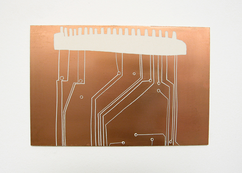
Figure 1 Thessia Machado, Connectors. Photo © Thessia Machado, used by permission.
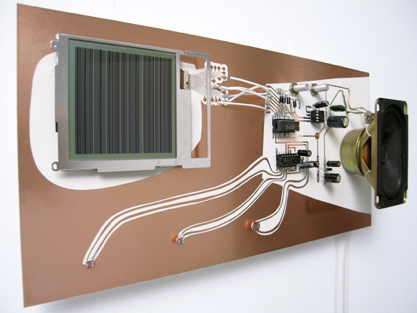
Figure 2 Thessia Machado, Translux. Photo © Thessia Machado, used by permission.
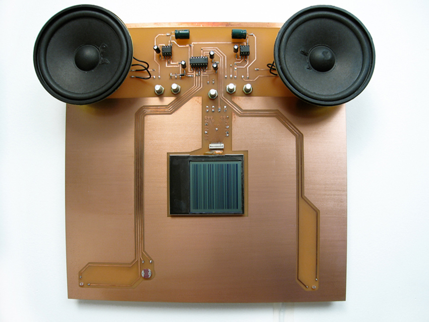
Figure 3 Thessia Machado, Interference. Photo © Thessia Machado, used by permission.
Over the years John Richard’s Dirty Electronics project has centered on both designing instruments and developing an ensemble practice whose performers are drawn from workshops on building small synthesizers. It is a highly collaborative activity. One recent work, Polytik (figure 4), was designed by John Richards and Jack Featherstone in collaboration with other artists and engineers. Polytik is comprised of four modules, each of a different shape and color, and displaying a creative layout of components on the board. They resemble elegant fabric patterns, or a beautifully presented dish. Functionality is a priority, but so is the way design mediates or informs the decisions of the performer. Other projects Dirty Electronics projects include a collaboration with Chris Carter and a project based on William Morris’ designs.
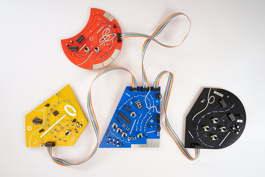
Figure 4 John Richards and Jack Featherstone, Polytik. Photo © John Richards and Jack Featherstone, used by permission.
Addie Wagenknecht’s piece Data and Dragons: Cloud Farming (figure 5) is a good example of how the design of PCBs can reflect the ideas that are being explored in the creative work incorporating the instrument. Custom-designed boards are displayed in a form that resembles a 3d modeled cloud, and the resulting artwork addresses the perplexing nature of the internet cloud and the infrastructure that supports it. Wagenknecht is the director of Deep Lab, a cyberfeminist collaborative group focused on critically engaging digital culture, including matters of surveillance, hacking, anonymity, race and more.
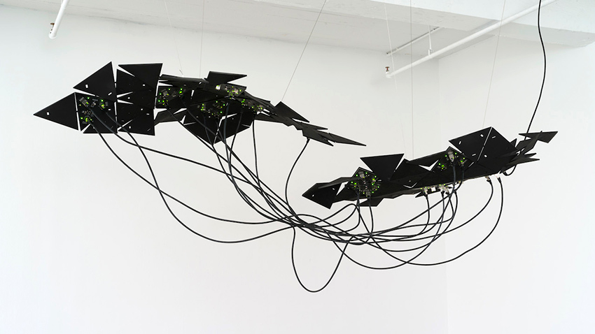
Figure 5 Addie Wagenknecht, Data and Dragons: Cloud Farming. Photo © Addie Wagenecht, used by permission.
Martin Howse is an artist based in London and Berlin whose work unfolds in the region of scientific research and technological experimentation. Howse calls his practice “micro-research”, for which he has developed multiple instruments for which the creative aspect of PCB design is essential. Characteristic projects include The Dark Interpreter (figure 6), Wormed Voice and the earthboot USB device (figure 7). These instruments reveal the somewhat esoteric domain that serves as a substrate for Howse’s practice.
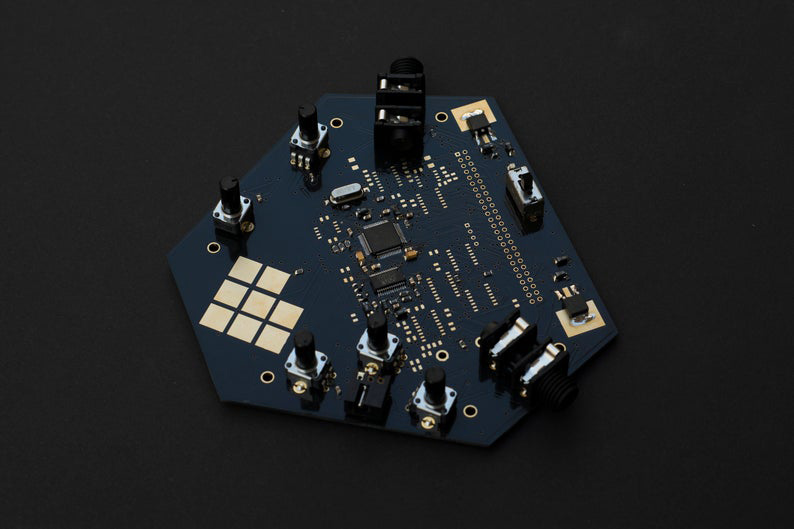
Figure 6 Martin Howse, The Dark Intepreter. Photo © Martin Howse, used by permission.
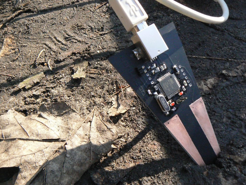
Figure 7 Martin Howse, earthboot. Photo © Martin Howse, used by permission.
Figure 6 Martin Howse, The Dark Intepreter. Photo © Martin Howse, used by permission.
Figure 7 Martin Howse, earthboot. Photo © Martin Howse, used by permission.
How many times we have heard that a circuit board looks like a city? In Tube Map Radio (figure 8) Yuri Suzuki’s use Harry Beck’s London Tube map as the layout for a PCB, evoking Pynchon’s character Oedipa’s comparison the insides of a radio to the cityscape of San Francisco. Tube Map Radio takes two complex systems and mirrors them in a way that might clarify understanding of both.
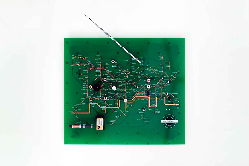
Figure 8a Yuri Suzuki, Tube Map Radio. Photo © Yuri Suzuki, used by permission.
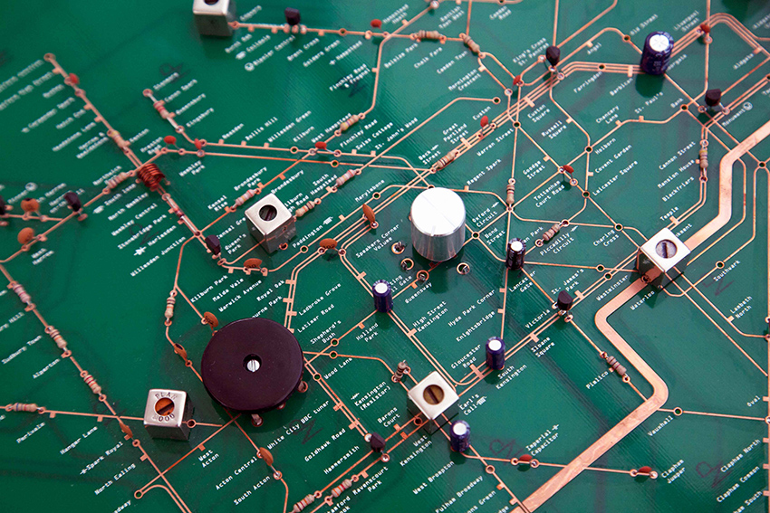
Figure 8b Yuri Suzuki, Tube Map Radio. Photo © Yuri Suzuki, used by permission.
Figure 8 Yuri Suzuki, Tube Map Radio. Photo © Yuri Suzuki, used by permission.
Folktek, established in 2007, has designed some popular instruments such as Mescaline (figure 9). In their earlier work one can find pieces such as the Electric Hands (figure 10), in which two hands are etched into the playing surface of the instrument (evoking the legendary Cracklebox – see sidebar in chapter 12), and the Time Machine (figure 11) whose patchable surface features pads to which connections are made magnetically.
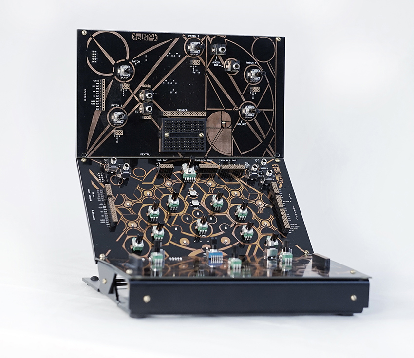
Figure 9 Folktek, Mescaline. Photo © Folktek, used by permission.
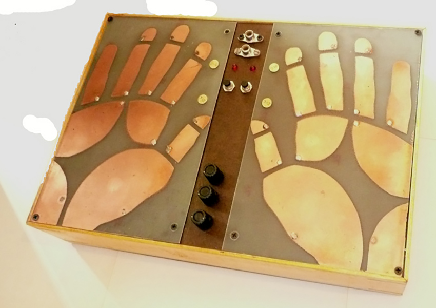
Figure 10 Foltek, Electric Hands
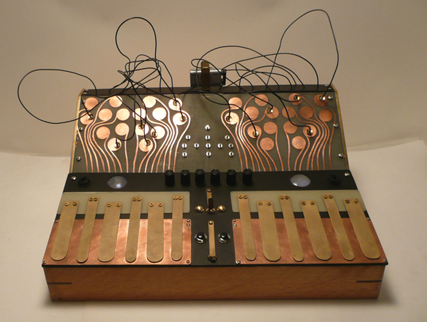
Figure 11 Folktek, Time Machine. Photo © Folktek, used by permission.
In the Netherlands Gijs Gieskes has designed some exotic boards, including one based on Futurama’s Hypnotoad. Gieskes works mostly with circuit-bending, producing objects for both video and sound, but he is well-known as a chiptune artist. Notable is his series of boards named Dirty Express (figure 12), whose parts are arranged in a disturbingly arbitrary fashion, with traces, holes and outlines overlapping, and parts connected to nothing.
In the Netherlands Gijs Gieskes has designed some exotic boards, including one based on Futurama’s Hypnotoad. Gieskes works mostly with circuit-bending, producing objects for both video and sound, but he is well-known as a chiptune artist. Notable is his series of boards named Dirty Express (figure 12), whose parts are arranged in a disturbingly arbitrary fashion, with traces, holes and outlines overlapping, and parts connected to nothing.
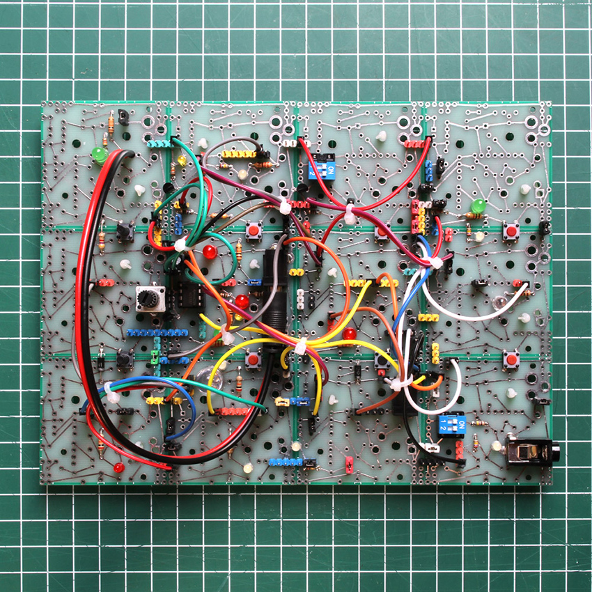
Figure 12a Gijs Gieskes, Dirty Express. Photo © Gijs Gieskes, used by permission.
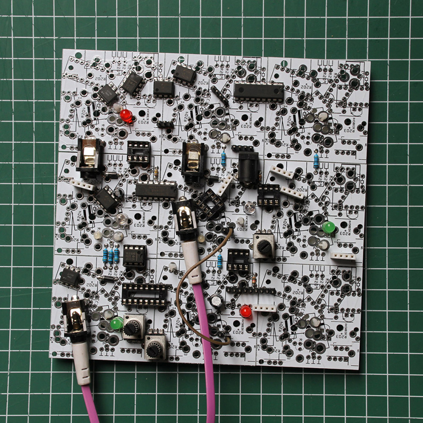
Figure 12b Gijs Gieskes, Dirty Express. Photo © Gijs Gieskes, used by permission.
Circuit Bending
Nicolas Collins
Traditionally, making functional electronic objects has necessitated a fair grasp of theory and a pretty clear idea of what you wanted to make before you picked up your soldering iron. David Tudor, Gordon Mumma, Composers Inside Electronics, and other musical designers began chipping away at these assumptions in the 1960s and 1970s. Being self-taught, they had only piecemeal knowledge of electronic theory and were less concerned about doing things “properly” than about making something that sounded cool. Immersed in a musical ethos that valued chance, they were highly receptive to accidental discoveries—in the pursuit of the “score within the circuit,” they relished wandering down side paths, rather than race-walking toward a predetermined goal.
Then in the mid-1990s Reed Ghazala pushed serendipity back to the fore of electronic practice with his fervent advocacy of what he dubbed “circuit bending.”1 Like Waisvisz (see “The Cracklebox,” chapter 12), as an adolescent in the late 1960s Ghazala encountered the sounds of accidental circuit interaction: an open amplifier left in his desk drawer shorted against some metal and began whistling. After some experimentation, Ghazala added switches so he could control the shorting, and Circuit Bending was born. He developed a series of techniques for modifying found circuitry—especially electronic toys, whose sonic sophistication grew in direct response to the boom of semiconductor technology in the 1980s—without the benefit of the manufacturer’s schematics, or any engineering knowledge whatsoever. In 1992 he began publishing instructive articles in Experimental Musical Instruments (an influential journal for instrument builders) and acquired a cult following2. In 1997 he launched his Web site and today a cursory Web search will reveal news groups, festivals, and workshops for circuit bending all over the world.
Circuit bending is freestyle sound design with a postmodern twang—the perfect escape for artists bored by the powerful, but often stultifyingly rational, software tools that increasingly dominate music production, yet still hooked on the digitally inspired cut-and-paste aesthetic of scavenging, sampling, and reworking found materials. With its defiantly antitheoretical stance and emphasis on modifying cheap consumer technology, bending has a natural egalitarian appeal (as well as some odd orthodoxies: looking at my instruments as I was setting up a demonstration at the “Bent 2004” Festival at The Tank Gallery in New York City, an audience member inquired, “Are they bent or hacked?” When I looked baffled he elaborated: “‘Bent’ means you have no idea what you are doing when you open up the circuit; ‘hacked’ means you have some idea”). But bending’s try-anything extreme experimentalism can produce wonderful results never anticipated by the original designers of the device being bent.
Some benders specialize in particular adaptations: German musician Joke Nies has made a specialty of hacking an early digital instrument called the “Omnichord” (see figure 1); my ex-student Jon Satrom has based his VJ career on a specific V-Tech children’s toy (see his video in the “Visual Hacking” section of the Gallery on this website). Texas Instrument’s “Speak and Spell” has been a favorite from the day it was introduced in 1978, long before the term “bending” came into use. Web sites abound with detailed instructions for specific cuts and jumpers on the boards of particular toys.
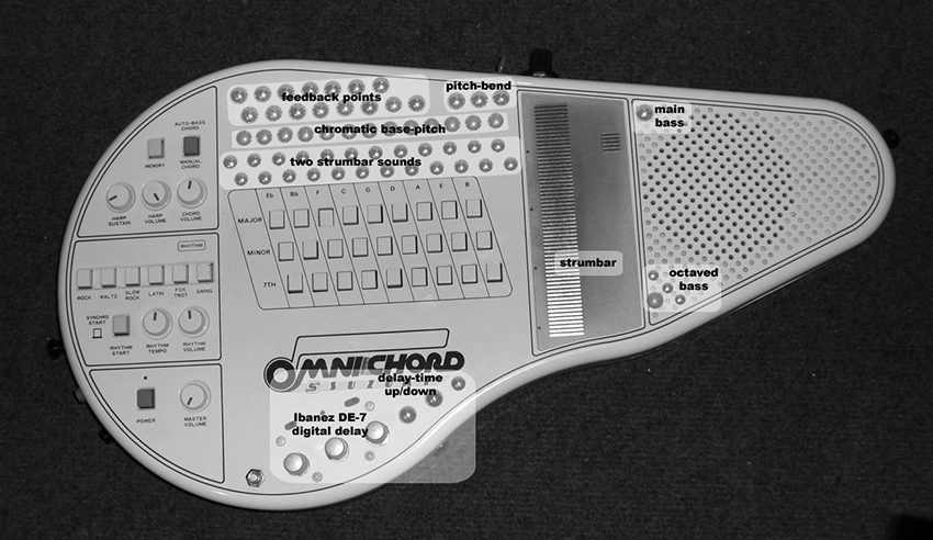
Figure 1 Bent Omnichord, Joker Nies. Photo © Joker Nies, used by permission.
Phil Archer (UK) and John Bowers (UK) are representative of the recent generation of hackers, who effortlessly combine bending with Tudor-era contact mike technology and sophisticated computer programming. Archer did the “classic” bend to his Yamaha PSS-380 keyboard: exposing the circuit-board, placing the inverted instrument on the performer’s lap, and making arbitrary connections between components on the board with a stripped piece of wire (see figure 11 and his audio track in the “Circuit Bending” section of the Gallery on this website). “These connections,” he writes, “induce tones, bursts of noise and corrupted ‘auto-accompaniment’ sequences from the device which are unpredictable in their details but generally ‘steerable’ overall with practice. The precision and control afforded by the standard keyboard interface is eschewed in favour of direct contact with the circuit, and the performer is continually forced to rethink and re-evaluate their relationship with the instrument in light of the sonic results.”3 Most of his other instruments have a Frankenstein quality: a midget Hawaiian guitar whose single string is played by the sled mechanism from a CD player (see figure 2); a set of small percussion instruments whacked and scraped by motors from a dot matrix printer; a music box mechanism activating bent electronic keyboards.

Figure 2 “CD Player Slide Guitar,” Phil Archer. Photo © Phil Archer, used by permission.
John Bowers, in an ongoing struggle against his training as a computer scientist, “reinvented” what he has dubbed the “Victorian Synthesizer” (see chapter 3 and audio track in the “Laying of Hands” section of the Gallery on this website): it produces sounds with speakers animated directly by batteries, bereft of intervening electronic circuitry. Corroded metal, mercury-filled tilt-switches, and a handful of screws and washers complete instruments that could indeed have been built in the nineteenth century. His other “Infra-Instruments” combine similar electro-mechanical technology (mixing bowls filled with motors, magnets, contact mikes and guitar pickups (see figure 3); microphones embedded in a plank of wood; strings, stones, and guitar pickups strewn across a table with computers and rock effect boxes)4.
Notable younger Benders include Knut Aufermann (Germany/UK), Xentos “Fray” Bentos (UK), David Novack (USA), Vic Rawlings (USA), Sarah Washington (UK), Chris Weaver (UK) and Dan Wilson (UK)5. Britain’s particularly vibrant bending scene (including an “all bending ensemble,” P. Sing Cho— see their audio track in the “Doing It Together” section of the Gallery on this website) has roots in the prevalence of toys as affordable, alternative noisemakers among improvisers in the 1970s—most significantly Steve Beresford. As Sarah Washington says, echoing Tudor from four decades earlier, “I am an improvising musician…the choice of sounds is down to the circuit – whatever it comes up with is fine with me” (see figure 4)6.

Figure 3 “Mixing Bowl,” John Bowers. Photo © John Bowers, used by permission.
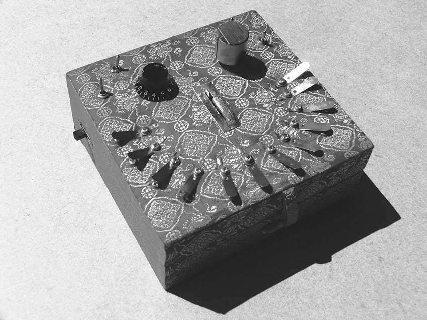
Figure 4 “Mao Tai,” Sarah Washington. Photo © Sarah Washington, used by permission.
1 Reed Ghazala: http://www.anti-theory.com. Reed Ghazala, Circuit Bending: Build Your Own Alien Instruments. New York: Wiley Publications, USA, 2005.
2 Experimental Musical Instruments: http://www.windworld.com/
3 The Phil Archer quotation is from personal correspondence, 2003.
4 Bowers, J., and Archer, P. “Not Hyper, Not Meta, Not Cyber but Infra-Instruments.” In Proceedings of NIME‚05 (New Interfaces for Musical Expression), May 26–28, 2005, Vancouver, BC, Canada. Downloadable from http://hct.ece.ubc.ca/nime/2005.
5 Rawlings, Vic. “The Boss GE-7 E.Q. and Flexible Speaker Array as Tonal Filters”. Leonardo Music Journal Vol. 17 (2007). Pp. 37-38.
6 The Sarah Washington quotation is from personal correspondence, 2003. Leonardo Music Journal Vol. 17 (2007), My Favorite Things – The Joy of the Gizmo, features articles and artist’s statements by many Circuit Benders, as well as a CD, curated by Sarah Washington, with 17 tracks by various artists.
Visual Music
Nicolas Collins
Electronics have pervaded and altered our visual world as profoundly as our sonic one and, furthermore, allowed us to link the two in peculiar, causal ways. In his 1965 work “Magnet TV,” Nam June Paik sat a large magnet on top of a television set to distort its image; although technically rather crude, this piece presaged the considerably more “sophisticated” electronic image processing that would come to typify much subsequent video art1. “Magnet TV” established a hacker precedent that would remain a consistent presence in Paik’s work, as well as in that of many multi-media artists who followed him.
Before lightning-fast personal computers with massive amounts of memory made digital video processing as commonplace as word processing, Paik-like hacks were the only affordable way to manipulate visual images in real time, or to create linkages between video and audio. Video feedback was as common a tool for early video artists as audio feedback was for electronic music composers: Bill Viola (USA) made extensive use of it in the 1970s; more recently Billy Roisz (Austria) has VJ-ed with video feedback, modifying it through simple video mixers and keyers, and splitting the video signal to feed the PA as well, so that the bursts and jitter of the images are heard in parallel as glitches and hums (see figure 1).

Figure 1 Four stills from a video feedback performance by Billy Roisz. Photo © Billy Roisz, used by permission.
Cloud Music is a video/music installation developed by David Behrman, Bob Diamond, and Robert Watts between 1974 and 19792. In the earliest version, a camera was pointed at the sky and connected to a video monitor. A number of photoresistors were affixed to the screen. The light values of the passing clouds changed the resistance of the photoresistors, and, in turn, affected the sound score. Yasunao Tone (JP/USA) used a similar approach in his Molecular Music (1982–85): photoresistors are taped to the surface of a screen onto which a film is projected; each photoresistor controls the pitch of an oscillator (similar to those described in chapter 18), and the resulting sound mass responds directly to the change in projected images (see figure 2). Today Tone is best known as the “grandfather of glitch”: he began “wounding CDs” in 1985 by applying Scotch Tape punctured by pinholes to the underside of the disks; the resulting frenetic digital error-fest was the first documented music made with intentionally damaged CDs (see his audio track in the “Circuit Bending” section of the Gallery on this website)3. The intertwining of light and sound are central to Tone’s work: the deflection of lasers through pinholes is a miniaturized, but nonetheless logical, extension of film interrupting the projector’s light before it strikes the photoresistors. Similar experiments in controlling circuits through photoresistors reacting to projected light have been done more recently by Jeffrey Byron and Jay Trautman, Joe Grimm, Kyle Evans, and Infrason (see their videos in the “Visual Hacking” section of the Gallery on this website).
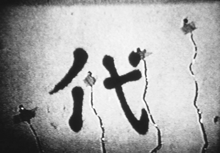
Figure 2a Two stills from Molecular Music, Yasunao Tone. Photo © Yasinao Tone, used by permission.

Figure 2b
In 1969, long before planetarium laser shows, Lowell Cross (USA), a frequent collaborator of John Cage and David Tudor, created the first sound-modulated laser projections for his work VIDEO/ LASER II: the laser (enormous at the time—see figure 3) was reflected off mirrors mounted on transducers called galvanometers, which vibrated in response to sound input to create curving Lissajous patterns on the wall. (Lowell Cross also built a beautiful photoresistor-based matrix mixer embedded in a chessboard for the famous 1968 John Cage/Marcel Duchamp chess-playing performance, “Reunion”)4.
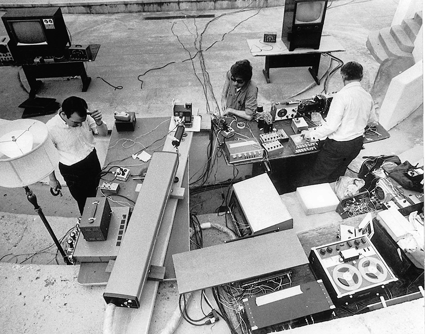
Figure 3a Lowell Cross (left), Eugene Turitz (center) and David Tudor (right) setting up for the first laser light show to use x-y scanning, Mills College, Oakland, CA, May 9, 1969. Photo © Baron Wollman for the Tape Music Center, used by permission of Lowell Cross.
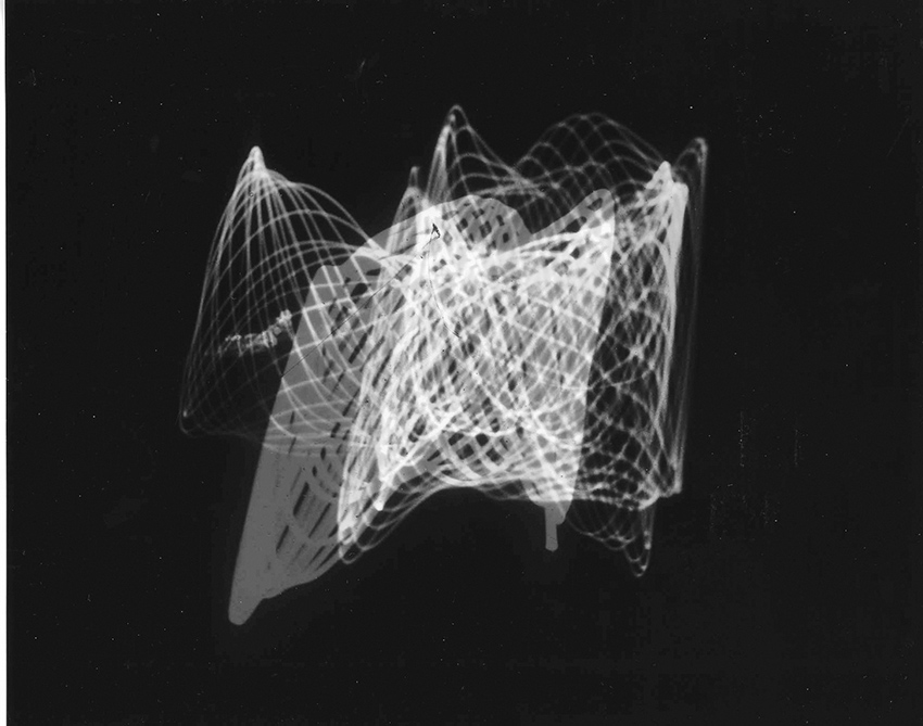
Figure 3b Laser-projected image from VIDEO/LASER II, December 1969, Lowell Cross. Photo © Lowell Cross, used by permission.
In 1999, when Stephen Vitiello had an artist’s studio on the ninety-first floor of the World Trade Center in New York City, he and Bob Bielecki (see “The Luthiers”) hooked up a photoresistor to a battery (as shown in the “Video Music” chapter in the Circuit Bending section of this website), placed it on the eyepiece of a telescope, aimed it down at New Jersey, and sat together listening to the flashing lights on a police car across the Hudson. Vitiello has made a beautiful series of recordings using this “audio-telescope” (see his audio track in “Visual Hacking”). Norbert Möslang and Andy Guhl of Voice Crack (see “Composing Inside Electronics,” chapter 15), have used similar circuits to extract surprisingly rich rhythmic and harmonic textures from the light patterns of bicycle flashers and LEDs on toys (see their audio and video tracks in “Visual Hacking”).
Computers finally caught up with video, but visual hacking hasn’t stopped. The disparity between the $100-portable LCD TV and the $5,000-video projector offended the sensibility of the Dutch electronic performance trio BMBCon (Justin Bennett, Wikke ‘t Hooft , and Roelf Toxopeus), so in the mid-1990s they took the screens from cheap TVs (which have the same dimensions as 35mm slides) and dropped them into old slide projectors from the flea market—voilá: the home-made, low-budget video projector (see figure 4 and their video in “Visual Hacking”). In my installation Daguerreotypes (2006) high intensity LEDs shine through LCDs from toys and games, projecting a sort of miniature wayang shadow play onto the walls of a gallery (figure 6 and video in “Visual Hacking”).
Figure 4 Homemade LCD projector, BMB Con. Photo © BMBCon, used by permission.
Figure 5 Detail from Daguerreotypes installation with LCD screen and LEDs, Nicolas Collins.
Jon Satrom (USA) has built his VJ career on transforming a child’s “video paint box” into an instrument he calls the “Vitch” (see figure 6 and his video in “Visual Hacking”). By inserting Circuit Bending-style jumpers between various points on the circuit board, Satrom is able disrupt the toy’s functions to produce a remarkable range of fragmented, frozen, superimposed, and digitally warped images (essentially a video equivalent of the keyboard malfunctions described by Phil Archer in “Circuit Bending”). Similar video circuits have been bent by Jordan Bartee (USA), J. D. Kramer (USA), Phil Stearns (USA), and the trio of Abbot, Archer and Tombs (UK) – see their videos in “Visual Hacking”. Tali Hinkis and Kyle Lapidus of the video hacking duo LoVid (USA) have created wonderful homemade video synthesizers, occasionally built into soft sculpture and wearables. Their “Kiss Blink Sync Vessel” is a collection of modules, embedded in tabletops, that can be patched together to synthesize both video and sound (see figure 7 and their video in “Visual Hacking”).
Figure 6a “The Vitch”, John Satrom, left. Video image from performance, right. Photos © Jon Satrom, used by permission.
Figure 6b “The Vitch”, John Satrom, left. Video image from performance, right. Photos © Jon Satrom, used by permission.

Figure 7 “Kiss Blink Sync Vessel”, LoVid. Photo © LoVid, used by permission.
And in a pseudo-Victorian twist that would make John Bowers proud, Dutch artists Arthur Elsenaar and Remko Scha attach electrodes to Elsenaar’s face and electrically stimulate the muscles of expression to provide an “emotional display” for their computer (see figure 8 and their video in “Visual Hacking”)5.
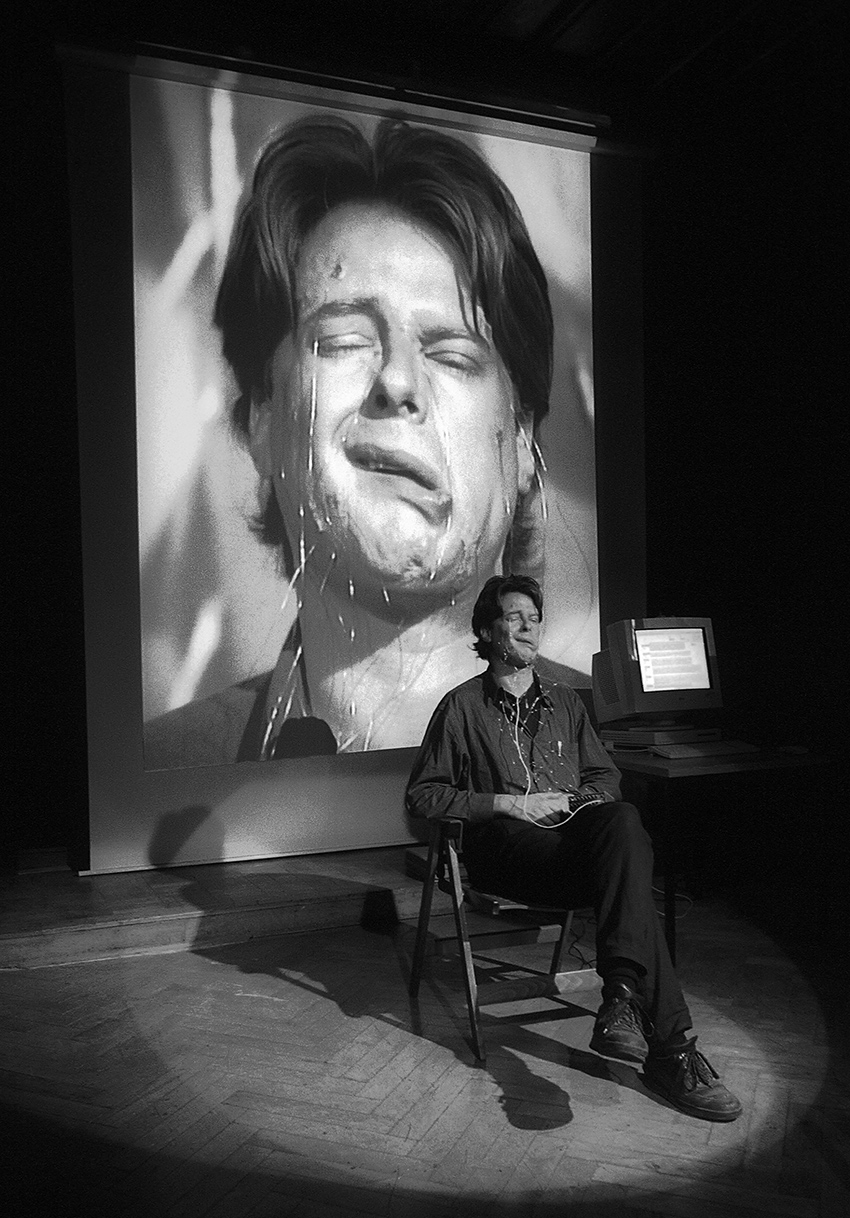
Figure 8 Portrait of Arthur Elsenaar’s face displaying an electrically-induced artificial facial expression. Photo by Josephine Jasperse, used by permission of Arthur Elsenaar and Remko Scha. © Josephine Jasperse.
1 http://www.nydigitalsalon.org/10/artwork.php?artwork=27
2 http://www.vasulka.org/Kitchen/PDF_Eigenwelt/pdf/152-154.pdf
3 Yasunao Tone (Asphodel Ltd., Asphodel 2011), 2003. Solo for Wounded CD (Tzadik, TZ-7212), 1997.
4 Lowell Cross, “‘Reunion’: John Cage, Marcel Duchamp, Electronic Music and Chess.” Leonardo Music Journal, Vol. 9 (1999). Pp. 35-42.
5 Arthur Elsenaar and Remko Scha, “Electric Body Manipulation as Performance Art: A Historical Perspective.” Leonardo Music Journal, Vol. 12 (2002). Pp. 17-28.
The Future Was Then
A View From 2009
Nicolas Collins
In 2009, the original text of Handmade Electronic Music was expanded and updated. In addition to adding further projects for readers to execute, the new book included an overview of the hardware hacking music and sound art scene as it seemed configured at that time. Circuit bending was the dominant trend, and the power of hacking as a social glue and global tool of resistance and capacitance was only beginning to be felt. For the third edition of the book, I have invited scholars, artists, musicians and activists from around the world to bring us up to date on the cultural impact and creations of a broad range of contemporary scenes. In the interest of history, however, I am also reprinting that earlier essay from 2009, lightly edited for flow and fact, but in content a snapshot of that moment.
In the second edition of Handmade Electronic Music (HEM) I have attempted to correct errors and oversights, to satisfy readers requests for more projects, and to respond to developments in the seven years since I started this project in 2002. At that time, younger artists working with technology were largely focused on computers and the multitude of newly available programs; the contrarian remainder was under thrall to circuit bending. Accordingly, I took basic bending as the center of my workshops and of the resulting text, extending the bending methodology backwards and forwards, so to speak. We started with alternate ways of listening: making and using contact mikes, coils, tape heads, electret elements and other alternative microphones; playing radio circuit boards with naked flesh as a way to sensitize our hands to circuitry. Then, when it seemed that the students, like children at Christmas, would burst if they couldn’t open up their toys RIGHT NOW, we moved on to hacking clocks, shorting circuits, and indulging in the other heady, pseudo-random practices that fell under the rubric of Circuit Bending. When boredom set in, or students tired of subsidizing toy stores and Goodwill shops, we took up our first oscillator. From there our silicon future unfolded, and as the years passed I was pressed to keep adding to the collection of circuits, as reflected in the expanded content of the second edition.
Subsequent to HEM’s initial publication in 2006 I came into contact with a vast sea of benders and hackers. Every few weeks I received a request for assistance on a recalcitrant project, or someone would send me a link to a YouTube clip or a web site demonstrating some cool thing whose connection to my book they felt compelled to point out. My correspondents all shared a “whatever it takes” attitude toward technology. This wave of hackers was not fixated on any particular technology or methodology, instead they moved with grace from hardware to software, from soldering to sawing, from audio to video, from stage to gallery, from adaptive re-use to spontaneous creation, from happenstance to intent, from idiocy to genius. If there was any unifying trait, it was the desire to disrupt technology’s seemingly perfect inviability.
As I wrote in the Introduction to the first edition of this book, the sticker advising “no user serviceable parts inside”—whether affixed to a toy, a TV, a computer, a motor, or even a single integrated circuit—should be taken as a challenge. And for that challenge we must all, hacker and non-hacker alike, be grateful: today’s “breakers” become tomorrow’s “makers1 .” Behind a goofy YouTube video might lurk the next Steve Jobs, Limor Fried or Sergey Brin, or alternatively the next John Cage, Daphne Oram or Nam June Paik. If technology’s evolution, like that of snails or finches, follows a pattern of punctured equilibrium, hackers are holding the pointed sticks. And while we wait for the NEXT BIG THING, we can enjoy the delicious din of all the now little things.
Another addition to second edition was a DVD gallery of 87 now things, each squeezed into a 60-second package (my daughter, then nine years old, maintained that no video should ever be longer than one minute). Taken together, these videos [now available on the website for the third edition] provide an overview of diverse activity of the early 2000s. Though it is hard to categorize in a meaningful way, seven threads seem to weave through the collection: Beyond Bending (the state of circuit bending); Feedback (the guitarist’s friend grows up); Off The Grid (abandoning batteries); I’m With The Band (making music together); Sound and Vision (an art school style); Mechanics (getting very physical); and Swashbuckler (some truly virtuosic iconoclasts).
Beyond Bending
Circuit bending has changed since Reed Ghazala coined the term.in the 1990s. One factor has been the shift in electronic toy production toward greater integration of functions in a single chip. At the end of the last century, control of a toy’s various functions (making sound, blinking lights, reading switches, defining the clock speed, etc.) was typically distributed among several different integrated circuits and associated components, and benders delighted in messing around with the myriad connections between them. In the 21st century integration has reached the point that everything is controlled by a single malevolent-looking black blob. There are no exposed connections to rearrange, and with more and more on-chip clocks, not dependent on an external resistors, even the most basic changing-the-clock-speed-bend is impossible. With new toys defiantly bend-resistant, today’s bender is condemned to wander the aisles of thrift shops, garage sales and eBay continually confronting the same stock of vintage toys.
The frustration is compounded by ennui. Bending celebrates the first rule of hacking— ignorance is bliss. It shuns theory (Ghazala’a web site is aptly named www.anti-theory.com) and encourages instead the sharing of empirical observation: insert a jumper between these points and this will happen, don’t worry about why. In contrast to the laborious analytical work that had previously characterized electronic engineering even in hobbyist and musical circles, this philosophy is tremendously liberating for the first-time hacker. But after the thrill of “how” wears off, some of us ask “why?” Accordingly, while an artist may gain access to circuitry through classic bending activities, she may move on to diversify her electronic portfolio: interconnecting toys, combining handmade circuitry with bent toys, hacking other found technology (effect pedals, video circuits, mechanical devices), writing software, etc.
Rather than bending toys, for example, Neal Spowage (UK) built his Electro Magnetic Wands, a responsive performance instrument, from metal detectors and security wands (fig. 1). Kaspar König’s (Netherlands) Musguitear uses hacked mosquito killers, and Chris Powers (USA) has modified guitar effect pedals, bringing touch-sensitive contact points from the circuit board out to a set of electrodes he plays with his bare toes (figure 2). Charles McGhee Hassrick (USA) takes a strategically ecological approach, creating audio-visual installations using only the discarded trash of the museums, galleries and other venues where he exhibits.
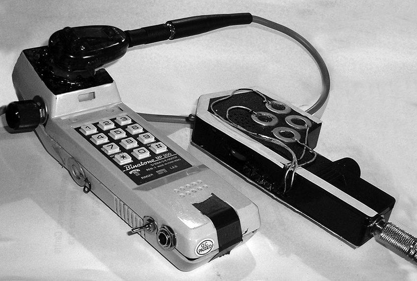
Figure 1 Neal Spowage, Electro Magnetic Wands. Photo © Neal Spowage, used by permission.
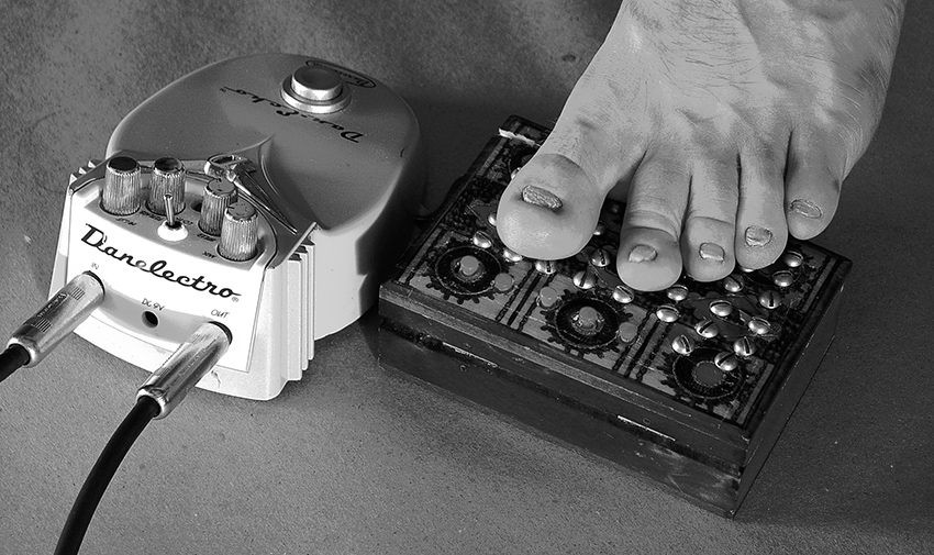
Figure 2 Chris Powers: hacked guitar effect pedal with electrodes for toes.
Many artists extend their bends with computers or scratch-built circuitry. For his After Math, Chester Udell (USA) hacked a TI Speak & Math (one of the most popular toys for bending) so that it could be manipulated by flight simulator controllers through a computer and MIDI (fig, 3). Ian Baxter (UK) fabricated external body contacts to control a voice changer toy for a performance instrument he calls the Masher. Haco (Japan) modified an electric organ kit so it could be controlled by electrodes for body contact and a combination of pencil lines on paper.
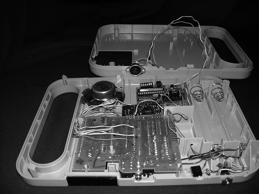
Figure 3 Chester Udell, After Math Hacked TI Speak & Math showing MIDI interface board. Photo © Chester Udell, used by permission.
Several musicians have “bent” electric guitars and other acoustic instruments by embedding circuitry. Jeffrey Byron (USA) installed bent toys in his electric guitar. Zach Lewis (USA) replaced the neck pickup in his Fender Toronado with photoresistor-controlled oscillators, that are “played” by the shadows cast by the pick-wielding hand (fig. 3). Peter Blasser’s (USA) Radiothizer resembles a koto but contains Theremin-esque circuits that transform the sound of the plucked strings in response to movement of arms in the spatial field of the instrument. Ben Neill (USA) added switches and pots to his trumpet in order to control a computer music system via MIDI.
Figure 4a Zach Lewis, Oscillators embedded in electric guitar. Photo © Zach Lewis, used by permission.
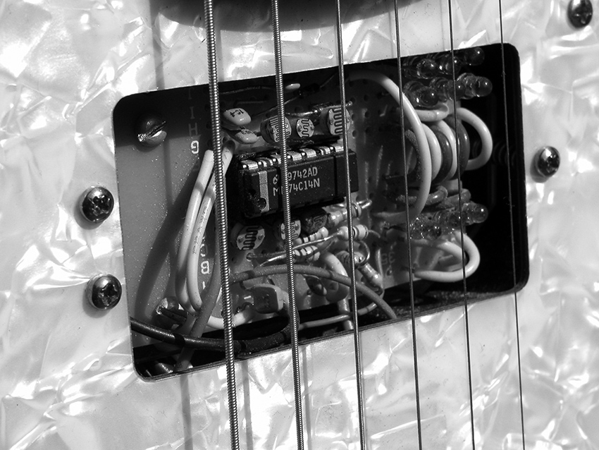
Figure 4b
Feedback
Interest in live performance and interactivity led many musicians and artists to experiment with one of the most basic electronic sound resources, feedback. For her Speaker Synth, Lesley Flanigan (USA) placed contact mikes inside the cones of five open speakers to control their feedback (fig. 5). Minoru Sato (Japan) embeds microphones and small speakers at the opposite ends of glass tubes and adjusts the gain to create a feedback organ. For their performance work Crude Awakening, Chris Black and Chris White (New Zealand) use an array of speakers and contact mikes to resonate common objects (metal pans, grills, coils of wire, etc) that are physically twisted to affect their feedback pitch. Frederick Brummer (Canada) filters feedback through drum heads, and Gert-Jan Prins (Netherlands) continues to do amazing things with radio-frequency feedback between homemade transmitters and receivers.
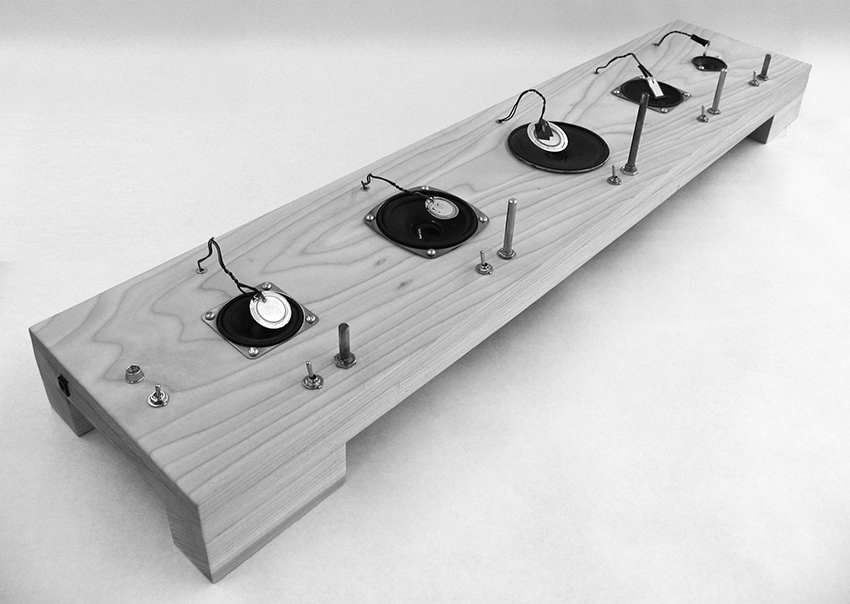
Figure 5 Lesley Flanigan, Speaker Synth (2007). Photo © Lesley Flanigan, used by permission.
Matrix feedback amongst multiple circuits, as pioneered by David Tudor, came back into popularity in the 1990s through the work of Toshimaru Nakamura (Japan) and other advocates of “no-input mixing,” in which mixers and arrays of circuits are transformed into oscillators by patching cables from outputs to inputs. Vic Rawlings (USA) configures naked circuits and numerous small speakers in complex feedback loops, which he manipulates by rubbing wire brushes across the circuit boards.
Off The Grid
Well before the first Teslas rolled off the assembly line hackers began experimenting with alternate sources of energy. Both Daniel Schorno (Switzerland/Netherlands) (fig, 6) and Fred Lonberg-Holm (USA) harnessed solar power for performance instruments and installation projects. The Music Boxes of Phil Archer (UK; fig. 7) and the Synthinetic of Ithai Benjamin and Alex Abreu (USA; fig 8) incorporated hand-cranked generators as power sources whose instability becomes a defining characteristic of the circuit’s performance. Emir Bijukic (Italy) listened to various points on the circuit board of a solar-powered calculator while varying the light level and brushing his fingers across the exposed traces (fig. 9). Lorin Edwin Parker’s steam-driven synthesizer is described in chapter 4 (see figure 4.2). And in a tour de force of engineering, M. R. Duffey (USA) designed Solar Thermal Automata, based on plans and descriptions dating back to classical Greece and Rome; these utilize heat engines to generate organ-like sound directly from solar heat without the need for any electronic circuitry.
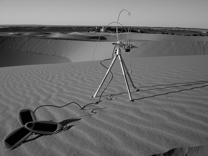
Figure 6 Daniel Schorno, Desert Scorpio (2007). Installation on solar chargeable battery in Erg Chebbi Desert, Morocco. Photo by Susanna Bachmann, © Daniel Schorno, used by permission.
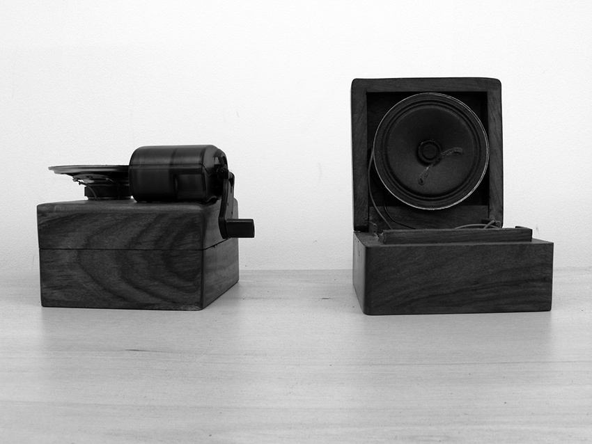
Figure 7 Phil Archer, Music Boxes with hand-cranked dynamo power. Photo © Phil Archer, used by permission.
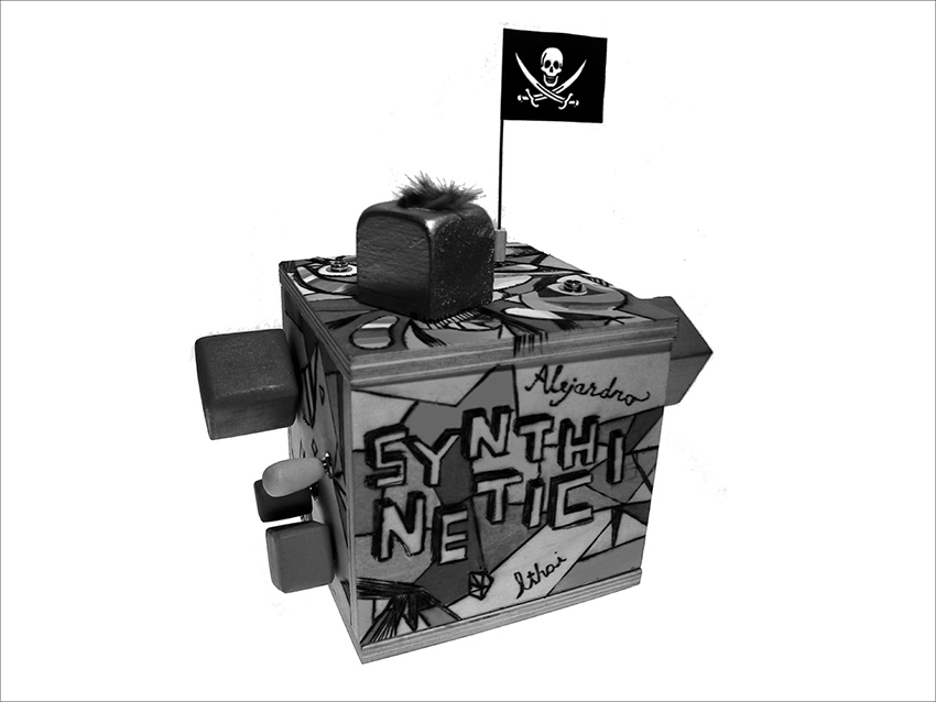
Figure 8 Ithai Benjamin and Alex Abreu, Synthinetic using motor as a generator. Photo © Ithai Benjamin and Alejandro Abreu, used by permission.
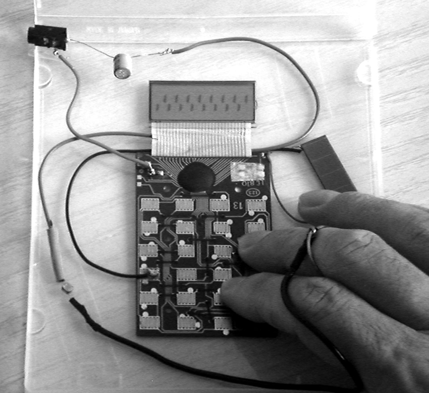
Figure 9 Emir Bijukic, Solar powered calculator touch synthesizer. Photo © Emir Bijukic, used by permission.
I’m With The Band
Among the many bands formed by benders and hackers is NotTheSameColor (Billy Roisz and Dieter Kovacic, Austria) which combines live manipulation of sound and video (fig. 10). Japan’s (e)-bombers are a bending big-band: six guys with bent toys and homemade circuitry, each wearing his own PVC-encased speaker system. Oscillatorial Binnage (Fari Bradley, Toby Clarkson, Chris Weaver and Dan Wilson) and Owl Project (Simon Blackmore, Antony Hall and Steven Symons) and P. Sing Cho (Knut Aufermann, Moshi Honen, Sarah Washington, Chris Weaver and Dan Wilson) are all electronic ensembles active in the UK. Other British combos include Grace and Delete (James Dunn and Chris Cundy), who mix hacked electronics (including bent keyboards and, appropriately enough, a tinnitus analyzer) with bass clarinet; and the Bent Radio Orchestra (Stewart Collinson and Duncan Chapman), which—building on the grand tradition of the Scratch Orchestra and Portsmouth Sinfonia—invites the public to bring, open, and lay hands upon radios (as demonstrated in chapter 12) for mass performances. The rgb.toysband, formed after a workshop I gave in Brussels in 2005, took electronic music into the streets, train stations and other public spaces; its members published a manifesto of sorts encouraging others to create satellites of the original group (similar hacking bands have sprung up out of workshops in Cuneo and Padova, Italy, and Zurich, Switzerland.)
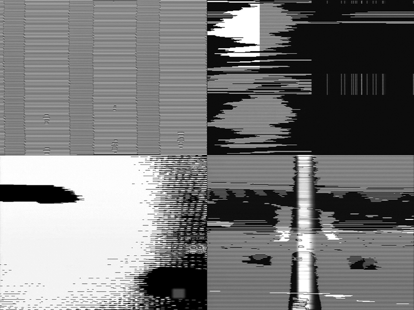
Figure 10 Four stills from video feedback performance by Billy Roisz. Photo © Billy Roisz, used by permission.
Several ensembles make a point of building circuits in front of their audience, rather than bringing completed instruments to the stage. The Swiss Mechatronic Art Society gives regular performances that feature live soldering—once with all members of the group linked to a central master clock powered by dripping water. (This group also conducts workshops and publishes circuit designs on-line). The members of New York-based Loud Objects (Tristan Perich, Kunal Gupta, Katie Shima) program microcontroller chips to produce and process sound, then solder them together on top an overhead projector in front of the audience, who can watch the connections proliferate on the big screen (fig. 11). My own workshops usually end with a public event in which the audience wanders among the busy hackers as they assemble and test their last contact mikes, bent toys and noisy circuits—a sort of factory floor concert. In my recent piece Salvage–Guiyu Blues, seven players use test probes to make a dozen connections between a simple circuit of my design and contact points on a defunct found circuit board (which might come from a computer, cell phone, fax machine, mixer, etc.), reanimating the dead circuit and transforming it into a complex oscillator (fig. 12). At the NIME Festival in Brooklyn in June 2007 I battled my young British dopplegänger, Nick Collins, for the Nic(k) Collins Cup (the cup itself was commissioned from British potter Nic Collins) in a concert that pitted live SuperCollider programming by Nick against live circuit building by Nic.
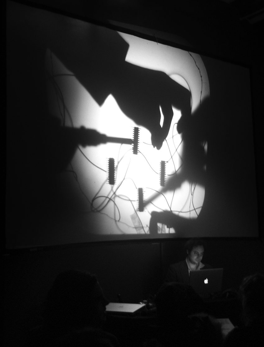
Figure 11 Live soldering performance by Loud Objects, showing overhead projection of work surface. Photo by astrobelle, © Isabelle Sigal, used by permission of Loud Objects.
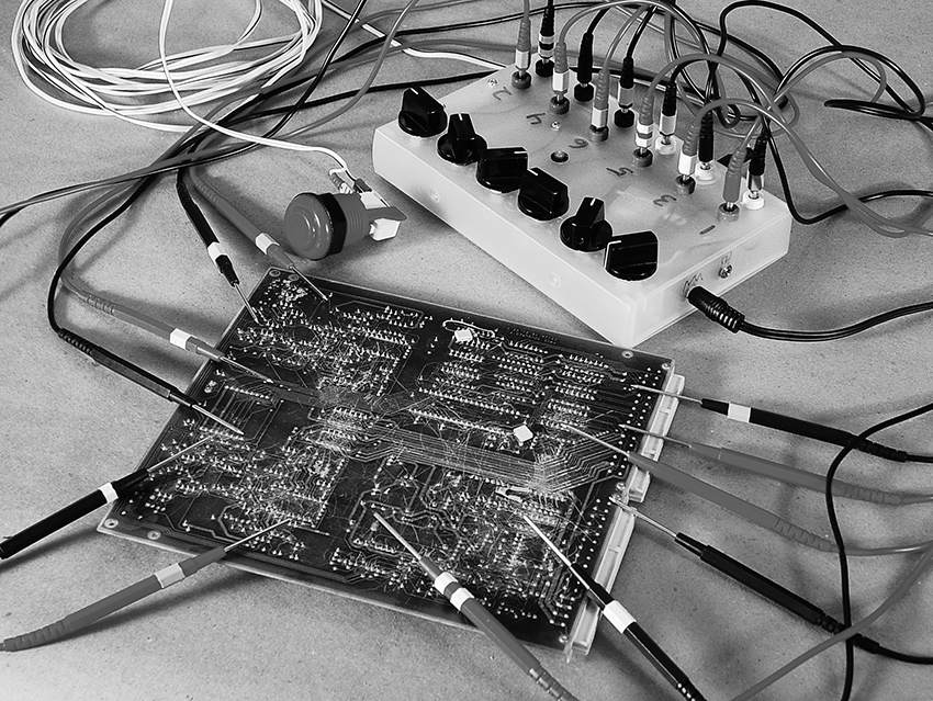
Figure 12 Nicolas Collins, Salvage—Guiyu Blues (2008). Control circuitry, probes and dead French Telecom circuit to be re-animated.
Sound and Vision
To state the obvious: sound is more than music. This has always been true, but the traditional distinction between “found” sound (produced in the world but living its life outside human intent) and “constructed” music (the imposition of human genius upon selected, designed sounds) is increasingly moot. Not only is music often “found,” sound is often “designed.” This is true in the rarified realms of art, the globalized realms of commerce, and the erudite realms of science.
Perhaps I’m attuned to this by virtue of having taught in an art school for the better part of a decade, but my ear tells me that museums, galleries and artists’ studios just keep getting noisier: it’s not that there is so much more Sound Art now than ten years ago, but rather that so much more art has sound. There are myriad reasons for this, from the high-falutin’ and theoretical to the incidental and pragmatic. For many artists the digital camera (often in a phone) has become the new sketchbook, and because it is so difficult to defeat the cameras’ built-in microphone, most video footage has sound by default. And, just as a camera often redirects the artist’s eye, so the constant presence of a soundtrack, whether intentional or not, draws attention to sound. My students shoot video for the sole purpose of gathering sound, and they play back the file without bothering to hook up a video monitor. When it comes time to edit, video and sound are cut and pasted using the same keystrokes and mouse clicks, with neither media privileged over the other.
As a result, music (or sound art, if you prefer) is emerging from art schools, utilizing many of the same materials and tools found in music schools, but often with a very different set of skills, aesthetic concerns and historical baggage. Some of this work takes the form of “pure sound”—digital files, vinyl, even cassette—but frequently it is characterized by a heightened sensitivity to visual implications of the technology of its production. That technology can be pretty diverse, since artists today tend to be “multi-instrumentalists”: the majority of my students don’t identify with a specific medium—they flit with ease between paper, film, videotape, wood, metal, computers, canvas and circuits.
As materials go, electronic toys with their lurid plastic casings, and homemade circuits packaged in cigar boxes and Pringles tubes, are more seductive to the eye than laptops and software. Moreover, for those who want to work with sound but lack traditional musical training, the learning curve is easier than that of most musical instruments.
Brett Balogh, Adrian Bredescu, Kyle Evans, Alex Inglizian, James Murray, and Aaron Zarzutzki—all former students of The School of the Art Institute of Chicago—are typical of this new generation. Balogh works extensively with radio technology, adapted as a creative medium, rather than a source of news or existing music (see chapter 27, in which he explains how to build a radio transmitter). Bradescu and Evans have built rich extensions of the circuits featured in this book. Inglizian is very active on the Chicago bending scene, conducting workshops as well as performing regularly, bending toys and building his own circuits (see figure 13 and chapter 21, his tutorial on advanced circuit bending). Murray draws on his background as a DJ to design homemade circuits, developing instruments for cutting and mixing, as well a multiple touch-radio synthesizers. Zarzutzki built a wonderful instrument from crystal oscillators intended for computer clocks: the crystals oscillate at frequencies in the megahertz range, well above human hearing, but the difference tones that result from non-linear diode mixing yields unstable tone clusters that we can hear (fig. 14).
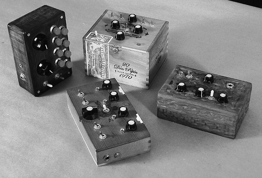
Figure 13 Various homemade circuits by Alex Inglizian.
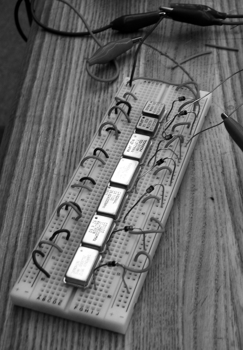
Figure 14 Aaron Zarzutzki: multi-crystal beat-frequency oscillator. Photo © Aaron Zarzutzki, used by permission.
This trend is not limited to trained artists, of course. A visit to YouTube makes it clear that video cameras (especially those built into phones) have supplanted not only the sketchbook, but the Brownie, Instamatic, Polaroid and Super-8 as well – the documentary tools of previous generations of amateurs. And the content on YouTube demonstrates the international popularity of bending and hacking as musical forms.
Some of the most interesting work to come out of the new audio-visual sensibility involves circuitry that either generates simultaneous audio and video signals, or allows the two to interact. Americans Jon Satrom (see his chapter 22 on video hacking) and J. D. Kramer (fig. 15) have independently hacked children’s video paint-boxes to generate fractured digital video and glitch-laden sound. The British trio of Phil Archer, Luke Abbott and Dan Thomas, as well as the American Jordan Bartee, use hacked Sega game consoles for live video and sound. Phillip Stearns’ (USA) Pixel Maelstrom is a video synthesizer constructed by radically bending an old TI99/4a microcomputer; Stearns has also created a series of pieces using an array of analog electronics to process sound and video through feedback loops.
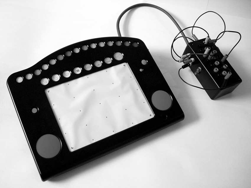
Figure 15 J. D. Kramer, Permutator video synthesizer. Photo © J. D. Kramer, used by permission.
In the spirit of Yasunao Tone’s Molecular Music (see sidebar “Visual Music” on website), Jeffrey Byron and Jay Trautman (USA), Joe Grimm (USA) and Infusion (USA) have built oscillators and signal processors that respond to film and light projection or sensors taped to a video screen. Michael Dudek (Germany) has connected oscillators and a bent keyboard to LCD TVs to disrupt the video sync and thereby modulate the broadcast images. Several artists—including BMBCon (Netherlands) and myself—have built simple video projectors using LCD screens from small TVs and handheld games.
At the more sophisticated end of the technological spectrum, the New York-based duo LoVid (Tali Hinkis and Kyle Lapidus) designed the Syncarmonica, a system of circuit modules, set into a table top, that can be patched together like an old-fashioned analog synthesizer to generate sound and video (see their chapter 22 on video hacking). LoVid has also embedded video and sound circuitry into soft sculpture such as their Ghoti (the title comes from the variant orthography for “fish” first suggested by William Ollier in 1855 as a comment on the irregularity of English spelling, though often misattributed to George Bernard Shaw). Ilias Anagnostopoulis (Greece) built an analog video synthesizer that harkens back to the Sandin Image Processor and Paik-Abe video synthesizer of the 1960-70s.
Mechanics
Alvin Lucier once said that circuitry didn’t interest him because if was “flat,” while sound in space was three-dimensional.2 Lucier’s student at the time, I bristled, but 33 years later I’m inclined to accept his analysis as a simple non-judgmental fact. Several contemporary artists have reacted to the flat, static nature of circuits and computers by incorporating mechanical devices in their hacks. In Leah Castleman’s (USA) installation Compose, Construct, Control, visitors press organ pedals with their feet to activate a beautifully crafted array of motors, cams, levers and cables animating an automated percussion ensemble composed largely of trash (fig.16). Martin Riches’ (UK/Germany) elegant “Motor Mouth” (1998-99) is an acoustic speech synthesizer, a mechanical version of the human mouth, with moving lips, teeth, tongue, tongue tip, larynx and a blower that serves as the lungs; its controlling computer is programmed with a few sentences and can also speak individual vowels, semi-vowels, nasals, labials and fricatives (fig. 17).
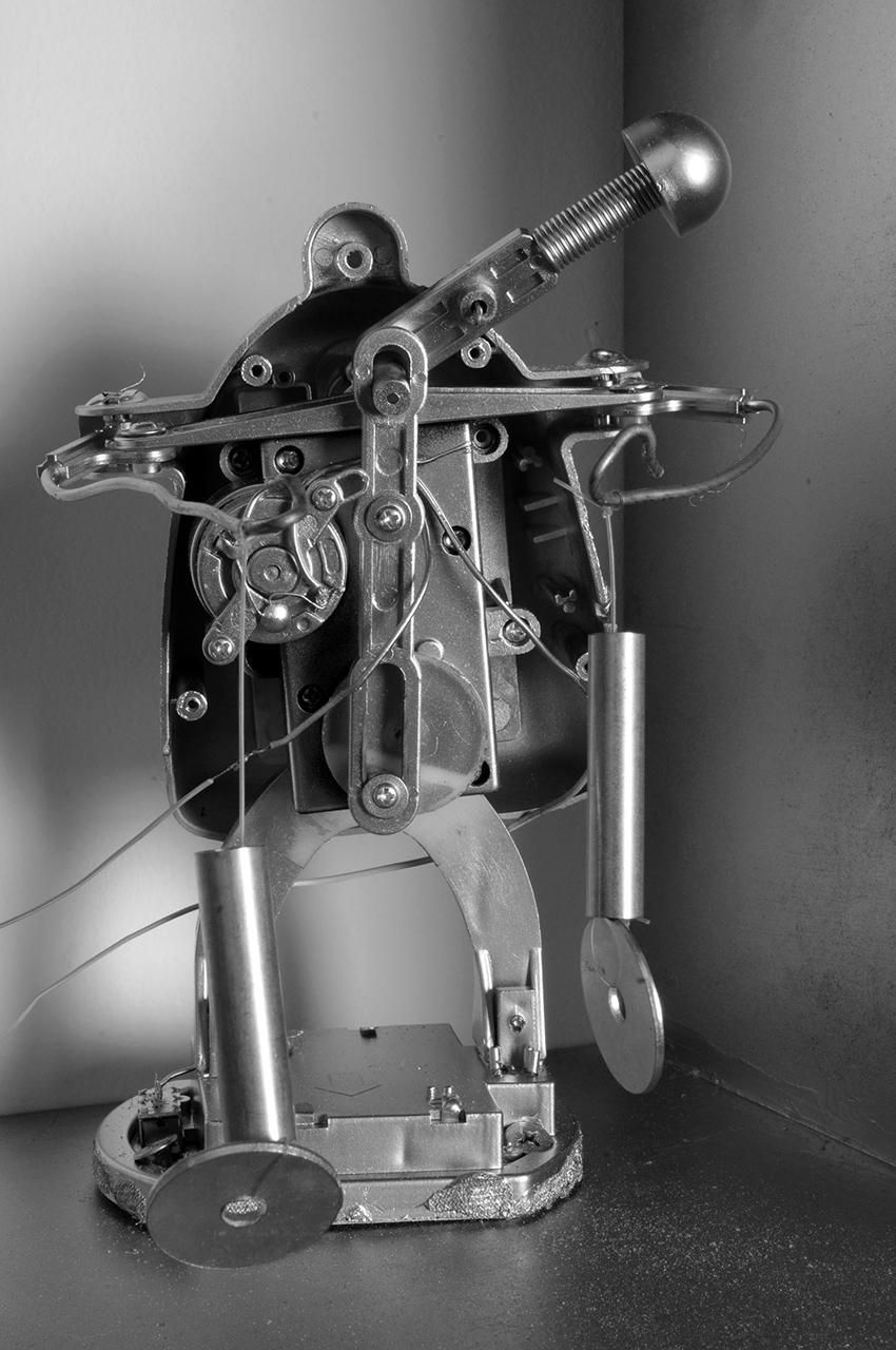
Figure 16 Leah Crews Castleman, Compose, Construct, Control, detail. Photo © Leah Crews Castleman, used by permission.
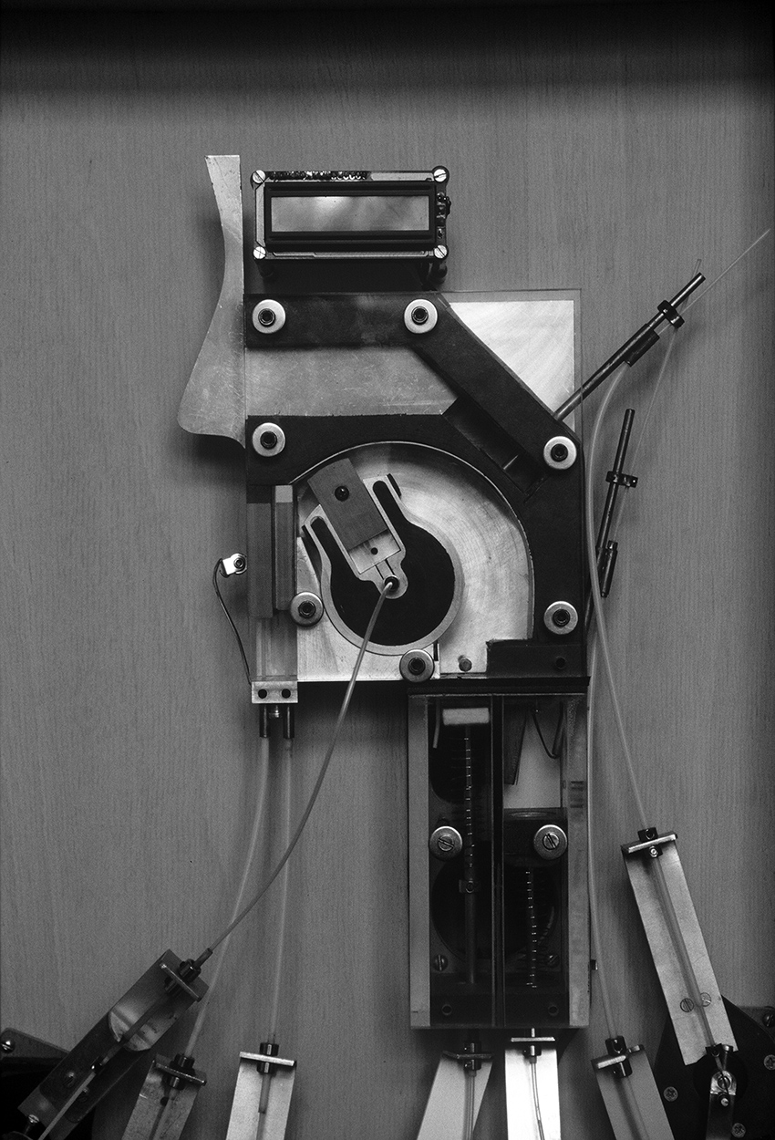
Figure 17 Martin Riches, Motor Mouth (1998-99). Photo © Martin Riches, used by permission.
A vaguely erotic physicality drives the work of Catalan musician Ferran Fages, who presses cones of styrofoam against the spinning platter of a cheap record player; the result sounds electronic but is produced purely acoustically, through friction, in a nod to the record player’s pre-electronic, gramophone roots. Similarly, Chris DeLaurenti’s (USA) Flap-o-phone is a manually activated, acoustic turntable: folded cardboard, a needle, and a stick exhumes sound from 78 rpm records; this is a variant of the CardTalk record player devised in the 1950s by Christian missionary Joy Ridderhof for playing back Bible recordings in unwired locations.
The historicism implicit in mechanical devices is knowingly exploited by Guillermo Galindo (Mexico), who describes his MAIZ as a “cybertotemic instrument”: an assemblage of trash (wine crate, street sweeper parts, credit card, cigar box) and instrument parts (guitar neck and three strings), all whacked by a powerful motor controlled by a computer in response to various sensors. The MAIZ merges pre-Colombian imagery, hurdy-gurdy mechanics and digital interactivity. Marc Berghaus (USA) chose gears over computers, and uses Newtonian technology to create “chance machines” for generating haikus, throws of dice, and permutational music on tiny acoustic pianos (fig.18).
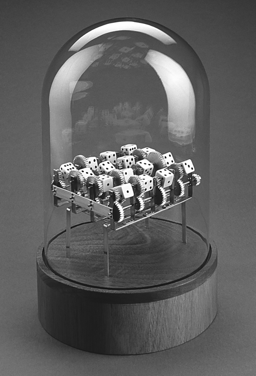
Figure 18 Marc Berghaus, Mandala #2 (2000), mechanized dice thrower. Photo © Marc Berghaus, used by permission.
Swashbucklers
Driven by the desire to hear a world just over the horizon, more and more artists are building circuits from scratch, either to aid and abet the transformation of found technology, or in its stead. Sebastian Tomczak and Christian Haines in Australia; Tuomo Tammenpää in Finland (fig.19); Alejandra Perez Nuñez in Chile; and Douglas Ferguson and Steve Marsh in the USA have all developed extensions of the sort of circuitry featured in this book. In addition to his beautiful spring-and-piezo gamelans, as shown in the Piezo Music sidebar in chapter 7 (figure S3.3), ADACHI Tomomi (Japan/Germany) has been building and selling quirky Tupperware-encased music circuits since 1994 (fig. 20). Florian Kaufmann (Switzerland) and Osamu Hoshuyama (Japan) are both serious fans of CMOS audio, and have set up web sites with designs that go well beyond those I discuss.
Figure 19 Tuomo Tammenpää, NANDsynth (2007), oscillator group. Photo © Tuomo Tammenpää, used by permission.
Figure 20 ADACHI Tomomi, assorted Tupperware-encased instruments. Photo © ADACHI Tomomi, used by permission.
Todd Bailey (USA) incorporated numerous contact points and an open area for extra components in his audio sampler kit, Where’s The Party At, to encourage customization by the user (fig. 21). Beavis Audio Research has produced a guitar effect kit for those who fear solder: preamps, distortion circuits, filters, tremolos, etc. can be plugged together on a breadboard that connect to jacks and pots on a sturdy metal base (fig. 22).
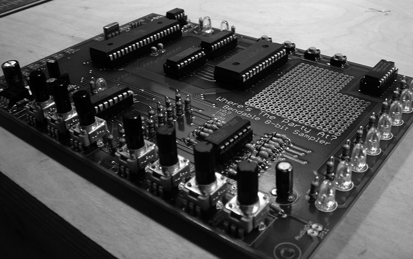
Figure 21 “Where’s The Party At?” Hacker-friendly audio sampler kit designed by Todd Bailey. Photo © Todd Bailey, used by permission.
Figure 22a “Beavis Board” (left) and parts kit (right), designed by Beavis Audio Research. Photo © Beavis Audio Research, used by permission.
Figure 22b
Hans w. koch (Germany) has created a series of pieces based on the physical idiosyncrasies of specific computers: in Bandoneon Book he opens and closes the lid of an Apple Powerbook with accordion like gestures to affect feedback between the computer’s built-in mikes and speakers; the feedback is further processed by software running on the computer, controlled from its keyboard. In Electroviola koch bows the case of another laptop; the sounds of rosin on plastic are picked up by the internal mikes and again transformed by his code. And in the melancholy tradition of Mahler’s Kindertotenlieder, koch’s Core-sound offers listeners the death rattle of an old PC as he drips water onto its motherboard.
In addition to the hand-generator-powered music boxes described earlier, Phil Archer uses the sled of a CD player to move the bottleneck on a tiny slide guitar (fig. 23). Gutting another pair of CD players, Archer connected the sled of each to the circuit board of the other, causing the lasers to chase each other’s tails and play back a torrent of glitches. Like koch, Archer has experimented with the heretical interaction of moisture and electricity, dripping water onto a Yamaha keyboard in his blithely-titled installation, What’s the Worst That Could Happen?. He has also incorporated growing plants in his circuits as components that react to human touch and presence in a distinctly spooky fashion, reminiscent of Tom Zahuranec’s experiments in the 1970s.3 Archer’s compatriot Dan Wilson has used a discarded dot matrix printer as the core for an instrument: he amplifies the printer’s internal springs, motors and coils, as well as some added strings, in his Printar (fig. 24).4 Wilson has built instruments out of floor sweepers, used the principles of the Victorian Oscillator (chapter 3) to pluck strings and springs, employed worms to play Cracklebox-style electrode-controlled circuits, resonated objects large (lampposts) and small (mbiras) with electromagnetic feedback (fig. 25) and, very briefly, persuaded a pair of hedgehogs to play a zither in his back garden.
Figure 23 Phil Archer, CD Player Slide Guitar. Photo © Phil Archer, used by permission.
Figure 24 Dan Wilson, “Printar”. Photo © Dan Wilson, used by permission.
Figure 25 Dan Wilson, thumb piano with electromagnetic drivers. Photo © Dan Wilson, used by permission.
Alex Baker (UK) created a number of pieces that explore the interaction of sound and mechanical forces. His Wind Powered Record Player (fig. 26) is an acoustic gramophone whose platter is turned by the wind. In Catch a ping pong ball is tossed into the air by a speaker cone pulsed with sound. Transducers attached to the heads of his Autonomous Drum Kit transform the skins into reversible microphone/speakers: first they are used to record sticks striking the drums; then they are reversed to play back the recorded sound through the heads, evoking a ghostly, phantom drummer.
Figure 26 Alex Baker, Wind Powered Record Player (2007). Wood, tissue paper, bearings, silver wire, record. Photo © Alex Barker, used by permission.
Douglas Repetto (USA) was instrumental is setting up dorkbot “for people doing strange things with electricity to get together to talk about their work” (see his history of dorkbot on the website) in New York City in 2000. Similar groups have since sprung up around the world. For years he was at the radical fringe of hacking culture as an educator at Columbia University’s Computer Music Center, an organizer, an inventor and an artist. In his Crash and Bloom, 42 identical small circuits emulate the cycle of growth and collapse of certain biological systems (fig. 27).5 For Fuseboxes Repetto built miniature noisemaking circuits into 20 tiny tin boxes from fuses. Slowscan Soundwave attempts to make sound waves visible by translating air pressure patterns in a room into the movement of suspended plastic sheets.
Figure 27 Douglas Repetto, Crash and Bloom (2001-2). Detail: three of forty-two circuits. Photo © Douglas Irving Repetto, used by permission.
Like Repetto, Phillip Stearns evokes the biological world in his impossibly complex AANN:Analog Artificial Neural Network (2007). Stearns soldered up 50 identical neuron-simulation circuits, interconnected them, and ended up with a “squid baby” that responds to sound and light by "lighting up like a Christmas Tree" and "shrieking like so many dying seagulls” (fig, 28) (see chapter 31 for information on building your own neural networks). For his Burlap series (2006) Stearns wove circuitry into fabric for exhibition on a gallery wall (fig. 29). Stearns’ video work, using both digital and analog technology, was described earlier in this chapter.
Figure 28 Phillip Stearns, AANN:Analog Artificial Neural Network (2007). Series of neuron subassemblies. Photo © Phillip Stearns, used by permission.
Figure 29 Phillip Stearns, Burlap-II (2006). Circuits sewn into fabric (detail). Photo © Phillip Stearns, used by permission.
Electronic components, as small as they are these days, are not quantum—they are things, and with a change of scale, the mysteries of what had previously been the lowest level of operation become tangible, touchable, hackable. Some artists experiment at this component level. Patrick McCarthy (USA) makes his own potentiometers with cardboard, safety pins and pencil lines. Nyle Steiner’s (USA) website, sparkbangbuzz.com, guides viewers through making their own diodes from zinc, using a flame as an amplifier, listening to a drop of salt water, building TV picture tubes and lasers from scratch, and other unusual projects. Substituting cozily familiar materials for the arcane can have a humanizing effect: Peter Blasser (USA) builds circuits on sheets of paper, rather than fiberglass circuit boards (see his chapter 26). Grégoire Lauvin (France) has created gallery installations that use live plants as capacitors in oscillators, causing the pitch world to change as the plants grow (fig. 30); he also built a Potatoes Organ whose notes are tuned by impaling vegetables and fruits on nails emerging from the instrument’s housing (fig. 31).
Figure 30 Grégoire Lauvin, Bio Oscillator. Plants and electronics. Photo © : Grégoire Lauvin, used by permission.
Figure 31 Grégoire Lauvin, Potatoes Organ. Vegetables and electronics. Photo © : Grégoire Lauvin, used by permission.
There is no conclusion
There is no conclusion, but there are anecdotes. Here is one: a few years ago I was conducting a hacking workshop at a very high-tech European music research institute. The group was made up of composers, computer programmers, acousticians and electronic engineers. One student got very confused as soon as we started breadboarding our first oscillator. I asked if he was by any chance either dyslexic or a conservatory-trained composer (two population groups for whom matrix topology seems unusually vexing). “No,” he replied cheerfully, “I’m an Electronic Engineer. I designed a complete Digital Signal Processor for my senior thesis, but I did it all with software on a computer -- I never actually touched a chip before today.”
My engineer is not alone. Sociologist Richard Sennet has observed that after computers became ubiquitous in the 1980s, “we tended to forget the importance of physical senses.” Or, as Bill Burnett, Executive Director of the Product Design program at Stanford University, put it: “a lot of people got lost in the world of computer simulation.” Burnett goes on to add the all-important truth that “you can’t simulate everything.” That simple and obvious idea—that there is a world before and beyond simulation—has become ever more important as the virtual has snaked its way into more and more of our waking hours.6
But the material world is making comeback. Make magazine, the de-facto journal of record for hackers of all stripes, boasts a paid circulation of 100,000 and 2.5 million visits per month to its web site. Bug Labs in New York sells Lego-like components that let the user snap together GPS receivers, cameras, LCD displays, motion detectors and other sub-modules to design and build their own digital products; the company “envisions a future where CE stands for Community Electronics [and] the term ‘mashup’ applies equally to hardware as it does to Web services.”7 A West Coast activist who goes by the name of Mr. Jalopy drafted a “Maker’s Bill of Rights,” insisting that “meaningful and specific parts lists shall be included . . . batteries shall be replaceable” and so on.8 “I want companies to start thinking about shared innovation,” says Jalopy, “to realize that they’re not selling to customers, but to collaborators.”9 The software giant Adobe invited Gever Tulley, who normally teaches children at his Tinkering School in Montar, CA, to get their designers to put down their mice, pick up their screwdrivers and make things. “The physical act of making things helps the whole person,” says Tulley.10
The first edition of Handmade Electronic Music was intended as an invitation to reach out and collaborate with commodities, and as an introduction to those pioneers who had been doing so since the dawn of the silicon age. All puns intended, it seems to have touched a chord, or at least to have bumped one string of an ongoing arpeggio. Today there’s more to listen to, more to look at, more to learn, more pages in this book.
There you have it: a plethora of circuits, suggestions, and glimpses of the work of some of the most interesting artists ever to confront a clip lead or soldering iron. The rest is up to you. Run outside and play.
1 When my son was around 11 I demonstrated to him a hack that I thought he might enjoy. He sighed, shook his head, and said, “Dad, in this world there are Makers and there are Breakers. You are a Breaker, Steve Jobs is a Maker.”
2 Alvin Lucier’s comment on the flatness of circuitry was made during the videotaping of Robert Ashley’s series of portraits of composer, “Music With Roots In The Aether” (Lovely Music, 1976).
3 Tom Zahuranec was one of the first artists to experiment with the musical application of plant response to human presence. He was active in the mid-1970s, primarily in the San Francisco Bay Area. He appeared in the Walon Green’s 1976 documentary film, “The Secret Life of Plants”, which is available on Google Video.
4 No mention of the musical use of printers would be complete without The User, a Canadian artists’ collective (Thomas McIntosh and Emmanuel Maddan) who send synchronized, specially-programmed print commands to dozens of obsolete printers in order to create their massive “Symphony for Dot Matrix Printers”. See: http://www.theuser.org/dotmatrix/en/intro.html
5 Douglas Irving Repetto. “Crash and Bloom: A Self-Defeating Regenerative System”. Leonardo Music Journal Volume 14 (2004). Pp. 88-94
6 Sennet and Burnett quoted in: G. Pascal Zachary. “Digital Designers Rediscover Their Hands”. New York Times. August 17, 2008. Sunday Business section, p. 4..
7 Bug Labs company website, 2008.
8Maker’s Bill of Rights (2006). https://makezine.com/2006/12/01/the-makers-bill-of-rights/
9 Quoted in: Lawrence Downes, “Mister Jalopy Wants to Make a Better World,” The New York Times, 25 Aug 2008: A20. https://www.nytimes.com/2008/08/25/opinion/25mon4.html
10 Quoted in Zachary, op. cit.